Università degli Studi di Palermo Dottorato di Ricerca in Ingegneria Informatica
DIPARTIMENTO DI INGEGNERIA INFORMATICA
Peer-To-Peer Architectures in Distributed Data Management Systems for Large Hadron Collider Experiments
Collaborations: 04/02/2005
CERN-THESIS-2005-075
Ph. D. Candidate GIUSEPPE LO PRESTI
Tutor Prof. SALVATORE GAGLIO
European Organization for Nuclear Research PH Department, CMS TriDAS Group
Consiglio Nazionale delle Ricerche
Ph. D. Coordinator Prof. ALESSANDRO GENCO
Istituto di Calcolo e Reti ad alte prestazioni
Tesi di Dottorato di Ricerca in Ingegneria Informatica - XVI Ciclo Palermo, Dicembre 2004
Cover background: part of the Compact Muon Solenoid detector being built at Cessy (France), for the CERN Large Hadron Collider experiments.
Abstract
The main goal of the presented research is to investigate Peer-to-Peer architectures and to leverage distributed services to support networked autonomous systems. The research work focuses on development and demonstration of technologies suitable for providing autonomy and flexibility in the context of distributed network management and distributed data acquisition. A network management system enables the network administrator to monitor a computer network and properly handle any failure that can arise within the network. An online data acquisition (DAQ) system for high-energy physics experiments has to collect, combine, filter, and store for later analysis a huge amount of data, describing subatomic particles collision events. Both domains have tight constraints which are discussed and tackled in this work. New emerging paradigms have been investigated to design novel middleware architectures for such distributed systems, particularly the Active Networks paradigm and the Peer-to-Peer paradigm. A network management framework has been designed and developed, which is able to carry on network management tasks and failures detection. Moreover an Artificial Intelligence based autonomous agent has been prototyped, in order to support the network administrator in pursuing his management responsibilities. The Active Networks paradigm has been used in this context to enable network programming. In addition, a software prototype has been developed to enable controlling of DAQ systems by means of distributed discovery services. A discovery service allows network entities to be acknowledged about each other, and enables them to expose and make use of custom services. The Peer-to-Peer paradigm has been leveraged to implement a discovery service to ease configuration and monitoring of distributed DAQ systems. The research and development activity carried on in both domains had the common goal of demonstrating how appropriate middleware can provide the required autonomy to systems under analysis.
v
Sommario
Lo scopo principale della ricerca presentata in questa dissertazione è lo studio di architetture Peer-to-Peer e l’impiego di servizi distribuiti per il supporto di sistemi di rete autonomi. Il lavoro di ricerca si è concentrato nello sviluppo e nella dimostrazione di tecnologie che consentissero l’autonomia e la flessibilità del sistema, nel contesto della gestione di rete e dell’acquisizione di dati distribuita. Un sistema per la gestione di rete consente all’amministratore di rete il monitoraggio di una rete di computer e la gestione corretta di qualunque guasto possa accadere durante la sua operatività. Un sistema di acquisizione dati (DAQ) per esperimenti di fisica delle alte energie raccoglie, combina e filtra una grande quantità di dati, i quali descrivono eventi di collisione di particelle subatomiche, e successivamente memorizza tali dati per ulteriori analisi. Entrambi questi domini possiedono vincoli particolarmente stringenti che sono discussi ed affrontati in questo lavoro. Sono stati investigati nuovi paradigmi emergenti per il progetto di moderne architetture di middleware per tali sistemi distribuiti: in particolare il paradigma delle Reti Attive (Active Networks) e il paradigma delle reti paritetiche (Peer-to-Peer). È stata progettata e sviluppata un’architettura per la gestione di rete e per l’esecuzione di compiti di amministrazione di rete e rilevazione di guasti. Quindi è stato sviluppato un prototipo di un agente autonomo, basato su tecniche di Intelligenza Artificiale, per supportare l’amministratore di rete nello svolgimento delle sue attività di gestione. In questo contesto è stato utilizzato il paradigma delle reti attive per sfruttare la possibilità della programmazione della rete. Inoltre, è stato sviluppato un prototipo per il controllo di sistemi DAQ tramite servizi di discovery distribuiti: un servizio di discovery consente ad entità di rete di scoprire reciprocamente le altre, nonché di condividere i propri servizi. In questo ambito è stato sfruttato il paradigma delle reti paritetiche per implementare un servizio di discovery che faciliti la configurazione ed il monitoraggio dei sistemi di acquisizione dati distribuiti. L’attività di ricerca e sviluppo condotta in entrambi i domini ha avuto lo scopo comune di dimostrare come l’uso di middleware opportuno possa fornire l’autonomia richiesta ai sistemi analizzati. vi
Acknowledgements
This work has been supported by the Italian Doctoral Students Programme, and specifically by the University of Palermo, Italy. Moreover, part of the work presented in this dissertation has been made possible thanks to the CERN Doctoral Students Programme, which provided the allowance to work at CERN Laboratories for Particle Physics in Geneva, Switzerland. I wish to thank my office mates and colleagues, both at University of Palermo (Mauro Barone, Piermarco Burrafato, Pierluigi Chirco, Vincenzo Conti, Luca Gatani, Giovanni Neglia, Marco Ortolani, Ignazio Selvaggio, and many others) and at CERN (they are too many to mention all of them!) for their friendship and help. Moreover, I have to thank Bernard Traversat, leader of the Jxta project, and the guys involved on it, for their concrete support during the development work. I am indebted to my tutor at the University of Palermo, Prof. Salvatore Gaglio, and to my supervisor at ICAR, Prof. Giuseppe Lo Re, for their precious aid. Furthermore, I’m obliged to my supervisor at CERN, Dr. Luciano Orsini, and to Dr. Johannes Gutleber, for their continuous support during the period spent at CERN. My warmest thanks go to my sister Rosa Maria, which always supported me not only in my work but in everything. Finally, my parents. I could not have come to this point without their constant encouragement from childhood. Thanks papà e mamma for all!
vii
viii
Contents
Abstract
v
Sommario
vi
Acknowledgements
vii
Contents
ix
Introduction. Distributed Data Management systems I.1. Brief excerpt on the carried research activity
1 2
Chapter 1. Infrastructures for distributed autonomous systems
5
1.1. The Active Network paradigm: pros and cons 1.1.1. A survey on Active Network Execution Environments
5 7
1.2. The Peer-to-Peer paradigm: features and challenges 1.2.1. State of the art in Peer-to-Peer systems
11 13
Chapter 2. ANgate: an architecture for distributed AN management 25 2.1. Overview
26
2.2. The AN Gateway Architecture 2.3. Practical implementation
29 31
2.3.1. The Gateway service
31
2.3.2. The Management Modules 2.3.3. The Active Local Agent
34 36
2.4. Case study: prototyping an intelligent management system for ANs 2.4.1. Architecture
39 40
2.4.2. Reactive Golog 2.4.3. The Ontology
42 43
2.4.4. Experimental tests 2.4.5. Performances and scalability issues
45 46
ix
Chapter 3. Data Acquisition Systems for High Energy Physics 3.1. Data Acquisition Systems at CERN 3.1.1. CERN and the LHC experiments 3.1.2. Overview of the CMS experiment 3.1.3. The on-line Trigger and Data Acquisition system for CMS 3.2. Distributed Data Acquisition: requirement analysis 3.2.1. Functional requirements 3.2.2. Non-functional requirements 3.3. XDAQ: a Peer-to-Peer framework for Data Acquisition
49 49 50 52 54 57 57 59 60
Chapter 4. Peer-to-Peer and Discovery for Distributed Data Acquisition
67
4.1. Autonomy and auto-discovery features of Peer-to-Peer systems 4.2. JXTA as a platform for DAQ
67 70
4.2.1. JXTA fundamentals 4.2.2. The JXTA protocols
70 74
4.2.3. An outline of the Java and C reference implementations
77
Chapter 5. Case study: a JXTA-based XDAQ Peer Transport
81
5.1. General description and architecture
81
5.2. Use cases 5.3. Implementation
83 85
5.3.1. The Rendezvous peers 5.4. Experimental tests
89 91
5.5. Performances and scalability issues
93
Conclusions and future directions
97
Appendix A. ANgate source code
101
A.1. The Gateway service A.2. The ALA service
101 105
A.3. The logical inference engine
114
Appendix B. JxtaPT for XDAQ source code B.1. The user’s API B.2. The Java Rendezvous
127 127 137
References
143
x
Introduction. Distributed Data Management systems
The need for managing distributed data stems from a spread field of disciplines that can generate large amounts of data. Applications producing such an amount of data are generally data intensive. In this context, the term distributed identifies a set of machines interconnected by a high performance network. A centralized approach could strongly affect the system performance; therefore a distributed approach is often beneficial. Examples are Large Hadron Collider Data Acquisition systems which are under development at CERN. Distributed data acquisition systems collect data from embedded devices and process them for later use. Such systems rely on an infrastructure that facilitates the data acquisition task. This underlying infrastructure deals with a number of upcoming issues in distributed computing: •
architectures for distributed applications
•
control and configuration of distributed applications
•
contents and code distribution
•
application intercommunication
•
fault tolerance
•
service discovery
•
scalability and communication performance
•
independence of physical technologies for communication
In the present work distributed architectures for networked environments are investigated, in order to take advantage of the services provided by such architectures to develop appropriate middleware. After a review of current state-of-the-art technologies for distributed systems, two outstanding paradigms are exploited in the present dissertation: the Active Network paradigm and the Peer-to-Peer paradigm. Software prototypes and performance tests are provided to fully evaluate each environment. Afterwards, a requirement analysis has been carried to address the issues shown above and software architecture has been devised, taking 1
advantage on existing Peer-to-Peer technologies. Finally, conclusions are drawn and future directions on ongoing work are discussed.
I.1. Brief excerpt on the carried research activity During the Ph. D. course a number of different research areas have been covered and a brief report of the most important achieved results is provided here. The research activity started with an analysis of current advancements of the Steiner Problem in networks, a typical network optimization problem which arises on designing networks for multicast applications, such as richmedia content delivery to multiple destinations, as well as other network design related scenarios. A study on scale-free network topologies such the Internet has been carried on, and novel meta-heuristic methods have been devised and developed to obtain better solutions to large problem instances, including a Simulated Annealing algorithm and a parallel Grid-enabled Genetic Algorithm. Main results have been published in [DLL01], [DLL03], [LLSU04], and [STE]. Afterwards, the Active Networks paradigm has been taken into consideration as a first distributed environment to deploy distributed management systems. A software prototype for an Active Network management framework has been designed, and an Artificial Intelligence based autonomous agent has been developed, which is able to carry on basic network management tasks by means of the management framework previously mentioned. Main results have been published in [DGLL02], [DGLLI03], [GGLLU04], and [ANG]. Finally, the Peer-to-Peer paradigm has been taken into account as a distributed environment to deploy distributed Data Acquisition systems, in the context of High-Energy Physics experiments. An online Data Acquisition (DAQ) system for high-energy physics experiments has to collect, combine and filter a huge amount of data describing subatomic particles collision events. In this context, existing technologies have been utilized to facilitate configuration and monitoring of such systems, and a software prototype has been developed, which enables DAQ systems to be monitored by means of Peer-to-Peer distributed discovery services. Preliminary results are going to be published in [GLO05] and [LoP05].
2
3
4
Chapter 1. Infrastructures for distributed autonomous systems
Information technology distributed systems are characterized by computer applications that consist of several components running on different computing systems, and autonomous systems are computer applications that are able to perform complex tasks without human intervention. In the recent years, Information Technologies have grown with an increasing rate, making such systems more powerful but also more complexes. The world-wide Internet, while providing seamless interconnection across distant locations enabling new paradigms, opens new challenges in the context of distributed and autonomous systems: a huge effort has been devoted by the research and the industry communities to conceptualize, design, and develop appropriate middleware infrastructures, capable of operating and controlling large systems. The present dissertation deals with middleware software for distributed networked autonomous systems. New emerging paradigms have been investigated to design novel middleware architectures for distributed systems. In this preliminary survey two outstanding paradigms are analyzed: the Active Network (AN) paradigm and the Peer-to-Peer (P2P) paradigm.
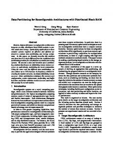
1.1. The Active Network paradigm: pros and cons Active Network is a novel approach to the network computing which has been proposed on late 90s to introduce programmability in the network, giving the possibility to execute customized computations on the messages flowing through the routers. Networks which enable the user to customize their behaviour are active in the sense that nodes can perform computations on and modify the packet contents [Ten97] (see fig. 1.1). The concept of Active Networking emerged from discussions within the DARPA research community in mid 90s, in order to address some issues of today’s networks: in particular, one of the initial goals was to test and de5
ploy new network protocols in a wide area network environment overcoming the limitation of traditional networks, where the standardization process is very long compared to the typical evolution of users’ needs. But this paradigm goes further and enables autonomy features: in fact, as active routers can run small computations, active packets can act as autonomous agents running distributed tasks. The major advantages against end-to-end network software and systems are a better inside view of the real status of the network, which enables distributed software to gather needed information and process it along the way, and on a theoretical basis a new computational paradigm beyond the classical Turing Machine.
Fig. 1.1 – Classic vs. Active Network paradigm (source: DARPA, 1998).
However, allowing users’ code to be run inside the network introduces new safety issues. Malicious code inside packets can easily attack routers, and node resources consumption must be monitored and limited by suitable mechanisms in order to avoid that a users’ code locks a router. Moreover, a number of security issues must be solved concerning authorization and credentials about what kind of code can be executed. In ANs two different models can be recognized: a discrete approach, which implies that active routers are programmed via an out-of-band mechanism, so they behave as programmable switches, and an integrated approach, where every packet can carry both data and code. The first one has been preferred when program loading must be carefully controlled, al6
lowing network administrators to monitor and eventually restrict access to the router. The second one follows a more extreme view of this paradigm and it demonstrated to be more flexible, though safety and security issues must be taken into account as mentioned before. Another major issue of Active Networking is the intrinsic slowness of active nodes with respect to conventional routers. As optic technology’s performance is growing faster than that of CPU technology, there will be less and less CPU time available to process each packet. Therefore, a trade-off between pure network performances and application complexity must be considered on designing a distributed active service. In the context of the world-wide research on Active Networking, some facilities have been devised by the research community to allow interoperation between prototype ANs and classical networks. First of all, an Active Network Encapsulation Protocol (ANEP) have been devised by University of Pennsilvania and others [ANEP], which allows seamlessly encapsulating any active packets in standard IP packets, so that they can be routed as normal data packets and processed or executed only by active routers. Secondly, two main prototype backbones have been setup as virtual testbeds world wide, with active nodes spread mainly in USA and in Europe: ABone, an Active Network backbone [ABONE], and ANON, an Active Network Overlay Network. These testbeds support the ANEP protocol and the UDP transport layer, and allow the deployment and test of ANs over a wide network environment. Currently, only ABone is still running and supported. In the following, a brief survey on current and past Active Network prototypes is presented, taking into account their features with reference to autonomy and provision of distributed services.
1.1.1. A survey on Active Network Execution Environments Among AN Execution Environment projects, the followings are described here: PLAN, the Packet Language for Active Networks [Hic98], ANTS, an Active Network Transport System [WGT98], ASP, an Active Signalling Protocol [BRFL02], and Tamanoir [GL00]. All these environments with the Tamanoir exception are available in the ABone network backbone. For each environment, a basic description and a classification based on the proposed models is given; then the typical services provided by the environment are shown and safety and security issues are discussed. Finally a performance assessment is provided and the most important advantages 7
and drawbacks shown by the environment are given. PLAN PLAN [Hic98] is an ML-based language for ANs which follows the capsule model. Active packets are in fact small pieces of code based on a subset of the Objective CAML language [CAML], with some added primitives to express remote evaluation. When traversing the network, PLAN packets may invoke services, which are resident on the nodes. Therefore an Active Application is typically made by a single PLAN packet, which can propagate itself on a certain number of nodes and invoke needed services. The main goal of the platform is to allow ease of test and deployment of new protocols in a proof of concept environment model. Therefore performances are not a concern in the PLAN design, and the active node simply runs as a daemon process under common Linux O.S. Nevertheless, the system has shown a throughput up to 40 Mbps with standard hardware setup and 100 Mbps Ethernet network, but during long time tests it has been demonstrated that the daemon process can consume more and more hardware resources without restoring them, thus leading to resource leakages or crashes after some days of operation. The PLAN environment addresses safety using a straightforward mechanism: each capsule is given a certain resource bound, which acts as a TTL for the packet. Each time the capsule needs to locally or remotely evaluate a piece of code, its resource bound is decremented by the underlying EE; when it reaches zero, an error capsule is sent back to the sender. As in this context a remote evaluation is equivalent to forward the capsule to one or more nodes, this mechanism ensures that each capsule can spend a finite amount of CPU time in a finite number of nodes. If a capsule needs a more complex computation, it can access local services, which are statically linked to the EE and are written with the full O-Caml language. However, no security mechanism is provided to restrict access to potentially unsafe services on the node. In conclusion, the PLAN environment provides a full testbed to try out new protocols and distributed services, but among its drawbacks it lacks a stronger security model and production level performances. ANTS ANTS [WGT98] is one of the first Java-based Execution Environments for ANs, which enables ease of development and deployment of network protocols. It is based on the capsule approach and its main goal is to allow dy8
namical online deployment of new protocols. Namely, ANTS capsules can carry Java code, which can be remotely executed by active nodes. In the proposed prototype, the active node is implemented by a Java application that emulates a router and network concepts such as the packet and the protocol are virtualized inside the environment; authors demonstrated the proposed approach implementing capsules for mobile hosts handling and multicast transmission. Node safety is achieved through the standard Java applications sand-boxing, and the EE provides a basic form of resources protection to limit the use of network resources by AAs; however, there is no security mechanism provided for validating the custom code. The shown performances are poor, as this prototype implementation is not optimized for best throughput. In conclusion, ANTS has been developed as a proof-of-concept environment for early research on Active Networking, and the mentioned lacks prevent it on being implemented as is in a production environment. ASP ASP [BRFL02] is another Java-based EE that provides services to AAs defined by a Protocol Programming Interface. It does not use the capsule model, but instead fetches AA code out of band from the flow of active packets, thus achieving a better control on when new custom code is injected in the network. Active packets contain only references to the code that has to be executed on the EE. The design of ASP has been modelled following the requirements for dynamic deployment of complex control-related functions, such as network signalling and management. Therefore ASP includes support for persistent Active Applications, fine grained network I/O, security, and resource protection. In particular, security is achieved by means of a custom Java class loader, which eventually provides requested bytecode from another location such as the previous hop, and can be enabled to support signed Java code, thus preventing untrusted or malicious code from being executed on the node; moreover, different AAs executing within the EE are effectively isolated, so that an Application cannot crash another one or even the EE. On the other side, trusted core AAs can be given special privileges to strongly interact with the EE. With reference to performances and real use cases, a number of Active Applications have been proposed on a variety of areas, including QoS support, reliable multicast, and management, thus proving the effectiveness of 9
the platform in control-related contexts. On the other side, a shown drawback is that ASP does not provide a mechanism to limit use of network resources. TAMANOIR Tamanoir [GL00] is a software environment dedicated to deploy active routers and services inside the network. It is based on a discrete approach as the deployment of active code is carried on by means of a service broker. Tamanoir Active Nodes (TAN) provide standard routing and support both TCP and UDP transports; the active services support relies on the ANEP protocol. The main goal of this platform has been to achieve high performances on normal data packets while preserving a full featured EE for active packets; authors claim that in real scenarios the fraction of active packets is often very small compared to data packets, as the formers implement controlling or managing functions. The Execution Environment is based upon a demultiplexer which is able to receive and redirect active packets towards the called service by means of a hash key contained in the packets. The environment allows plugging new services dynamically, and an Active Network Manager is provided to deploy active services. The chosen language for active services is once again Java, and the active router is implemented as a Java application on top of a common off-theshelf Linux O.S.; the core routing functionality is implemented by means of a fast netfilter kernel patch to catch and route all normal packets. This way, the overhead for normal IP routing is negligible allowing high-performance networking, while the virtual Java-based environment still provides a full computational environment for active packets. Authors demonstrated the effectiveness of the proposed approach with experiments on Gbit networks. In conclusion, Tamanoir’s major benefit is the shown performances, while among drawbacks no security mechanism is provided by the environment. Related technologies The research on Active Networking demonstrated that the proposed approach in computer networking can be effective in highly dynamic environments, where it can be foreseen a benefit from the flexibility introduced by active packets. But in the last ten years no “killer application” has been shown which takes advantage of this technology and overcomes other ad-hoc solutions, and after an initial enthusiasm the current research has been de10
voted to specific contexts, where it is possible to take advantage of such a paradigm as a supporting technology. Among current AN research areas, Active Grid management projects (see for instance [GGLY03]) have been proposed recently in the context of the ongoing worldwide Grid projects: the aim of Active Grid management is mainly to leverage the Active Network experience to explore suitable middleware for the management of computational Grid. Moreover, it should be mentioned that no leading EE implementation has been emerged as a de facto standard, thus any project that relies on AN technology must take into account implementation details which are strongly dependent on the underlying environment. Nevertheless, the programmability of the network node, whatever it will be, has demonstrated being increasingly important, and in the present work this feature is leveraged in the context of a distributed network management system, as will be shown later.
1.2. The Peer-to-Peer paradigm: features and challenges The term “Peer-to-Peer” (P2P) refers to a class of systems and applications that employ distributed resources to perform a critical task on a decentralized basis. With the pervasive deployment of computers, P2P is increasingly receiving attention in research as well as in enterprise environments. Typical P2P systems have a series of key characteristics: as they are based on a peer model rather than a client/server one, each network node (peer) is able to communicate and share information with the others and the whole system is partially or totally independent on central servers. Furthermore, no peer has a full view of the network, and the global behaviour results from the local peers’ interactions. P2P is mainly focused on sharing resources through direct interaction of the peers; shared resources can be files, documents, disk storage, CPUs, network bandwidth, and even human resources. Such a dynamic environment set a number of challenges to the underlying middleware; in particular, a directory and indexing service is critical on P2P systems more than on C/S and WWW scenarios, because peer’s connectivity can be very unstable and classical DNS and IP for addressing peers can fail in a P2P scenario. So a DNS-independent overlay addressing and directory system must be provided to allow peers to effectively share re11
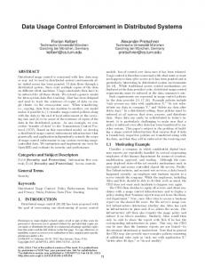
sources. On the other side, P2P systems potentially have more fault resilience and scalability features than C/S systems, and leveraging such qualities is one of the most important research areas in this field. A rough classification of P2P systems is presented in fig. 1.2, where the P2P “space” is divided into three main directions: distributed computing, file sharing and collaborative environments. General-purpose platforms, which enable the development and deployment of P2P systems, are shown in the center.
Fig. 1.2 – A classification of P2P systems (Source: HP, 2002).
In the following survey several distributed computing and resource sharing P2P systems are presented, focusing on their key features and drawbacks. Furthermore, for the aim of this work particular emphasis is given to resources’ discovery features of the system. For each of them a brief description of its goal is pointed out, together with a taxonomical classification; then an overview on the existing protocols, languages, and platforms on which it relies is given, and when appropriate an estimation of the configuration effort needed to run a sample application is provided. Afterwards, security concerns are briefly discussed and some hints about the commitment of enterprises and the developers’ community are given, as well as a rough classification of the maturity level reached by the system referring to
12
its standardization process. The most important advantages and drawbacks shown by the system complete the outline. Finally, some terminology is needed to identify particular aspect of P2P systems. First of all a servent [RFI02] is defined as a host that act both as a server and client, so it is a synonym of peer. Furthermore, a discovery service in the general case is a service which provides clients to locate resources, and resources to be published to clients. Such a service can be distributed among all peers, so that each peer (servent) is able to auto-discover other peers’ resources.
1.2.1. State of the art in Peer-to-Peer systems In this section, the following systems are covered: SETI@home and the BOINC platform in the distributed computing area, Napster, Gnutella, and FreeNet in the file sharing area, Avaki, JXTA, and .NET in the platform area. Furthermore, a number of related technologies are analyzed from a P2P perspective, including CORBA and Web Services middleware. SETI@home SETI (Search for Extraterrestrial Intelligence) is a collection of research projects aimed at discovering alien civilizations. Among them, Berkeley’s SETI@home analyzes radio emissions collected by the Arecibo telescope using the idle computing power of the subscribed users. It can be defined as a “reversed” C/S system for distributed computing: in fact, each “peer” receives a job and computes it during its idle time, as the peer software is a screen-saver program. A central database maintains all user accounts, and no discovery service is present, as it’s not needed indeed. As a CPU intensive oriented architecture, the system has low communication impact, because each job takes roughly a week of CPU time and few hundreds of Kb of transmitted data. The implemented protocol runs over TCP, and the client side is a software available on several platforms including Microsoft Windows, Linux, MacOS and Solaris, whereas the server side is a standard PHP web application with MySQL RDBMS running on top of a unix-like environment. The system is stable and well established because the project started in 1996, and it has inspired other “@home” scientific computing projects including medical tasks and weather forecasts. Now it is going to become an application built over the BOINC open platform [BOINC]; on this behalf a C++ API is made available to write a custom client both to run computation and 13
to show graphics using this platform, while it takes care of distributing jobs to clients. A typical trial application can be developed in few days. With reference to security concerns, the system is login-based, as each client needs to be registered in the central database. The main advantages are the scalability reached by the system (4,800,000 users so far), because the communication load is very low compared to the computing load, and good fault resilience: clients store their state every 1-2 minutes and the server is able to reassign a job after a timeout. On the other side, the architecture is specifically oriented to coarsegrain CPU-intensive computing, so it is not a general-purpose platform. Napster Despite it’s the most famous P2P application, Napster is a C/S system for file sharing, which uses a P2P model only during the final transmission of data. In fact, each peer needs to register itself to the central directory server before sharing its resources and querying the system, and no autodiscovery service is implemented in this system. Napster has proven to be scalable and effective despite the centralized server, because the server is queried only to get the references to the peers, and the number of messages needed to get a resource is always equal to 3; moreover as the shown results only span the online peers the probability of actually getting the file after a query hit is higher than competing file sharing systems. The implemented protocol uses HTTP GET requests for negotiating transfers, and TCP for transport. Security is centrally managed by a login mechanism. The main advantage of this system is a fast query response: an upper bound for the duration can be provided thanks to the simple network model [EPFL2002]. The counterpart is that the central server represents a single point of failure for the entire network, thus limiting fault resiliency. Gnutella Gnutella is a pure distributed P2P protocol for file sharing. It was born as an open source software, and its key feature is that it implements a distributed auto-discovery procedure: when a new peer wants to join the network it advertises itself to the others sending a PING message, and answers to the advertise sending back a PONG message. So the peers can dynamically create the network as long as they know at least one peer using out-ofband mechanisms. To start a query, a peer broadcasts it to all neighboring peers using the QUERY message, and if a peer has the requested resource it replies with a QUERYHIT message. As the query strategy is flooding based, 14
a query message has a limited TTL (usually less than 7), thus to limit its propagation over the network. In fact, the number of messages required to get a resource is O(dTTL) where d is the average node degree. The protocol runs over TCP and contains only five messages, the four previously mentioned and a PUSH message to enable firewalled peers to send file to not firewalled “clients” (if both peers are firewalled no communication is allowed). No authentication or security features are provided. So far several implementations of the peer software are known on the Internet, and the Gnutella network was studied in order to evaluate its performances. But the flooding model limits the scalability of the protocol and moreover it offers no guarantees on query results: no time bounds can be stated, and a query could even fail, i.e. it doesn’t discover the queried resource even if it’s present in the network. To address these issues, an evolution of this protocol has been presented which adds several enhancements. First of all, the pure P2P model is evolved to a 2-tier hierarchy model where most peers are connected to socalled ultra-peers, which act like hubs and directory servers. Ultra-peers create a pure P2P network. Secondly, each peer caches PONG messages, and routes queries following a Query Routing Protocol [GNUT] based on Distributed Hash Tables (DHT), so one or more keys must be assigned to each resource when it is put on the network. This way, the number of messages needed to get a resource in the average case is proven to be O(log n) thanks to the so-called small-world effect1 [GNUT], thus enhancing the scalability of the protocol. This model was adopted by several file sharing software (e.g. KaZaA, Morpheus, Joltid, eDonkey) and it’s worth to note that the QRP has been adopted and enhanced by other P2P indexing systems such as CAN, Chord, Pastry, etc. using techniques from the RDF (Resource Description Frame1
The small-world notion has been introduced in [Mil67] and is related to heavy-tailed
(fractal) distribution of some graph topology properties and the transition from regular graphs to random graphs. In a regular graph each vertex is connected to the nearest neighbors with high clustering, and the average path length is approximately n/2d, if n >> d >> 1, while in a random graph more bridges can be present and this value decreases to log n / log d, but the clustering is poorer because each node can be connected with any other, not only the neighbors. It has been proven that little changes in regular graphs are sufficient to achieve short global path length as in random graphs, maintaining the high clustering of regular ones: such graphs are called small-world graphs, and it has been shown that common computer networks show the properties of such graphs.
15
work, W3C) and Semantic Web research area to address the issue of finding a right key to index a resource2. FreeNet FreeNet is another pure distributed P2P protocol for file sharing, focused on anonymity and security: in fact, the protocol is structured in such a way that nobody knows where the resources are, and nobody can discover who asks for a resource. The query strategy is depth-first in order to avoid flooding of queries: each resource is ciphered and indexed by a key, obtained either hashing the content or a description provided by the user when the file is inserted in the system. Then each peer creates a routing table by getting the neighbouring indexes, and routes search requests only to the peer that own the closest key to the queried data. Moreover, the protocol supports a dynamic replica of most queried files to further shorten the average path length to the resource. The system is in a very early stage, as a first C++ prototype is freely available but no real world application is based on this protocol, nor companies are committed in developing it. Among advantages the scalability is similar to Gnutella with QRP, as the network exhibits small-world properties and in the average case the path length is O(logn), but local query routing decisions could be poor because of lack of routing information, so in the worst case the entire network still needs to be traversed, and a query could fail. Avaki Avaki is a commercial P2P and Grid platform for distributed computing; its main goal is to provide a single virtual computer view of a heterogeneous network of computing resources. It features an object-oriented layered architecture, where basic services are separated in three levels: core services including interface to the network and distributed directory and discovery, system services including accounting, load balancing and recovery, and application services including job scheduling and distributed file system. The platform is C++ based and the supported protocols are TCP/IP, .NET, Jxta; The QRP mechanism needs a set of keywords for each resource to be indexed. These words are manually chosen by the user in the music file sharing scenario, but if the resource contains more semantic information, a better technique can be devised to extract a 2
key which actually describes the resource’s content: this is the challenge which is tackled by RDF and Semantic Web research area.
16
custom protocols are not supported directly but as bridges to other platforms are provided a solution can be devised. As a Grid oriented platform it can run any binary code over the supported operating systems, which are Linux and Windows. Concerning security, it’s built-in as a core service: the authentication is login-based at startup, afterwards the middleware manages all further authentications required to run tasks over computing resources. The platform is still in an early stage; it is sell as a product and currently evaluated at various research labs, but a free working implementation is not available for testing. Among advantages, the layered architecture with a built-in directory service has to be mentioned, while among drawbacks it should be noted that Avaki is a commercial not-open-source platform, and the fault resilience support is present only at hardware level: if a node goes down, the middleware is able to migrate the job on another node, but in case of software fault nothing is done. JXTA Project Jxta (pronounced “juxta”3) is an open general-purpose platform for P2P applications. Jxta is structured in three levels of services: core, which includes security and peer group management; system, which includes searching and directory/indexing services; and application, where the P2P applications run using the underlying layers. Up to now several implementations are available: the most important are a Java implementation, which can be run on any Java enabled OS (either J2SE 1.3.x or J2ME), and a C implementation, though the latter is not as complete as the former. The protocols defined in the Jxta architecture are XML based. Moreover, Jxta is transport independent as it features a way to define custom “bridges” to even non-IP protocols like Bluetooth. With reference to security, a cryptography toolkit is available that enables message privacy and ensures authentication and integrity. The platform is in an early stage, but Sun and the Java community actively support it. Among third-party projects based on this platform, Edutella is an RDF-based metadata infrastructure for P2P applications. The setup of a Jxta network is straightforward and the number of tools
Jxta is the contraction of the word juxtaposing, i.e. side by side, which represents the P2P style in contrast to the classical C/S model. 3
17
built on top of Jxta is growing up. More on this platform will be presented later. The main advantages of Jxta are the distributed discovery service provided natively, the independency on transport protocols and the XML data and metadata representation. Among drawbacks, a scalability issue regarding global naming is still not resolved: Jxta doesn’t guarantee uniqueness of names in the peers’ network. A naming service shall be implemented to ensure a unique name on a given scope. Web services Among related technologies, web services are a standard to develop and integrate distributed application: in fact a web service can be defined as a «logical manifestation of some physical resources (like databases, programs, devices, or humans) that an organization exposes to the network»4. From a Peer-to-Peer perspective, a WS can be seen as a servent software component, because it’s a server when it receives a request from a client, and it’s a client as it can query other WSs, thus to establish a P2P network of even different services which can interoperate each other. But each WS needs to register itself to a central UDDI registry in order to be used by clients, and a client needs to know the registry address to ask for a WS using out-of-band mechanisms. So as far as all needed WSs are published on the same UDDI registry, a P2P-style application can run using all needed multiple instances of them. Protocols involved in WSs are UDDI and WSDL for resource discovery and description, and SOAP for RPC and data transport; all of them are XML based on top of HTTP. Several languages contain support for WSs, including Java and C++, and several different platforms are supported, because an XML parser and a web application container are the only key requirements to publish a software component as a web service. With reference to security, there is no built-in support, and each application must implement the required level of security. On the other side, lots of third-party tools allow the programmer to easy deploy a software component into a web service. For instance, a Java class can be published as a WS with minimal human intervention (the WSDL descriptor file is automatically generated). Web services are a standard maintained by W3C [WS] and actively
4
WebServices Journal, November 2003.
18
supported by all big names of IT. It’s worth noting that Grid computing is moving towards WSs, and for instance Globus Toolkit version 3 [GT] supports Grid Services, a WS extension for Grid applications. Among advantages, the interoperability and platform independency are the most important together with XML metadata representation, although transport of huge amounts of binary data is inefficient if SOAP has to be used. .NET Microsoft’s .NET is a commercial platform for distributed applications, which includes support for P2P-like systems. It is based on WS standards, as it includes UDDI, WSDL and SOAP protocols. The supported languages are C# and other .NET languages, and the reference operating system is the Windows Server family OSs. A minimal level of authentication is provided through the centralized Passport service, maintained by Microsoft. The platform has been proposed in 2001 and it’s in early stage development, supported by Microsoft and the .NET developers community. Among advantages the use of open standards like WS has to be mentioned, but the main drawback is that it’s currently available only on a single operating system. CORBA The Common Object Request Broker Architecture (CORBA) is the last middleware of this survey. It features a centralized directory service (broker), which takes care of handling requests and passing references to remote resources; so each software resource needs to be published, using the Interface Description Language (IDL), and no distributed discovery system is provided. CORBA supports a wide variety of languages, including C/C++, Java, Cobol, Smalltalk, etc. and relies on the IIOP protocol over TCP/IP to handle the RPCs. CORBA implementations are available on most platforms, from mainframes to standard PCs to handheld computers. The CORBA Security Service can provide a variety of security policies depending on the application’s needs. The configuration of a CORBA-compliant software is not straightforward because of the intrinsic complexity of the ORB (Object Request Broker): in fact, skeleton (server-side) and stub (client-side) software components have to be created for each resource that needs to be published in the CORBA environment. From a P2P perspective, if a software component is wrapped by both stub and skeleton parts and it is registered in the ORB, it can be seen as a CORBA P2P-style application as the middleware enables 19
peer-style connections to other instances of itself. Referring to the maturity level, the project started in 1997 and it is one of the first object-oriented evolutions of RPC; now it is standard and it is maintained by the OMG. Main advantages are the support for load balancing and fault tolerance policies, while the main drawback is the weakness of IDL, because it must be able to support a wide variety of languages. Rendez-vous Apple Rendez-vous [ARV] is a protocol that enables networked hardware components to connect each other with no human intervention, because it takes care of assigning proper TCP/IP configuration to each device. The discovery of a right network configuration is achieved through a broadcast based search: the device assigns itself an IP address in a valid localarea range and tries to communicate to other “peers”. If an address collision occurs, it changes the address and tries again until it’s able to connect properly with other resources. Moreover, the protocol leverages the Multicast DNS standard to allow discovery of services provided by peers. With reference to the maturity level, the protocol is in production state and is currently deployed by Apple, both embedded on networked devices such printers or wireless access points and integrated in the MacOS X Operating System. Furthermore, it is provided as an open-source software library. Finally, Apple Xgrid is a Grid technology built over the Rendez-vous protocol, which enables a group of even heterogeneous computers to run CPU-intensive coarse-grained parallel tasks. Xgrid basic principles are the same of the BOINC platform mentioned above. Among advantages, Rendez-vous is an open-source zero configuration protocol for network communication; its main drawback is the use of broadcast messages, which can result in poor scalability and reliability depending on the network environment. UPnP Universal Plug-and-Play [UPNP] is a network middleware technology, and allows automatic discovery and control of services available on the network from different devices without user intervention. The main focus of this technology is in home networking, with scenarios spanning from remote home devices control to their intercommunication; however, the standard defines a set of protocols for discovery and remote control of software services, and shares ideas from P2P context to enable such services. 20
The UPnP protocols are based on XML and they make use of SOAP over both HTTP/TCP and multicast UDP. As such, they can be run over several platforms and Operating Systems, including PDAs and embedded devices; the SDK includes a tiny web server to enable a UPnP device to communicate through HTTP. The UPnP has been standardized and a reference SDK implementation is available since 2002 as open source. It is actively maintained by all main IT vendors, including HP, Intel, and Microsoft. Main advantage of the platform is the low memory and hardware resource requirements, which allow running it over small devices. On the other side, the protocols essentially provide only the discovery service and basic control features, while other facilities from the P2P world, such as shared content management, are not included and must be developed or provided on a case by case basis. Related technologies Several computer networks technologies deal with discovery of resources and “peers” handling for different aims, from distributed storage systems to instant messaging systems, and often scalability issues are of major interest in such technologies. A brief summary of them from a P2P perspective is given here. Andrew File System (AFS) is a distributed file system, which allow to seamlessly merge on a single mounting point several Unix file system spread over the Internet. The key feature of AFS is its scalability; it has been achieved moving needed computation on the workstations (“peers”) that provide data, in order to not rely on a single server, and making best use of network connections through caching and batching transport of data. At a lower level, DHCP and wireless technologies (Bluetooth, 802.11) use a broadcast model to advertise and connect a device to other networked devices. DNS has a strictly hierarchical model for discovery: if a DNS server receives a query it cannot resolve, it always will forward it to its higher-level DNS server. Then the answer can be routed immediately to the first server or through each queried DNS server depending on the type of the DNS query. Finally, Instant Messaging systems use a centralized model for directory and discovery services, but some of them (for instance ICQ) are able to establish P2P direct connection between “peers” after the discovery phase has been finished. In the context of related technologies, Grid systems have to be mentioned once more, because of the great overlap with P2P systems; in fact, 21
thanks to the convergence towards Web Services, Grid Services can behave much like “peer” services sensu lato as they are able to perform computations on demand and can be connected each other in a peer-to-peer way. However, the typical requirements of Grid applications involve a robust architecture to effectively address safety and security issues, and this often leads to a trade off in performance and throughput capabilities, which usually are not of main concern in Grid scenarios compared to typical P2P scenarios. This trend must be taken into account in designing a distributed architecture for a real time task such as data acquisition. In conclusion, this section has shown the large variety of different approaches to the P2P paradigm, spanning from almost pure C/S systems to pure P2P systems; the architectures that have been revealed to be the most scalable and reliable are focused on a hybrid approach, in order to take advantage from both C/S and P2P paradigms. These architectures will be utilized later in the context of distributed data acquisition systems.
22
23
24
Chapter 2. ANgate: an architecture for distributed AN management
In this chapter an architecture for network and applications management is presented, which is based on the Active Networks paradigm and shows the advantages of network programmability. ANs can implement a complete distributed network management system, taking advantage of key features like: • availability of information held by intermediate nodes; • data processing capability along the path; • adoption of distributed strategies. The above features meet the network management requirements: mobile agents can be encapsulated and transported inside the active code of application capsules. They can retrieve and extract pieces of information held by intermediate nodes in a more effective way than through remote queries from the application itself. For instance, an agent could make use of an active code to look-up the Management Information Base (MIB) objects of an intermediate node and select some entries according to a given criterion. It can either send such extracted information back to the application, or it can use the information to take timely decisions autonomously from the application. Another example is a network topology discovery agent, which has been devised and is able to walk through the network and get back to the sender the full topology of the current active network. More examples can be found in other network management areas, such as congestion control, error management, or traffic monitoring. A more complete example is the customization of the routing function. A mobile agent could be devoted to the evaluation of the path for the application’s data flow, according to the user’s QoS specifications. Each application could set up its own control policy or make use of a common service. Finally, active networks applications can easily implement distributed strategies by spreading management mobile agents in the network. The introduction of network node programmability makes the network system one 25
single knowledge base, which is also capable of producing new information. This happens, for instance, when new actions are generated deductively from the resolution of previously stored data with occurrences of particular events, thus allowing the inference of new events and the triggering of codified measures. The architecture has been devised and implemented in the context of the present research work; the stimulus to develop such architecture arose from an actual need to manage a cluster of active nodes, where it is often required to redeploy network assets and modify nodes connectivity. The chosen name focuses on the central role provided by some special nodes in the network, which act as gateways to the active network environment, and allow decoupling management applications from the specific implementation details of the AN.
2.1. Overview In this section the overall Active Networks management framework is shown, focusing on the key functional characteristics of the proposed architecture. In particular, the programmability feature of ANs has been introduced in a MIB-like software component to make the management application itself distributed, cooperative, and adaptive ([ANG], [DGLL02]). The main goal of such architecture has to be the management and monitoring of active applications. Active applications management includes the deployment, integration, and coordination of the software components to monitor, test, poll, configure, analyze, evaluate, and control distributed network applications and the network resources being used. In this framework, shown in figure 2.1, the management application operates as a Managing Entity (ME) by means of a graphical user interface, and it sends queries and receives replays in XML format to and from an AN Access Point. An AN Access Point is an active node hosting a Gateway service. The tasks of a Gateway service are the translation of XML requests to the specific language adopted by the Execution Environments (EEs) and the injection in the network of the appropriate active capsules that perform ME requests. This way, the Gateway acts as an interface for a particular EE and it is specific for the language supported by that EE.
26
GUI XML wrapper
request [XML]
Management Application response [XML]
AN gateway
AN Access Point
EE = Execution Environment ALA = Active Local Agent
Active Network
XML parser EE Interface
EE
EE
ALA
ALA
active packets [ML, Java, …]
reports EE
EE
ALA
ALA
EE ALA
Fig. 2.1 – The ANgate overall architecture.
Several nodes in the active network can be configured to provide Gateway services. An overview of the Use Cases provided by the system from the AN Access Point perspective is given in fig. 2.2, where the main actors involved in the network management process are depicted. More details on the Gateway service will be given in the next section. The XML language has been adopted to define a set of requests/replies for basic operational tasks, which are common to any Active Network environment. For instance, the user can discover the network topology, explore the network nodes, find out those applications which subscribed the service and monitor their activities. In particular, we are interested to manage an AN testbed where novel management tasks are required as well, such as defining the active network topology to be deployed. For this aim the GUI provides a topology editor and the Gateway is able to manage the configuration and bootstrap phases of EEs in the active nodes, as it will be shown later. Furthermore, a resident management service called Active Local Agent (ALA) is installed in each active node. ME and ALA are the end points of the management communication. Namely, the ME can either query the Active Local Agents (polling) or deploy subtasks to them (programmable trapping). Subtasks are asynchronously performed by the local management agents, in 27
terms of actions to be executed at local events occurrences.
Fig. 2.2 – Main Use Cases Diagram for the ANgate system.
In the design of the architecture we moved from the traditional SNMP framework and introduced the advantages of programmability of the Active Networks paradigm. We redefined the role of the management agent and adopted a different model for the MIB (Management Information Base). In the traditional SNMP framework a managed device is a network equipment which, in general, may contain several monitorable objects, either hardware or software (for instance network interface cards or routing protocols). In this protocol the Managing Entity can request the local SNMP basic operations on the MIB, i.e.
SET
and
GET
the value of the objects. Differently from
the SNMP scheme, in our model the ME can program the local agents’ behaviour to accomplish independent tasks and consequently it becomes able to deploy a distributed strategy. A degree of programmability is also added to the MIB objects with the adoption of the object oriented programming paradigm. In our framework the managed objects are active applications, which are distributed applica-
28
tions whose software components run in both end nodes and intermediate nodes of the network. A managed application is an application which subscribes the management/monitoring service in a node by registering a unique ID to the local agent and which stores information into the Active MIB (AMIB). An AMIB object is related to a component of the managed application in the active node.
ALA - Active Local Agent NTP Active MIB
Active Capsule
Get/Set data, filters, and actions
Easync
Sync Events Generator
Esync
Clock and sync process
Agent Interface and Policy Enforcement
Actions Scheduler
Action Performer
Action result: - Active Capsule - Remote Report - Local/Remote set/get data, filters, and actions
Fig. 2.3 – The Active Local Agent Architecture.
The AMIB object allows storing the application data and a code fragment associated to the data. Namely, each object is not just a single variable storing a value, but it contains both data and code, where the code is represented as a set of conditions called filters. In ALA we implemented an Events-Actions model, as shown in figure 2.3. AMIB filters are (Test, Event) pairs, where the test is a boolean expression built over basic predicates by means of logical operators. Filter test verification means that the given event has occurred. The filter test is executed on the data when a primitive SetData call occurs, i.e. whenever the data may change. If the test succeeds the asynchronous event associated to the filter is raised and submitted to the Actions Scheduler.
2.2. The AN Gateway Architecture In this section the Gateway architecture is described, focusing on the control flow which allows the MEs to operate on the underlying network. 29
All Gateway services are offered over a TCP connection, by means of a protocol defined to interoperate between the MEs and the AN. The protocol supports commands for AN management in the form of XML wrapped requests and responses; the general format for a query is: ...
A similar format holds for the response: further information if pertinent
As all queries are implemented in an asynchronous fashion, the command name is carried back to allow demultiplexing on the receiving side. Moreover, the architecture supports multiple users, which can operate independently each other; therefore, as shown in the ANgate Class Diagram (fig. 2.4), each user is assigned a new instance of GatewayToClient and GatewayToNet classes, which are grouped by the main Gateway class. The first one is
an independent thread in charge of collecting XML requests and passes them to the second one, which in turn will create and inject a suitable active packet depending on the underlying EE.
Fig. 2.4 – The Overall ANgate Logical Class Diagram.
30
On the AN side, each implementation is requested to send back response messages by means of a standard TCP connection to the ANgate host; therefore all capsules must contain the information to allow proper demultiplexing towards the users. Namely, each active capsule includes the command name to which it refers to, the ANgate hostname and the TCP port number to which any reports have to be sent. The GatewayToPlan class listens for these messages, and eventually calls back the GatewayToClient class to forward the answer to the involved user, thus implementing the well-known listener - subscriber callback pattern. Finally, an authorization mechanism is in place in order to give different privileges to authenticated users. Specifically, only superusers can switch on and off the network, or inject custom active capsules, while normal users cannot interfere with other users’ activity. In conclusion, this architecture allows to transparently manage different kind of EEs and provides full multiuser support by means of multithreading.
2.3. Practical implementation To prove the effectiveness of the proposed approach, we implemented the Gateway service and the ALA on top of two of the main software packages for active networking, PLAN [Hic98] and ANTS [WGT98]. However, as shown the framework has been designed in order to be independent on the underlying Execution Environment, and new interfaces can be developed and plugged in without modifying the Gateway core implementation.
2.3.1. The Gateway service The Gateway service has been implemented by means of the Java programming language. It takes advantage of the Reflection APIs provided natively by the Java language to run different EE Interfaces on a homogeneous basis. An excerpt of the Java code that each EE interface must implement is shown in listing 2.1.
public interface IGatewayToANet { public void setANetPort(short port); public void setGatewayToClient(GatewayToClient gwToClient); public void closeANetPort();
31
public public public public
boolean startANet(Net aNet); boolean stopANet(); ANet isANetOn(); Vector getHosts();
public public public public public
boolean boolean boolean boolean boolean
suspendNode(String node); resumeNode(String node); actPing(String node); getNodeLinks(String node); runMonCapsules(String node);
public Iterator getCodesList(String codeType); public boolean injectRaw(String node, String capsule); public boolean injectToNode(String node, String capsule); public boolean injectToStar(String root, String capsule); public boolean injectToPath(String sNode, String dNode, String capsule); public boolean injectToANet(String root, String capsule); public String getALAVersion(String node); public boolean getALAAppList(String node); public boolean getALAVarList(String node, String app); public boolean getALAVarValue(String node, String app, String varName); public boolean clearALAValues(String node); public boolean setFilterAction(String node, String type, String app, String varName); // ... other specific services }
Listing 2.1 – Java code of the Gateway Interface to the EEs.
Here different group of services can be recognized: firstly, a set of core services must be provided to start and stop the Active Network daemons, and to retrieve the network topology (getHosts(), getNodeLinks()). Then a group of services is devoted to the injection of custom active code on the network: this is the key feature of Active Networking and it has been leveraged by means of Navigation Patterns. Namely, four different patterns have been identified for the deployment of active code on the network: • node simply deploys a custom capsule on a single node; • star deploys it on a node and its neighbours; • path deploys it on each node belonging to the shortest path between two given edge nodes; • net deploys it on the full network along the shortest paths’ tree, and provides the possibility to run custom active code both during the branching phase, when the capsule is broadcasted on the subsequent branches, and during the merge phase, on the way back to the root. 32
This way, the network administrator is able to deliver custom active code on the network and thus implement distributed strategies and protocols. Finally, the last group of service is related to the interaction with the ALAs: services include querying the AMIB by application name and variable name, and setting custom filters and actions related to them.
Fig. 2.5 – Gateway implementation Class Diagram.
A detailed view of the Gateway implementation is shown in fig. 2.5,
33
where the full Class Diagram of the mentioned classes is presented. Among others, the IGatewayToNet interface and one implementation, the GatewayToPlan class, are shown. As mentioned before, both GatewayToClient and GatewayToPlan instances are run concurrently, so the classes inherit from
the Thread class.
2.3.2. The Management Modules Referring to the user interface, the GUI management modules have been implemented as standard Java applets in order to be used remotely; they maintain a TCP connection to a ANgate host and communicate over this channel on a user driven basis. A few screenshots of the running system are shown in fig. 2.6, where a sample active network is running and some variables are monitored.
Fig. 2.6 – ANgate GUI screenshots. From left to right: the AN designer and manager module, the AA monitor module and the main window where the network manager can select the management modules to be used.
The main window on the right allows the user to select the Gateway server and the EE to interact with, and contains the buttons to the management modules. To this end, four management applications have been developed in the context of this project: the AN Manager, the AA Monitor, the MIB Browser and the Traffic Generator. 34
The AN Designer & Manager provides the basic management and system tasks, including switching on and off the EE daemons, discovering an existing active network, and send custom active capsules to the network nodes to deploy tasks to them. The Active Applications Monitor provides a GUI to the AMIBs available on the network, and allows to query for current variables and set custom traps according to the event-action paradigm shown before. The MIB Browser acts as a bridge with the standard SNMPcompliant MIB data, and allows to query for MIB values locally as well as on other SNMP enabled devices. Finally, the Traffic Generator is able to simulate traffic load scenarios on the network and allows studying the behavior and the performances of the active routers during overloaded conditions.
Fig. 2.7 – Login and service initializing scenario Sequence Diagram. 35
Although the lasts two applications concern other specific tasks, which are not related to the present work, nevertheless all the applications rely on the services provided by the Gateway servers as described above, thus proving the effectiveness of the proposed approach. A working scenario of all the mentioned components is provided in figures 2.7 and 2.8, where two Sequence Diagrams describe the login and the code injection use cases; the first shows the interactions from the user to the network interface, including the GUI on the client side and the Gateway classes Gateway, GatewayToClient, and GatewayToPlan; the second depicts the process in a more condensed fashion, and the asynchronous behaviour of the network in sending the answers is emphasized by means of the half arrows.
Fig. 2.8 – Active capsule injection Sequence Diagram.
2.3.3. The Active Local Agent The Active Local Agent has been prototyped for the Plan EE in the 36
form of ML services [CAML]. The choice of a ML language has been driven by the Plan implementation, which is based on ML, and it has the advantage of a functional approach which in most cases makes the implementation shorter than a traditional imperative language, though it’s more complex to understand; on the other side, a non-native code approach has shown to significantly affect the performances: this is not an issue for a prototype implementation, but it must be taken into account on a production environment. In order to provide a sample of the ALA services implementation, the publish and the getVarValue services are shown in listing 2.2 below: even
without dealing with details of the OCAML syntax, the listing shows that an hash table data structure, which is natively provided by the language, is extensively used to store AMIB objects and query them as if they belongs to SQL enabled databases. let publish (name, newv, app) = ( try ( let entry = Hashtbl.find pubTable (name, app) in match entry with (ts, v, t, filter) -> ( let t1 = grabType newv in Hashtbl.replace pubTable (name, app) (Unix.gettimeofday(), newv, t1, filter) ; newv ) ) with Not_found -> ( let t = grabType newv in Hashtbl.replace pubTable (name, app) (Unix.gettimeofday(),newv,t,[]) ; newv ) ) let getVarValue (name, app) = ( try ( let entry = Hashtbl.find pubTable (name, app) in match entry with (ts, newv, t, f) -> ( newv ) ) with Not_found -> ( Log.log_msg ("\nALA.getVarValue: variable not found or expired\n"); VList([]) (* returns an empty list as a void result *) ) )
Listing 2.2 – The publish and the getValue ALA services implementation. 37
Furthermore, listing 2.3 provides the related PLAN packet used to go and query for a value into an active node. Here the second-order function OnRemote is used to remotely evaluate a function, which is carried to the
target node achieving the code mobility mentioned before; the PLAN syntax |f|() means that the function f must be evaluated remotely but its ar-
guments have to be evaluated locally.
fun report(v, lport, anode, aaname, avar) = ( try let val p = openPort(lport) in ( printPort (p,"getALAVarValue: " ^ toString(anode) ^ " " ^ toString(aaname) ^ " " ^ toString(avar) ^ " = " ^ toString(v)); printPort (p,"\004"); closePort(p) ) end handle OpenFailed => ( print("No server listening on host "); print(canonThisHost()); print(" on port "); print(lport) ) ) fun varValueSend(gw, gwport, dst, aaName, varName) = OnRemote (|report| (getVarValue(aaName, varName), gwport, dst, aaName, varName), gw, getRB (), defaultRoute) fun doit(gwport, destination, aaName, varName) = ( let val gateway = canonThisHost() in try OnRemote (|varValueSend| (gateway, gwport, destination, aaName, varName), getHostByName(destination), getRB(), defaultRoute) handle NoRouteEntry => ( let val p = openPort(gwport) in ( printPort(p, "getALAVarValue: " ^ destination ^ " " ^ aaName ^ " unreachable"); printPort (p,"\004"); closePort(p) ) end ) end )
Listing 2.3 – The getALAVarValue PLAN packet which is sent to get an AMIB object.
The starting point of the packet is the doit() function, which is in-
38
voked by the Gateway when it injects the capsule on the first node; it calls the varValueSend() function, which has to be evaluated on the target node, thus asking the node to route the packet towards the requested destination. As the varValueSend() function is executed remotely, the packet asks once again a remote evaluation of the report() function, this time back to the starting point; this way the active packet performs a remote task and returns back to provide a report on it. The exposed pattern has been used for several report-oriented capsules, which implement all the required active services, and it shows how the network functionality is seamlessly integrated into the execution of the capsule. Finally, the experimental laboratory on which the system has been deployed and tested is constituted by a fully connected network of 40 active nodes, which allows running custom specific topologies. Each node is implemented by a Linux workstation equipped with four 100 Mbps Ethernet network cards to emulate a four ports active router. The active nodes are equipped with the Execution Environments mentioned above, together with all the implemented software components to run the ALA service on each active node, while the Gateway service has been run on a single node. This setup allowed to run typical network management scenarios, as the size of the network can be chosen in the order of tens of nodes, which is the same order of magnitude of common intra-Autonomous System networks. Among these scenarios, the case study proposed in the following section takes advantage of the main management applications, which allow controlling the Active Network and the ALAs.
2.4. Case study: prototyping an intelligent management system for ANs In the following, a proof-of-concept application is described, which takes advantage of the architecture shown above. The goal of the proposed application is to run basic management tasks in an intelligent and autonomous way, by adopting a two levels framework where a decision system behaves as Managing Entity, and the Active Network management system executes the operational tasks [DGLLI03]. The upper level automation is made possible by the adoption of a logicprogramming environment, which intrinsically owns special features that easily allow the achievement of tasks such as the decision of actions, the 39
prediction and classification of events, the diagnosis or explanation of failures, etc. Intelligent network management requires a model of the network, which is able to capture both the cause-effect relationships and their dynamic nature (time varying relationships). A logical inference process can use the system model to relate events that happen in the time-space to some other events which can be seen as their root causes. The situation calculus [Rei01] has been adopted to model the network and its dynamic evolution. The situation calculus is a logic language specifically designed for representing dynamically changing world. The designed management system can be classified as an expert system that adopts a case-based strategy [CMR89]. It is an expert system since it owns a complete knowledge of the working environment. Namely, among the logic predicates it is necessary to provide ontological descriptions for all the entities which populate the external world, and for all their relationships. Moreover, we provided the system with the further capability of retrieving new knowledge on the basis of the current situation where the world lies: if the information available in the knowledge base is not sufficient to reach some deductive goals, new data are required and successively acquired by means of specific sensors positioned in opportune nodes of the network. The twofold nature of the system allowed us to achieve a simple and accurate monitoring of the managed network. In particular, the capabilities offered by the Reactive Golog [Rei01] language have been used as the specific reasoning environment adopted to implement the system. The adoption of Reactive Golog language is due to its noticeable expressiveness and to its capability of providing simple and linear frameworks to the programmers.
2.4.1. Architecture In this section we describe the testbed architecture which has been adopted to implement the system. The general framework is shown in fig. 2.9 (next page). The central role is performed by the Online Logical Reasoner, which acts as a Managing Entity and is able to receive real-time data about the state of the network through the ANgate Gateway, and to infer actions and diagnoses. An RDBMS is connected to this logical Reasoner to store summarized data about past diagnoses; this way, the logical Reasoner is able to perform data mining across all logged data available on the network, since the SQL database will contain only the meaningful information that is 40
gathered from network nodes and filtered by the reasoning processes. Furthermore, if the user submits a query about a specific fault happened in the past, the Offline Reasoner is set up to answer the query, based on the data provided by the user. The Offline Reasoner could even load specific modules on demand, based on the submitted query, and it is able to store the results of the inference process in the SQL database as well, thus to enlarge the statistical data about detected faults. GUI user
Online Logical Reasoner
ANgate real time data
user data and modules Active Network
past data
Offline on-demand Logical Reasoner
Fig. 2.9 – The Intelligent Management System architecture.
The network environment on which the Reasoner performs its tasks is the Active Network management framework described in the previous sections. This implementation leverages both the ALAs, which are able to monitor and manage each node of the network, and the active capsules, which perform the actions planned by the logical Reasoner across the entire network. Each ALA contains a set of sensors which can be switched on to monitor a specific behaviour of the node; to this end, sensors for capturing early discard of packets, detecting routing table changes, and detecting neighbours state were developed; new external sensors (i.e. off-the-shelf software components which are able to detect some particular network variables) can be plugged as well in the ALA architecture, as they become available. 41
The local agents are modelled inside the logical engine as teleo-reactive agents [Nil98]. From the logical point of view, a teleo-reactive agent holds a set of simple rules and performs actions whenever the rule conditions are met. Hence the ALA filter-event-action behaviour can be regarded as a teleo-reactive agent implementation, where its variables constitute the discriminating values over which filters are installed in order to generate events, which in turn cause the execution of opportune actions. A key feature of this architecture is that the inference engine is completely decoupled from the sensors and agents implementation, making it easy to deploy the Reasoner in other network environments. Namely, the flexibility offered by the ANgate management framework allows the logical Reasoner to interact with other environments, provided that an interface is implemented inside the framework to gather data and send commands to that environment.
2.4.2. Reactive Golog To implement the system the Reactive Golog language as the specific reasoning environment has been adopted, which is based on common Prolog languages. The formalization of the world in this language is performed by means of well formed formulas of the first order logic, while the dynamism is captured by the primitive concepts of state, primitive action and fluent. The state is a snapshot of the world at a specific moment. All changes to the world can be seen as the result of some primitive actions. Relations whose truth values may vary in different situations are called relational fluents. They are represented by means of predicate symbols which take a situation term as their last argument. Furthermore, special logical rules must be provided to represent the time evolution. Primitive actions preconditions are rules that describe whether actions can be carried out given a state of the world. Preconditions are stated by fluents. The successor state axioms provide a complete description about the fluents evolution in response to primitive actions. They are needed for each predicate that may change its truth value over the time. Finally, procedures represent the complex actions and constitute one of the most important features of the Reactive Golog. They allow to group sequences of primitive actions and to implement recursive formulas using formal parameters. Generally, dynamic systems are not totally isolated from the rest of the world, but they continuously receive solicitations and interact 42
with the external world. The Reactive Golog rules allow these interactions describing how the world evolves when an external action is performed. This is the so-called reactive behaviour, as the model captures in a logic way any external “reaction” performed by the world.
2.4.3. The Ontology One of the key challenges of this work is the construction of a logic model capable of fitting as more as possible networking concepts. To this end, all the entities which constitute the network layer of the OSI reference model have been formalized. The ontological engineering process regards which network aspects should be represented and which form of representation could provide the most appropriate features. This induced to establish a relationship between the functional layers of the OSI networking model and some correspondent layers of dynamic knowledge representation. In this vision, the lower level view concerns the physical features of the network, while, for instance, routing devices and their connecting communication links represent knowledge at a higher level. Furthermore, this first amount of knowledge representation has been integrated with the capability of representing the functioning during the time. Logical sentences, whose validity is bounded to the time, have been introduced for representing the temporal status of a given node or a particular link. In order to represent the network environment as a dynamic system capable of flowing from a situation (current state) to another one (successor state), the network has been viewed as an active entity capable of carrying out actions which modify its own configuration. As a consequence, the knowledge base that has been developed is composed by two parts: the first is a static database which contains all the predicates which are independent from the time; this includes the formal description of the network topology and its components (nodes, interfaces, and links). The second part contains relationships and predicates which are time dependent, such as a node status, or a node routing table. To give a general representation of all predicates that belong to the designed ontology, the frame paradigm has been used. Frames [Min75] have been introduced in Artificial Intelligence to represent hierarchically structured knowledge bases. Each frame is a collection of attributes and related values which describes an entity of a given context. The main key feature is the inheritance, 43
which allows to define more and more detailed entities, as in the well known OOP paradigm (which in fact is a development of the frames paradigm). Figure 2.10 shows the frame representation of the knowledge base. All entities inherit from the general entity Thing, which only contains the slot name, used to identify each frame. Thing -Name
NetEntity -ISA : = Thing #Name -Status : = (ON, OFF, ABN)
*
Node -ISA : = NetEntity #Name #Status -Type -RoutingTable -IFaceList -NeighborList
Sensor -ISA : = NetEntity #Name #Status -Type : = (TTL, RT, AN, DN)
Actor -ISA : = Thing #Name
*
IFace -ISA : = NetEntity #Name #Status -Address
Link -ISA : = NetEntity #Name #Status -Type -Bandwidth -IFaceList
*
*
Ala -ISA : = Actor #Name -Node -SensorList
Reasoner -ISA : = Actor #Name Action -ISA : = Thing* #Name -Actor -Parameters
Capsule -ISA : = Actor #Name
Each Action instance has a variable number of parameters and its name has the form actorName_actionName
Fault -ISA : = Thing #Name -Type : = (LostPkt, RT, DN)
*
*
Cause -ISA : = Thing #Name -Type : = (Loop, RT)
Fig. 2.10 – The Frame representation of the Knowledge Base.
44
The first inheritance level includes the frame Fault (in yellow) which describes the faults that can happen in the network, and Cause (in yellow) to describe any fault’s cause. Action models the actions executed either by the network or by the Reasoner itself and the Actor (in green) frame describes all the modelled agents (Network, Capsule, Reasoner, ALA). Finally NetEntity (in light red) is the root frame for all the network related entities, including Node, Sensor, Iface, and Link. These entities represent the actual model of the OSI network layer, as stated before. The IS-A attribute held by all frames represents the mentioned inheritance relationship.
2.4.4. Experimental tests In order to test and evaluate the presented logical inference system the experimental setup described previously has been used, which includes the ANgate management framework to interact with the network. A series of experimental tests has been devoted to determine the reliability degree of the system, in terms of discovered faults and performed repair actions. For details about typical faults detection scenarios we refer to [DGLLI03]. Fault events have been generated according to a Poisson distribution for their temporal occurrences, and a uniform distribution for their spatial positioning. The network size has been selected in the range of 20 to 30 nodes, which as mentioned before is the typical size for intraAutonomous Systems such as ISP networks. The failures generated are listed in table 2.1, together with the results of the experiments. Fault
% Failure discovered
Errors in the RIP routing tables Early Packet Discarding Full Link Failure Full Node Failure Loops in the RIP routing tables Changes in the state of neighbor routers Backup Link Recovery
96 100 100 88 96 100 100
Avg. discovery time 10 s 5s 30 s 30 s 10 s 20 s 35 s
Table 2.1 – Summary of detected failures.
For each managed type of failure we report the percentage of cases discovered and the average time elapsed before the failure recognition. Most of the events are captured the full percentage of the cases. In the 45
cases of events directly discovered by the Active Local Agents on the nodes, for instance the case of changes in the states of neighbour routers, the discovering times are constant since they depend on the sampling time of the monitoring activity. The low percentage for the case of full node failure has to be related to the simultaneous failures of several nodes. In fact, the occurrence of such events may provoke a disconnection in the network, thus denying the capability of retrieving the necessary alarms. Last row shows the measures of the action adopted to recover a link failure. The average time of 35 seconds is the overall time since the full link failure, thus meaning that the recovery time is limited to 5 seconds.
2.4.5. Performances and scalability issues In this section some final considerations are argued for the proposed system. Referring to the structure, the novelty of the proposed architecture arises from the original idea of complementing a logical Reasoner with the versatility of Active Networks. The integrated system collects the advantages coming from logical reasoning and network programmability, and realizes a powerful system capable of performing high-level management tasks and dealing with unusual network situations. The logical Reasoner is, namely, able to deduce knowledge and find correlations from data and events which are distributed on different places of the network and which occurred in different instants; moreover, thanks to the AI approach it is possible to extend the capabilities of the Reasoner by means of high-level logical statements. Finally, the shown performances demonstrate the effectiveness of the proposed approach, as the system has been able to deal with typical faults scenarios that could happen in intra-AS sized networks. However, if we want to extend the system from a proof of concept stage to a fully working system, some scalability issues must be taken into account, which arose during the test phase: in fact, logical inference is a computational intensive task which is known to scale poorly with the size of the problem, which in this system is represented by the number of edges in the network. Namely, the computational complexity and the memory requirement for a generic inference process are O(2k), where k is some typical dimension of the investigated domain. In this context, the number of involved predicates and logical rules are proportional to the number of edges m rather 46
than the number of nodes n, because as shown before all interfaces and links must be taken into account to infer the network status. Assuming that m is in the order of n log n, which is reasonable in common looselyconnected computer internetworking, the computational complexity of the logical Reasoner is O(2n log n) = O(nn), which is higher than any other exponentially growing complexity. Therefore, the logical Reasoner that is in charge of inferring the network status could not afford the task of managing increasingly sized networks. In conclusion, further investigation is needed to achieve better scalability in distributed environments such as the distributed data acquisition systems mentioned in the first chapter. The following chapters are devoted to this investigation in the context of peer-to-peer systems.
47
48
Chapter 3. Data Acquisition Systems for High Energy Physics
3.1. Data Acquisition Systems at CERN Data Acquisition (DAQ) is a challenging task which nowadays involves several research fields, both in microelectronics hardware and in software technologies. Current trends in DAQ include design and development of hardware boards capable of high-speed accurate A/D converting, as well as software protocols and middleware technologies to allow computer based data acquisition. In general, a Data Acquisition System is a set of hardware and software components which are used to read some information from data producers (i.e. detectors, sensors, etc.), process it according to rules, and transfer it to persistent store for subsequent use. DAQ systems can be found in several environments: one example is the systems for handling information from observation satellites, which are in operation within space agencies. Data acquisition systems for particle physics experiments are especially challenging on their requirements, expecially because a large number of geographically disseminated data producers are present and must be properly handled; the related context is outlined in this section. In a High Energy Physics (HEP) experiment, subatomic particles are accelerated and brought to collision. The results of these collisions are recorded to investigate the structure of the matter, in order to find an answer to the fundamental question in nature: what is matter made of? To achieve this task, the energies with which the particles in a collider are shot at each other have to be very high for two reasons: first, due to the Einstein’s law (E = mc2) energy has to be high enough in order to produce new massive particles; second, according to the De Broglie law (λ = h/p), to probe very small distances a short matter wavelength λ is required, which calls for high mo49
mentum p and thus high energy. These facts require that HEP experiments use huge machines comprising several different arrays of sensors and detectors, capable of identifying all newly generated particles which eventually arise after the collision events. Furthermore, the rationale behind these machines is related to the extremely low probability of new interesting events in particle colliding beams, as it will be explained later; so in order to have a reasonable number of interesting events, the primary event rate has grown as much as the technology is able to deal with. Therefore, an online DAQ system for such experiments has to collect data from all events for later processing, and this task must be distributed on several network and computational units. A typical HEP experiment involves thousands CPUs, and since the system is distributed, an infrastructure must be in place that supports all the operations in a distributed system. The infrastructure provides services that allow plugging a computing resource into the system. Already available services should be accessible by the newly added resource as well as all its services should be made available to other participants. This process of joining and participating in a distributed system should be independent of special services, should not affect the operation of other participants and should not require any input from a user. For this purpose Peer-to-Peer systems have been evaluated and tested for their fitness in Data Acquisition systems for HEP experiments. In the following an overview of this research context is given.
3.1.1. CERN and the LHC experiments The European Organization for Nuclear Research (CERN) is located at the border between France and Switzerland near Geneva. It is one of the most important laboratories for High Energy Physics experiments worldwide, and it hosted several accelerator facilities, which have been in operation during the last fifty years. Among them: • PS Booster and PS (Proton Synchrotron), 1959, the first machines now used to initiate particle beam acceleration and send the beam to the other accelerators. • ISR (Intersecting Storage Rings), 1966, for proton-proton collisions. • SPS (Super Proton Synchrotron), 1971, for proton-antiproton collisions. 50
• LEP (Large Electron Positron collider), 1981, for electron-positron collisions. The latest accelerator facility that is being built at CERN is the Large Hadrons Collider or LHC (fig. 3.1), a 26 km long accelerator facility which is expected to be running by 2007, and which will be able to accelerate several different high-energy particle beam collisions [LHC]: • Proton-proton collisions at 7 TeV. • Heavy ions (such as Pb) collisions at 1.25 TeV. • Proton-electron collisions at 1.5 TeV.
LEP/LHC
SPS
PS
Fig. 3.1 – Aerial view of the CERN accelerators.
In this framework, four different HEP experiments are presently being devised to make use of the capabilities of the LHC accelerator: ALICE (A Large Ion Collider Experiment), ATLAS (A Toroidal LHC ApparatuS), CMS (Compact Muon Solenoid), and LHCb (LHC study of CP violation in Bmeson decays). While a detailed description of the LHC experiments is beyond the scope of this thesis, in the following an outline description of a specific Online Data Acquisition system, which is being developed for the CMS
51
experiment, is presented to show the context framework where the present work has been implemented. However, it’s important to mention that despite some rough similarities among the four experiments, the Online DAQ systems being developed for each of them are independent subprojects, as well as any other systems presently under development, thus decoupling any eventual issue that could arise in any system from each other.
3.1.2. Overview of the CMS experiment The CMS experiment [CMS] is being built at CERN to leverage the full luminosity of the LHC accelerator, i.e. the maximum particle bunch crossing rate in proton-proton collisions. During such collisions, the total energy is converted into matter and several newly generated particles are created that evade from the interaction point (fig. 3.2).
Fig. 3.2 – Schematic layout of the CMS experiment.
The CMS experiment is a general purpose experiment, capable of detecting a variety of new physics events. More specifically, a foreseen outcome is the production of the Higgs boson, a key fundamental particle predicted by the current Standard Model of particle physics; moreover, the CMS experiment will allow research on new concepts beyond the Standard Model, such as super-symmetric particles. For further details about particle physics involved in the CMS experiment, refer to [CMS95]. The CMS detector (fig. 3.3, next page) is mainly composed by a superconducting solenoid, to produce the strong magnetic field needed to bend the trajectories of all charged particles generated after the collision, and a num52
ber of different detectors, which surround the collision centre as an onion skin and allow to measure energy and momentum of most generated particles: the Tracker provides track reconstruction for charged particles, the Electromagnetic Calorimeter (ECAL) and the Hadronic Calorimeter (HCAL) provide detection of electrons and photons the former, and quarks and gluons the latter. The external Muon chambers provide tracks for muons, which are able to traverse the whole detector; finally the EndCaps provide detection for all particles (electrons, hadrons, and muons) which escape close to the beam lines. The total number of individual detector channels in the CMS experiment is in the order of 15,000,000. In fig. 3.4 (next page) a view of one EndCap is shown to demonstrate the dimensions of the involved components. CALORIMETERS
SUPERCONDUCTING COIL
ECAL
HCAL
Scintillating PbWO4 crystals
Plastic scintillator/brass sandwich
IRON YOKE
TRACKER Silicon Microstrips Pixels
Total weight : 12,500 t Overall diameter : 15 m Overall length : 21.6 m Magnetic field : 4 Tesla
MUON ENDCAPS
MUON BARREL Drift Tube Chambers ( DT)
Resistive Plate Chambers ( RPC)
Cathode Strip Chambers (CSC ) Resistive Plate Chambers ( RPC )
Fig. 3.3 – Open view of the CMS detector (source: CMS web site).
According to the Standard Model, the probability of an event with a Higgs boson production has been estimated in the order of O(10-13): at full luminosity the LHC technology will allow an event rate of as high as 800
53
MHz5, thus leading to an expected new particle production rate of approximately one event per day. Given the above figures, the data acquisition and filtering processes are of critical importance, in order to achieve the expected results from the raw data produced during the operational phases of the experiment and get the relevant events from it.
Fig. 3.4 – One end cap of the CMS detector (April 2004).
3.1.3. The on-line Trigger and Data Acquisition system for CMS Among the subsystems for the CMS experiment, TriDAS (Trigger and Data Acquisition System) is in charge of running, managing and monitoring the on-line data acquisition processes needed for the experiment [CMS02, TriDAS]. In the following a brief description of the whole process is given. Since the primary event rate is as high as 800 MHz, the first triggering and event-filtering process will be carried on by custom high-speed electron-
The maximum luminosity provided by the LHC is in the order of 1034 particles per and per second, or equivalently 40 million bunch crossings per second. As each bunch 5
cm2
crossing generates on average 20 particle collision events, the average primary event rate is in the order of 800 MHz.
54
ics, capable of sampling the signals coming from the mentioned detectors, and making a first-level filtering in order to quickly discard non interesting events. The custom hardware is also able to produce a bit stream for each selected event, which contains all the signals and the information related to the single collision that happened inside the detector. The entire hardware system is called Level 1 trigger [TriDAS] and it is able to produce a maximum event rate of 100 kHz and an average event data size of 1 Mb. The proper Data Acquisition process will take place at this step, where the total incoming bandwidth is in the order of 1 Tbps. Hereafter all computations are car-
Fig. 3.5 – A summarized view of the whole DAQ process from the detectors to the mass storage (source: TriDAS).
ried by dedicated software running on top of common off-the-shelf PCs,
equipped with suitable Linux OS distributions. As such, the shown figures lead to several high performance requirements for a DAQ software system, which has to deal with such bit rates. As mentioned before the DAQ system must be distributed on a computing farm whose size is not trivial: in fact, the computing farm which will operate the process is composed of thousands PCs featuring a computing power of 5·106 MIPS and connected by an highend Tbps bandwidth network; the main task is to collect the events from the digitizers (see fig. 3.5), and execute ad-hoc filtering algorithms to save the most promising events with a ratio of at most 1 over 1000, thus achieving a maximum output event rate of no more than 100 events per second: this is carried on by the event filter farm, and the output can be finally sent to appropriate mass storage for later offline analysis, by means of a world wide Computing Grid. The data production is in the order of a Terabyte per day. In particular, a more detailed view of the computing farm is shown in 55
fig. 3.6. The computing units which compose the DAQ farm can be divided in three categories: the Readout Units (RU), the Builder Units (BU), and the Filter Units (FU); the RUs are in charge of retrieving data from the hardware detectors, the BUs are in charge of collecting data event produced in different locations to a single place and the FUs are in charge of running high-level filtering algorithms to extract and save most promising events as mentioned. A full DAQ “slice” contains 64 RUs, 64 BUs and a variable number of FUs, depending on the chosen configuration and on the dynamic load level of the farm. It is being foreseen a dynamic allocation of the computational resources, in order to take full advantage of them according to the ongoing tasks. The full system is composed by 8 slices, plus some controlling and configuration facilities, including the Global Trigger Processor, the Event Manager, and the Run Control and Monitoring System (RCMS) [CMS02].
Fig. 3.6 – The DAQ cluster layout for the CMS experiment (source: TriDAS web site).
Experimental tests with trial data, as well as small scale replication of the experiment at CERN test beam6 facilities, are being carried on in order to assess the devised architecture. The following section shows with more details all the requirements 6
Test beams are experimental facilities available at CERN to try out and calibrate
the detectors and all related systems, using particle beams generated in the CERN accelerators. As these beams are intended for testing purposes, the involved energy and the luminosity are much less with respect to the LHC operating conditions.
56
that a DAQ system shall meet to fulfil the targets mentioned above. Afterwards, the Peer-to-Peer DAQ framework that has been designed at CERN will be described; this framework represents the environment on which the present work has been developed.
3.2. Distributed Data Acquisition: requirement analysis Re-usable online DAQ software [GMO02] must expand along two requirement dimensions, functional and non-functional. The first category includes all requirements related to the tasks of the system, whereas the second one captures requirements that stem from environmental constraints imposed on the software subsystem. The most vital requirements, whose fulfilment is crucial for reaching the goal, are outlined in this section.
3.2.1. Functional requirements At the functional level, the software must provide the means for the movement of data, the execution and steering of applications and the baseline set of application components to perform data acquisition tasks. Requirements on communication are the most important ones for a data acquisition system. The software environment must provide a set of facilities for the transmission and reception of both, control and value data within and across system boundaries. This functionality must be available for communication among application components on the same processing unit and for those distributed over physically distinct interconnected processors. In addition, services must be available to retrieve all information needed to establish communication paths to other application components. True interoperability is vital and requires decoupling of application code from protocol code at run-time such that communication at the application level can be performed in the same way even if the underlying protocols (exchange sequences and data format) used are changed. Finally, the design must foresee the possibility for applications to interact with future systems that were not planned for, through the provision of facilities that allow adding communication protocols. These extensions shall be designed such that no modifications in applications that use the newly added communication method will be required. Various system and application software components need a set of functions to access custom electronics devices directly for configuration, con57
trol and readout purposes. Such operation shall be provided in much the same way for devices that interface directly to the host computer through the internal bus as well as for devices that are interfaced through bus adapters (e.g., PCI to VME). As a consequence, remote device manipulation through intermediate control processors must be supported. The layer must also include provisions for extensions to new bus adapter products. These functional requirements imply additional constraints on the portability, robustness and efficiency of the software, as discussed in the next section. The infrastructure must include facilities that enable the creation, maintenance and persistent storage of information about all hardware and software components that can make up the system. The stored data must cover all configuration parameters that are necessary for applications to perform their functions. Applications will be able to share physical resources such as computers or networks. The software environment must support these operations by providing mechanisms to cope with allocation, sharing and concurrency situations. The environment should foresee the means to make application run-time parameters of any built-in or user-defined data types visible to other applications within or outside the system. It shall also be possible to inspect and modify all such parameters. Moreover, all information about a system and its components that is produced during run-time must be preserved for analyzing system status and for backtracking failures. Thus, a service must be present to record different types of information, such as logging messages, error reports, as well as composite data types. Examples for the latter include statistics and histograms. Such information items, generally termed documents, should be distributed to a set of subscribed clients in near real-time. To let operators interact with the system for configuration, control and monitoring purposes, a user interface that is decoupled from the actual service implementation shall be provided. This interface, graphical, voicedriven or otherwise adapted to human communication capabilities, must not contain application specific implementations. Rather, it shall be possible to tailor it to the given domain. Such requirements should lead to a design that seamlessly allows remote control from any place in the world. To perform repetitively occurring tasks a service has to be provided for automating all operations that the configuration, control and monitoring services offer into stored and recallable procedures. Finally, a true re-usable architecture shall provide generic application 58
components to allow ease of data acquisition related tasks for non-expert users. These tasks include: • collection of data from one or multiple data links to be made available to further components in the processing chain through a single and narrow interface; • event building (the combination of logically connected, but physically split data fragments originating from the same observed physical effect) from multiple data sources on a set of parallel working processing units; • on-line diagnosis and hardware/software testing; • a benchmarking suite to validate implementation efficiency and testing against performance requirements; • provision of access to various persistent data store systems through a uniform interface (the inter-application communication scheme); • self contained configuration, control and monitoring applications.
3.2.2. Non-functional requirements In addition to functions, a number of constraints are placed on the software targeted at providing a generic data acquisition infrastructure. They originate from the diverse environment in which the system is embedded. The term “environment” encompasses the hardware infrastructure, the properties of detector output channels and the performance that the system must sustain at its inputs (throughput and latency requirements). First of all portability must be provided across different operating systems and hardware platforms. More than mere data conversion functionalities, this feature must support accessing data across multiple bus and switching interconnects and the possibility to add new communication and readout devices without the addition or removal of explicit instructions in user applications. Operating system independence shall be provided, but can only be maintained if user applications do not to directly call native system functions. Most important, the memory management tools of the underlying system should not be exposed directly to applications, since their uncontrolled use affects the robustness of the system. Rather, all system services shall be provided through self-contained components. Furthermore, scalability is a key requirement in such systems, in order to take full advantage of increasing hardware resources, both as computing 59
power and communication bandwidth. Namely, the system must be able to make use of the available resources to operate within the changing requirement constraints, particularly regarding message transmission constraints, which dominate data acquisition tasks and may change on a case-by-case basis. As a result, the design of the system must guarantee constant overhead for each transmission operation. Finally, flexibility must be provided to the user level in several contexts: for example it is necessary to allow the developer to use multiple networks and protocols concurrently, hiding the technical differences. Another related feature is making the system as much self-configuring as possible for all technical related aspects. Therefore zero-configuration modules are desirable for critical functions where the proper configuration cannot be known before run-time. Namely, the system shall adapt itself to the environment without relying on predefined static configuration files. On this behalf, distributed auto-discovery services, which are the typical and most important feature of P2P systems, are able to provide the technological support to fulfil this requirement. Hence, a distributed infrastructure shall be in place to support discovery of any upcoming software resource in the network, during the operational time of the system; in this context, as in P2P systems, discovery refers to the ability of identify and locate a software resource wherever it is placed in the network, in order to provide an updated distributed index of all running resources for later monitoring or control related tasks. This is the central topic of the present work, as it will be shown in the next chapter.
3.3. XDAQ: a Peer-to-Peer framework for Data Acquisition XDAQ (pronounced Cross DAQ) is a cross-platform Peer-to-Peer based framework designed specifically for the development of distributed data acquisition systems within the CMS experiments at CERN [GO02, GMO03]. The main goal of this framework is to provide a homogeneous architecture to support development of data acquisition applications, hiding all the details of the underlying hardware. Namely, it acts as a middleware allowing seamless integration between several different hardware devices. The role of this middleware is to ease the tasks of designing, programming and managing data acquisition applications by providing a simple, consistent and integrated distributed programming environment. The 60
framework builds upon industrial standards, open protocols and libraries. The vision of its authors is to come to such architecture for data acquisition that can be used in various high-energy and nuclear physics installations, scaling from small laboratory environments to large, collaborationbased experiments such as the CMS, and fulfilling all the requirements mentioned before. This high-profile challenge has requested an evolution to validate and improve the architecture, and currently it is being released the third version of the XDAQ software. The XDAQ system has been designed as a set of independent, dynamically loadable modules, each one dedicated to a specific subtask. A XDAQ executive daemon simply acts as a container for such modules, and loads them according to an XML configuration provided by the user. Some core components are loaded by default in order to provide basic functionalities, as explained later. The main components of the XDAQ environment include exception handling facilities, peer transports, and data serialization; the XDAQ core applications include the HyperDAQ web interface application and the XRelay message forwarding application. The Xcept module provides uniform distributed exception handling facilities across all modules of XDAQ and it hosts several pre-defined exception classes which inherits from the STL class std::exception. Some conveniences such as the line number are included for bugs tracking with a Java-like interface. The Peer Transport module is in charge of providing all the communication facilities between different executives. It is composed by a Peer Transport Agent (PTA), which acts as a single manager for all registered transport of each XDAQ environment, and several peer transports, which support different network protocols and services. For instance, the HTTP peer transport provides text based communication as SOAP messages on top of HTTP/TCP; the I2O peer transport7 provides fast binary based communication by means of I2O frames over IP; an UDP peer transport provides unreliable messaging on top of UDP; and ATCP for asynchronous TCP communication. The module is easily extensible as new peer transports can be plugged in to fits specific needs, and as such it contains some ten peer trans7
I2O, which stands for Interactive I/O, is a protocol defined in the context of local
device access through the PCI bus [GMO03]. It has been adopted within the DAQ system for the CMS experiment as a fast protocol for binary data transport, because it is more efficient than SOAP, which in turn is more suitable for control-plane verbose text messages.
61
ports. All peer transports shall follow the same interface, which is outlined in fig. 3.7, in order to provide to the application level a homogeneous platform for communication over different networks and/or services. Two classes are always provided by any peer transport, a PeerTransportSender and a PeerTransportReceiver. The first one is a factory of Messenger class in-
stances, which expose a send() function with suitable arguments; the second allows to register user-defined listener classes, which inherits from a suitable Listener interface, and calls back their processIncomingMessage() method to deliver incoming messages. The PTA wraps a vector of
senders and receivers, and exposes methods to retrieve the proper sender or receiver given a complete URL, with the standard format including the protocol, the destination, the listening port and eventually the service name to be invoked. Namely, the first peer transport is returned which matches the protocol and service specified in the URL.
Listener void send(message* msg)
User Application level
Peer Transport Agent (PTA) Peer Transport level
PT Sender
PT Receiver
Messenger
Listener Interface processIncMsg(message* msg)
Network Transport Fig. 3.7 – The XDAQ Transport Architecture.
The Toolbox is a collection of utilities and tools to wrap OS services for portability across different platforms. It includes classes to support Finite State Machines creation and handling, to provide Java-like pointers featuring reference counting and automatic disposal after last usage, and to wrap 62
basic network and OS dependant functionalities. A number of supporting modules are present. The XData module provides an API for data serialization and deserialization; it provides functionalities to convert any complex data type, including vectors, maps and so on, to SOAP messages. Xoap is a module to provide SOAP C++ API; it is based on the Xerces open source project for XML parsing and exposes all the functions to create and parse SOAP messages. Xgi is a module to provide CGI programming to XDAQ applications, as explained later. Finally XDAQ acts as an application container and as such it can run custom applications, in the form of classes which shall inherit from the xdaq::Application class. The XDAQ applications carry the real Data Ac-
quisition tasks and are typically written by physicists, to implement userdefined algorithms in order to build up event records from detectors data in the BUs, or filter promising events in the FUs as outlined previously. All the XDAQ applications are configured at run-time through specific XML formatted files. A XDAQ application may include a web-based interface, in order to work as a web application, in a similar fashion as typical Java servlet-based or PHP-based web application programming. In this case, web pages have to be built by means of the cgicc package, a CGI for C++ external package which is wrapped in the XDAQ Xgi module. A binding functionality is provided to easily attach user methods to URLs; when such methods are called back, they receive the full HTTP message with any eventual parameters, and they are provided with an output stream, which corresponds to the HTML page in the client’s browser, thus replicating the well known Java servlet APIs. A number of core XDAQ applications are started automatically during the daemon bootstrap procedure, to enable a minimum set of functionalities and to enable users to further customize the behaviour of each XDAQ daemon. This set comprises: • The Executive itself, which essentially provides SOAP and I2O message dispatching, as well as a web-based interface for configuration. • The FIFO peer transport, which is used for inter application communication within the same executive. • The HTTP peer transport, to provide remote SOAP-based configuration and to enable web-based interfaces to other XDAQ applications. • The HyperDAQ application. HyperDAQ is a web-based application 63
which allows managing all the running application in a given XDAQ environment, included itself. It allows interactive SOAP based configuration by means of suitable Java applet clients, so it is possible to send SOAP messages to any running application or to check their current configuration. Moreover, it supports a dynamic run-time loading facility to upload and start a new XDAQ application as a loadable module (either a Linux .so module or a MacOS .dynlib module). On the other hand the same mechanism is used within the bootstrap procedure to load this set of XDAQ applications. • The XRelay application. XRelay is another web-based application which supplies forwarding and hierarchical propagation of SOAP messages to several different executives in the network, provided that the list of target nodes is already known. This way it is possible to send a single XML configuration file to a XDAQ executive through a SOAP message, and instruct the XRelay application running on it to deploy the specific configuration to all XDAQ executives running on a given cluster. Furthermore, forwarded messages are able to traverse firewalls or private networks as far as appropriate XRelay instances run on top of border nodes acting as gateways. It should be remarked that this self-referring dynamic mechanism provides a high level of flexibility and modularity, as even the core modules are loaded at runtime like user modules in a uniform fashion. In summary, it has been shown how the XDAQ executive works as a middleware system to enable custom applications to run typical data acquisition tasks on different network transports, and taking advantage of several different facilities with a homogeneous approach.
64
65
66
Chapter 4. Peer-to-Peer and Discovery for Distributed Data Acquisition
4.1. Autonomy and auto-discovery features of Peer-to-Peer systems As previously mentioned, P2P systems deal with highly dynamic environments where the autonomy of the peers and the auto-discovery service they can provide is one of the most critical and enabling features. In this section, the auto-discovery mechanisms and models are analyzed, in the light of the DAQ requirements that arose in the previous section. Among the main discovery models, the centralized model makes use of a central server as a resources’ directory, while the peers are able to exchange data each other only after querying the central server; examples of such a model are Napster and the Web Services paradigm. On the opposite side, the distributed model with flooding is the most P2P-oriented model: in fact, peers broadcast advertisements each other to create the network and to find the queried resources; an example is the first Gnutella network. Finally, the distributed model with hash tables takes advantage of the Distributed Hash Tables (DHT) paradigm to index resources in a distributed fashion without broadcasting query messages. This general model has proven to be the most effective in common P2P systems, as mentioned in the preliminary survey section; several implementations exists which take advantage of it, and introduce different variants depending on tradeoffs between the overhead of distributed index maintenance and the cost of queries, especially in case the distributed index is not consistent. In particular, the Gnutella network implements a Query Routing Protocol (QRP) [GNUT] which uses the DHT paradigm considering the case of keeping the index synchronization; a brief description of the QRP is given. Let H(k) be a function which return a hash key in the set {0, …, Hmax} for each given string k. The routing table structure for each peer is defined as 67
follows: for each h ∈ {0, …, Hmax} and for each connection C, let RT(C, h) be the number of hops along the connection C to a peer which has a matching file or content, i.e. a file indexed by a keyword k such that H(k) = h, or ∞ if it does not exist. If the file is shared locally, let RT(C, H(k)) = 1 for each C and for each k chosen for the file. With these assumptions, a query for the keywords set {k1, …, km} with a TTL = N is forwarded to a connection C iff RT(C, H(ki)) ≤ N for all i = 1, …, m. Therefore, a query for a single keyword k is forwarded to a connection C iff there is a matching result on that connection within N hops. This rule avoids to route requests far from a possible hit, up to the knowledge available on each peer; however, if no entry is found on the RT which satisfies the above condition, the query fails instead of being forwarded to any other peer. Finally, routing tables are sent by peers on a regular basis and when a routing table is received, a peer updates its table via dynamic programming: let host X have connections to host Y1, …, Ym (both incoming and outcoming). For each received entry RT(Yi → X, h) and for each outgoing connection, RT(X → Yi, h) is equal to 1 if X is already sharing a resource with a keyword which hashes to h, or minj≠i {RT(Yi → X, h)} + 1 otherwise. DHT approaches provide an efficient index lookup mechanism, which as mentioned before has a complexity of O(log n), where n is the number of peers. But it assumes that the routing tables are kept synchronized, and the associated maintenance cost typically grows exponentially as the peer churn rate increases. On the other side, one can partially loose the consistency of the distributed index, in order to limit the overhead of regularly sending routing tables in highly dynamic networks, which can overcome the cost of query lookups. In this case, at cost of sporadically expensive queries, a looselycoupled network is maintained which converges to a fully consistent network if the peer churn rate is low, but at the same time it does not lead to index trashing if the peer churn rate is high. This is the case of the Rendezvous Peer View (RPV) implemented in the Jxta network [Tra03]. Project Jxta network proposes a hybrid approach that combines the use of a loosely-consistent DHT with a limited-range rendezvous walker to garbage collect out-of-sync indices. Rendezvous peers are not required to maintain a consistent distributed hash index leading to the term looselyconsistent DHT. If the rendezvous churn rate happens to be very low, so the known peers list for each of them remains stable, the loosely-consistent 68
DHT will be synchronized and it will achieve optimum lookup performance. The mentioned approach uses the following algorithm. Let H(adv) be a function which hashes the given advertisement adv and returns a peer reference where to store the key. Whenever a rendezvous peer r1 receives a new advertisement from a newly coming peer, it stores the advertisement locally and computes H(adv) obtaining, say, rk; then it sends the advertisement to the peer rk, as well as to rk-1 and rk+1, which are the two immediate neighbours in the r1’s ordered list of known peers. This enables an amount of redundancy in case the target peer rk will eventually shut down later. It must be point out that the neighbouring relationship only holds in the logical view of peer r1: real peers can be located far away on the underlying physical network. Now if another peer is looking for the same advertisement adv, it will query it to its rendezvous, say r2: if the RPV is consistent, i.e. if all rendezvous peers already know each other and no one is down, r2 computes H(adv) = rk because the hash function is the same, and can successfully answer to the query without walking other RPV views. In the general case, if the RPV is not consistent, r2 computes H(adv) = rk', k-th peer in r2’s local RPV. But if there were only slight changes on the network, chances are that rk' = rk-1 or rk' = rk+1, which as stated before hold the answer: in this case, there is still no need to walk different rendezvous in order to find the answer to the submitted query. If mayor changes happen to the network, the computed rk' falls out of the range in which the entry has been duplicated, and an expensive walking has to be performed to solve the query, starting from rk' and moving to the list neighbours. It shall be noted that such duplication range can be tuned in order to increase chances of finding the correct hash at cost of increased messaging during the advertisement phase; if the range grows up to the full RPV, the algorithm comes back to the standard DHT model, ensuring perfect synchronization but with maximum messaging overhead during advertisements. The distributed update process is similar to the Gnutella algorithm: from time to time rendezvous peers exchange each other part of their RPV. This ensures that the RPVs on all peers converge to the same consistent view; however, no effort is made and thus no overhead is generated for highly dynamic networks to keep consistency, as the provided RPV walking explained above, though costly, turns out to be less expensive than trying to maintain consistency.
69
4.2. JXTA as a platform for DAQ Among P2P platforms that have been outlined in the first chapter, the Jxta platform has shown to be the most complete to design and develop distributed services to support common DAQ tasks. Several advantages can be mentioned for such choice: Jxta is developed as an open source platform, allowing further developments and customizations without royalty issues. The core distributed P2P services, especially the discovery service, are provided natively by the platform, and the implemented approach is the loosely-consistent DHT mentioned before, which fits typical DAQ scenarios especially because it does not rely on central or preconfigured servers. The platform is based on common standards, such as XML, and can be easily extended to support all leading web oriented standards. Furthermore, during all the development of the present work the Jxta developers’ community has proven to be very much active, hence assuring support on any upcoming issues concerning the platform itself. Finally, the intrinsic modularity, together with the mentioned open source nature, have allowed ease of customization to address all minor issues that have risen during the work, and to fit the platform to the requirements of the present project. In this section a deeper survey on the Jxta architecture is given to illustrate some peculiarities of this platform, and how it can lead to a case study application of Peer-to-Peer in DAQ context shown later.
4.2.1. JXTA fundamentals Jxta is a set of XML based protocols to enable Peer-to-Peer communication and related core services to distributed applications. A number of different reference implementations are available for the most common programming languages, as mentioned earlier; not enough, the Jxta project is being implemented in several other embedded platforms, including JXME for J2ME, a Tini implementation for TINI (Tiny INternet Interface) boards, and among early stage ongoing project it shall be mentioned PocketJxta for PDAs, JxtaPy for Python, and JxtaPerl for Perl language. The main aim of the platform is to enable truly pervasive peer-to-peer internetworking, abstracting the P2P services from any networked hardware, no matter what it is based on, and creating a virtual overlay network (see fig. 4.1).
70
Fig. 4.1 – Mapping a Jxta virtual network over the physical network (source: Jxta web site).
Moreover, several leading middleware technologies can be integrated in a Jxta based application, thanks to specific binding projects provided on the Jxta web site as well. Among them the ijxta project, which aims integrating Apple Rendezvous [ARV] enabled devices to the Jxta network; the Jxta-RMI project, which enables Java Remote Method Invocation (RMI) over the Jxta network; the Jxta-SOAP and the Jxta-XML-RPC projects, which enables interoperation between Jxta applications and SOAP or XMLRPC enabled applications, where the XML messages are tunnelled into appropriate Jxta messages. The general architecture of the Jxta “stack” is outlined in fig. 4.2 (next page). Among its components, a brief description of the most important ones is given to demonstrate auto-discovery capabilities. First of all, at the core level the basic components are IDs, advertisements, peer groups and peer pipes. Unique identifiers (IDs) are needed in a distributed environment to uniquely address resources regardless any underlying network address or identification scheme. Jxta ID are 128 bit UUIDs and a random generator is used to self-generate them. Furthermore, a Jxta ID is a standard URN in the Jxta ID namespace. Namely, Jxta ID URNs are identified by the URN namespace jxta (for instance, urn:jxta:uuid-123). Advertisements in the Jxta project are short XML descriptions of any resource that can be used or shared in the Jxta network, and represent a 71
way to serialize and deserialize such resources in order to acknowledge remote peers about resource details and how to make use of them. Jxta advertisements comprise description for peers, peer groups, transports, routes and pipes, plus a customizable module advertisement to advertise peers about application-level services. Each advertisement includes a unique ID to identify the resource which is advertised. A peer group represents a dynamic set of peers that have agreed upon a common set of policies as regards membership, content exchange, and provided services. Each peer group is uniquely identified by a group ID and is discovered by means of its advertisement. Peers can arrange their selves in groups regardless their physical location: peer groups are a mean to partition the virtual network in a logical way. Main reasons are creating secure domains for exchange secure contents, or creating a monitoring environment.
Fig. 4.2 – The Jxta Architecture (source: Jxta Programming Guide).
At boot time every peer joins the NetPeerGroup; this group acts as a root peergroup and offers by default a set of services, as detailed later. An example of a Jxta Peer group advertisement is as follows:
72
urn:jxta:jxta-NetGroup urn:jxta:uuid-DEADBEEFDEAFBABAFEEDBABE000000010206 NetPeerGroup NetPeerGroup by default
Here it can be recognized the general format for most advertisements, as they provide a UUID identifier, a name and an optional description. Peer pipes are virtual communication channels used to send and receive messages between services and applications. Pipes provide a virtual abstraction over the physical transport protocols, and can connect one or more peer endpoints. Namely, two modes of communication are offered: a point-to-point pipe connects exactly two peers with a unidirectional and asynchronous channel; a propagate pipe connects a peer to multiple receivers, thus implementing multicast communication over the Jxta network. On TCP/IP, when the propagate scope maps an underlying physical subnet in a one-to-one fashion, IP multicast may be used as an implementation for propagate pipes. In the general case, propagate pipes are implemented using several point-to-point communications. The Jxta specifications define both input pipes and output pipes: an input pipe is bound to a listener whenever a peer needs to receive messages; an output pipe is linked to a remote input pipe whenever a peer needs to send messages. It has to be noted that as pipes generally are unreliable, the sending functionality provided by output pipes is asynchronous. Bi-directional, reliable and secure pipe services are provided as additional services on top of the core pipe service. At the service level the specific middleware services are found, including indexing and discovery. The discovery service implements the looselycoupled DHT previously discussed to index any advertisement which is published by any peer, thus providing a distributed index to any resource in the network. At this level one can distinguish the different behaviour of peers in the network: namely, only rendezvous peers maintain the DHT using appropriate messaging, thus acting as super-peers in the Jxta network, while normal edge peers are connected to one or more rendezvous and, when asked, route requests to them. Furthermore, a rendezvous peer can run wait for 73
edge peer connections, while an edge peer needs at least one rendezvous connection. It shall be noted that on this behalf different reference implementations behave differently: the Java reference implementation allows an edge peer to become rendezvous, while the C and J2ME reference implementations lack rendezvous functionalities and can run only as edge peers. Finally, at the application level developers can plug in distributed P2P oriented applications taking advantage of the exposed services and protocols. A number of applications are provided within the reference implementations, including instant messaging and file sharing, but new applications can be designed at this level to meet any specific requirement.
4.2.2. The JXTA protocols The Jxta platform is essentially defined by a set of XML-based protocols, divided into two groups: core protocols and standard service protocols. Core protocols comprise the minimum set of functionalities required by all implementations of Jxta: small or embedded systems shall provide at least these functionalities to interact into a Jxta network. The core specification defines two protocols: • the Endpoint Routing Protocol (ERP) is the protocol by which a peer can manage and discover a route, namely a sequence of hops used to send a message to another peer; • the Peer Resolver Protocol (PRP) is the protocol by which a peer can send a generic resolver query to one or more peers, and receive responses to the query. This protocol is the base to allow dissemination of any type of queries within the group. Standard service protocols are optional Jxta protocols and behaviours, but they full leverage the potential of the Jxta platform. Four protocols are defined in the specifications: • the Rendezvous Protocol (RVP) is the protocol by which peers can establish rendezvous connections and define the super-peer network structure. Only peers that are rendezvous or are connected to rendezvous can subscribe or be a subscriber to a propagation service. RVP is used by the PRP in order to propagate messages; • the Peer Discovery Protocol (PDP) is the protocol by which a peer publishes its own advertisements, and discovers advertisements from other peers. PDP uses the PRP for sending and propagating discovery advertisement requests. Since as mentioned before any re74
source on the Jxta network is known by means of its advertisement, this protocol enables peers to discover other peers as well as any resource or service published by them; more about the implemented discovery algorithm will be shown later; • the Peer Information Protocol (PIP) provides a basic level of monitoring features in the network. Using PIP, peers can obtain status information about other peers, such as uptime, traffic load, etc. PIP uses the PRP for sending and propagating the related messages; • the Pipe Binding Protocol (PBP) is the protocol by which a peer can establish a pipe to one or more peers. Once again, the PRP is used for sending and propagating pipe binding requests. All Jxta protocols have minimum requirements on the underlying physical network, so they can be implemented even on unidirectional or asymmetric unreliable links. On the other side, current reference implementations are based on bi-directional reliable transports such as TCP/IP or HTTP, thus providing reliability to the protocols. Nevertheless, mechanisms are in place to provide failure recovery and/or graceful service level degradation when connections cannot be established. To illustrate the basic principles of these protocols, a typical advertisement scenario in a Jxta network is outlined (see fig. 4.3).
Fig. 4.3 – The Jxta advertisements propagation scheme (source: [Tra03]).
75
In this scenario, both Peer A and Peer B are pushing indices of their advertisements to their respective rendezvous Rdv1, and Rdv2. When an advertisement query is issued from Peer A for an advertisement stored on Peer B, the query is sent to Peer A’s rendezvous Rdv1 (1). Rdv1 looks if it has an index of that advertisement: if it does not find an index, it propagates the query (2) to the next rendezvous Rdv2. When the query reaches Rdv2, it finds the index for the advertisement and forwards the query to Peer B (3). This is done to ensure that the latest copy of the advertisement on Peer B will be sent to Peer A. When Peer B receives the query, it sends the advertisement to Peer A (4). It is important to point out that any peer can act as a rendezvous independently of its physical location. In this case, the physical Peer2 is behind NAT and acting as a rendezvous. Finally, the advertisement propagation scheme shown here takes advantage of local persistent caches as well. Therefore peers store the discovered advertisements on a locally accessible file for later use, and delete them when they are expired. In the context of the pure discovery service, this feature enables different ways to advertise itself and get connections to other peers; the general algorithm to self advertise a peer and hence to enable subsequent discovery queries is outlined in listing 4.1 using a verbose pseudocode.
function selfAdvertisement() if a rdv peers are available in the local cache then for each rdv peer in the cache send an adv message; while there have been no answers do broadcast an adv message to the local neighborhood; wait for a timeout; Listing 4.1 – Self advertising in Jxta.
In summary, it has been shown how the Jxta platform enables distributed applications to interact using the Peer-to-Peer paradigm, and how the distributed services provided by the middleware can simplify the development of new applications.
76
4.2.3. An outline of the Java and C reference implementations The main reference implementations available within the Jxta project are based on the Java and on the C language. Here a brief outline of their implementation peculiarities is given. The Java reference implementation of the Jxta platform (Jxta-J2SE) is essentially built upon two groups of packages; a set of packages exposes the user API and is composed mainly by Java interfaces or abstract classes; another set of packages contains the implementation and in most cases it is loaded by means of the Java Reflection API. Furthermore, design patterns like factories and instantiators are widely used throughout the code. This way it is possible to plug in new components in the framework or to customize the behaviour of the system. This characteristic is expecially powerful concerning the initial peer configuration: the PeerGroupFactory class, which is responsible for creating the peer groups including the NetPeerGroup, provides the setConfiguratorClass() static method to modify the configurator class that has to be
used to create the configuration. This feature has been used in the case study application presented in the next chapter. On the other side, the C reference implementation of the Jxta platform (Jxta-C) consistently differs from the previous because no object oriented API is provided. In fact, one of the Jxta-C project targets is to allow porting the source code to any low-profile device; therefore, minimum assumptions are made on the underlying OS and on the compiler capabilities. Nevertheless, the code has been carefully designed in order to expose an OO-like interface: functions related to the same service are named with a prefix identifying that service, and data structures (struct) are made extensible by means of appropriate macros. Moreover, a number of basic tools have been reimplemented, including strings, vectors, and hash tables, and they are extensively used within the package. This forces the user to make use of the same patterns to take full advantage from the platform. In addition, in order to abstract the Jxta code from OS-dependant APIs, the Apache Portable Runtime project [APR] has been adopted as a low level layer for thread management and network communication. The APR project is currently supported by Apache to ease homogeneous development of their web server (the well known httpd) across different platforms. APR has been wrapped into another layer, called JPR (Jxta Portable Runtime); the goal of JPR is to encapsulate APR in order to ease the porting effort for 77
the platforms that do not provide it: the Jxta services implementation shall use only JPR functions and shall not call directly APR ones, but currently the abstraction and the layerization is not yet complete and this assert is not true everywhere. In the next chapter, an application which takes advantage of the illustrated platform is described to provide how P2P can fit in the broader context of DAQ systems outlined before.
78
79
80
Chapter 5. Case study: a JXTA-based XDAQ Peer Transport
In this chapter a case study application is illustrated, which take advantage of the Peer-to-Peer platform shown before to enable the CMS Data Acquisition system with distributed auto-discovery services. The main goal of this application is to provide seamless integration between the XDAQ environment and the Jxta peers network, in order to enable distributed discovery of XDAQ peers across the network, and messaging facilities where firewall or NAT traversal would prevent it. Since the application is a Peer Transport in the XDAQ sense, it has been briefly called JxtaPT. According to the DAQ requirements, the application shall provide as well a zero-configuration feature as regards the peer bootstrap and first advertising to the others. After a brief overview of the architecture, some use cases are shown to illustrate how the proposed approach can fit in the context of data acquisition applications. Afterwards, the application is analyzed showing all software components and their binding with the Jxta platform, which is the underlying P2P platform chosen for this project, and the XDAQ environment release 3, which is the CMS reference software system for DAQ applications outlined in the previous chapter. Finally, performance tests and issues are discussed.
5.1. General description and architecture As Jxta was the chosen P2P platform and the XDAQ environment is C++ based, the project started devising a C++ Object Oriented API to access Jxta services from XDAQ applications. Later the Jxta-C implementation, which has been maturing very much during the past months, has been adopted for the low level protocols-compliant communication, because it turned out that embedding the full platform, and hence being fully Jxta compatible, could lead to further advantages than merely re-implement 81
from scratch the minimum set of services needed by the application. Nevertheless, since the Jxta-C implementation has gone under major evolution, a wrapper has to be devised in order to decouple the exposed API from the Jxta implementation details. Therefore, the followed strategy during the development was to wrap the Jxta-C API by means of a C++ ObjectOriented API; then a XDAQ application has been built upon this API. To allow a complete separation between the user API and the implementation, for each relevant class an abstract interface has been defined, which does not refer to Jxta-C code, while all implementation details are hidden in another class which inherits from the user oriented abstract class. In particular, for the prototype development the most recent CVS-available C implementation has been adopted, which will eventually become the official 2.1 release [JXTA]. Despite the little overhead in nesting function calls and listener call-backs, this approach has the advantage of improved maintainability and portability. Moreover, if later the implementation changes, or if a different underlying platform has to be used which offer the same services as the Jxta platform, there is no need to rewrite XDAQ applications relying on this API as one can keep the same API. With these hypotheses, the basic architecture of the project is illustrated in fig. 5.1: essentially, a new peer transport has been designed, which resembles the standard PT architecture and can be plugged in the XDAQ Peer Transport package illustrated previously; furthermore, a XDAQ webenabled application has been developed, which can be invoked inside a XDAQ executive to run and monitor the embedded Jxta peer. The underlying wrapper runs the Jxta platform with edge peer functionalities. Having in mind the requirements mentioned before, a number of new features have been added to the Jxta-C platform: specifically, a zeroconfiguration functionality has been implemented which enables the peer to assign itself an auto-descriptive peer name using the format xdaq@IPaddress, and afterwards to advertise itself using multicast communication
over UDP, which is supported by Jxta. Furthermore, an embedded discovery listener provides rendezvous connection as soon as a rendezvous peer is discovered in the network. The rendezvous connection is an essential part of the peers discovery and indexing procedure as the distributed index is maintained only by the rendezvous peers, in the form of a loosely-consistent DHT as explained before. Finally, a peer shutdown notification has been implemented as an optional feature to speedup peers’ views updates; however, 82
peers’ views are already kept up to date thanks to the peer advertisements timeout, which can be tuned to get the desired system responsiveness. The next sections are devoted to explore with more details this architecture and its use within DAQ systems. void send(string msg)
User Application level
Peer Transport Agent (PTA)
Peer Transport level
Messenger
PT Sender
PT Receiver
svc = “Pipe”
svc = “Pipe”
Listener Interface processIncMsg(string msg)
Jxta Platform wrapper
Jxta Transport
Fig. 5.1 – The XDAQ PeerTransport for Jxta architecture.
5.2. Use cases The outlined architecture can be used as a supporting feature in some typical scenarios which span from DAQ configuration to monitoring data taking runs. First of all, the bootstrap process is the key feature provided by this architecture, because it leverages the discovery stage to acknowledge XDAQ executives about each other. As shown in fig. 5.2, The JxtaPT XDAQ application is started during the bootstrap process of XDAQ itself, in the same way as other core XDAQ applications mentioned earlier. During this procedure, the Jxta platform is started and the peer advertises itself to the neighboring nodes. In order to make this phase effective, a rendezvous peer shall be running on the same network or subnetwork segment where the XDAQ peer is located, so to receive and process the broadcasted advertisement sent by XDAQ peers. In fact, as one of the require83
ments is zero-configuration capability, the XDAQ peer makes no assumption about predefined rendezvous addresses and only uses IP multicast to send the first advertisement message. However, if the peer has been previously running, the local cache contains one or more IP addresses belonging to previously running rendezvous peers, and chanches are that they are still available: in this case, the rendezvous connection is established immediately without using the bandwidth expensive broadcast message. In other words, the IP multicast transport is typically used only as the very first way to find rendezvous peers. After the bootstrap procedure, the JxtaPT can be queried either interactively, by means of the included XDAQ application, or remotely, by means of the Jxta network.
Fig. 5.2 – JxtaPT bootstrap scenario Sequence Diagram.
A more sophisticated scenario is related to the configuration of XDAQ applications. Namely, when a XDAQ executive starts up, it does not know which DAQ task it has to run: for instance, it can run events reconstruction in a BU, or event processing and filtering in a FU. Therefore, it has to get from a configuration service the XML configuration which describes the 84
DAQ task. It is then possible to partially automate this procedure by letting the XDAQ peer itself to discover where the configuration service is, and query it in order to get the right configuration. Another typical use case involves the messaging facility. The DAQ network will be partitioned in several segments, which are generally not fully connected for safety reasons; in particular, private DAQ networks can be in operation, which are inaccessible from the public network. In this scenario, a Jxta overlay network could provide a link at the application level, in order to send control messages traversing private networks by means of appropriate rendezvous peers. These rendezvous peers shall be switched on only on demand, thus ensuring the required safety. Finally, the devised architecture provides support in the context of monitoring as well. Since the rendezvous peers hold a real-time view of all XDAQ peers and their interconnections, it is possible to collect this information and provide it to the user in the form of a graphical map of the network: this has been implemented as a GUI facility provided by the rendezvous peers, as it will be shown later. However, it shall be pointed out that monitoring issues and requirements go beyond the boundaries of the present work and require a dedicated analysis, as it is being carried on within the TriDAS working group at CERN; indeed the offered capability provides a basic level of monitoring, which is embedded in the XDAQ architecture and can be enhanced as needed.
5.3. Implementation In order to design and implement an abstract API for peers discovery in XDAQ, the Java reference implementation of the Jxta platform has been taken as a model since it is object oriented. But as the goal was to keep the API simple and to tailor it to the specific needs in the DAQ context, not all Jxta services and features have been exposed; however, the API has been designed in such a way that it is easy to expand it and include more functionalities as needed. Therefore the platform has been decomposed in a number of classes to encapsulate the different services provided by Jxta (see fig. 5.3). In particular, some of them match a correspondent class on the Java side and represent specific Jxta services; others have been included as facilities to ease system integration. 85
Fig. 5.3 – The Jxta C++ API Class Diagram.
Among these classes, the followings represent the core of the system: • Platform: provides references to the NetPeerGroup and to other custom peer groups; the constructor creates the NetPeerGroup and thus initializes the Jxta platform itself. This class is a singleton and supplies an instance() static method to retrieve the single instantiated object. • PeerGroup: represents a Jxta peer group; a default constructor starts the NetPeerGroup, while another constructor creates a custom group. This class provides references to the DiscoveryService, the RdvService and the PipeService, which are the three services abstracted from the Jxta-C implementation and exposed to the user. 86
• RdvService: represents the Rendezvous service, which is in charge of establishing and maintaining client rendezvous connections with Java rdv peers. This class allows querying the status of the service and subscribing custom listeners in order to receive a callback whenever a rendezvous connection event happens. The user’s listener shall inherit from a specific RdvConnectionListener abstract class. • DiscoveryService: represents the Discovery service, and provides the discovery functionalities. This class allows querying for known peers in the local cache, as well as searching for remote peers. Since the discovery process is asynchronous, a listener subscribing function is provided in order to get a callback when a new advertisement has come, i.e. a new peer has been discovered or a new service has been published. Moreover, the class provides methods to publish and search for custom advertisements, which can represent Jxta resources as groups and pipes, or user services. • PipeService: represents the Pipe service, which allows sending messages over the Jxta network. This class provides a convenience method to discover and connect to remote pipes. Furthermore its implementation provides a method to create an input pipe and publicsh its advertisement; the pipe name uses an autodescriptive name in the form jxtapipe:IP-address:port. This service is mainly used within the PeerTransportReceiver and PeerTransportSender classes. • Advertisement: wraps a Jxta advertisement, which represents a generic Jxta resource. In this context, four type of advertisements have been defined: PEER, GROUP, PIPE, and SERVICE. They are all handled by the same class, which hides the different implementations needed for the different types defined above. On top of these classes, the XDAQ inherited PeerTransport classes expose XDAQ-compliant functions to provide messaging within the Jxta network, and a XDAQ application provides a web interface to interact with the Jxta platform (fig. 5.4). More specifically, the PeerTransportReceiver provides the listener callback mechanism in order to receive messages over a Jxta input pipe, and its config() method allows configuring and bootstrapping the platform by initializing the NetPeerGroup. The PeerTransportSender provides a JxtaMessenger messenger factory, and binds newly cre87
ated JxtaMessenger instances to the related Jxta output pipe. It is important to point out that because of the P2P nature of Jxta, it is not allowed to use only the PeerTransportSender class to send messages without starting the Jxta platform; in other words, a peer cannot act in a client-only mode, but rather it is a servent, in the sense introduced in chapter 1, and it must run both as a client and as a server, listening to Jxta messages. Hence the PeerTransportSender raises an exception if the user tries to get a messen-
ger without initializing the Platform.
Fig. 5.4 – The JxtaPT with the XDAQ Application Class Diagram.
The support for C++ listeners as abstract classes has been shown to be effective even inside the framework itself: a built-in BootstrapRdvDiscListener listener has been implemented which takes care of establishing a con-
nection to the first rendezvous peer that is eventually discovered in the network. Moreover, as the messaging facility through the pipe service can work 88
only if such a rendezvous connection is in place, the PeerTransportReceiver class registers itself as a RdvConnectionListener listener in order
to start an input pipe only if the rdv has been found. So the user can register a listener for messaging and it will be properly attached to the pipe service when the input pipe is up and running. The whole mechanism, which involves all the three different listeners (the discovery, the rendezvous connection and the pipe), is completely transparent and hidden from the user’s point of view, in order to achieve an implementation-independent API to send messages over the Jxta network using XDAQ-like messengers and listeners. Finally, the PeerTransportJxta class is the XDAQ application, featuring a web interface integrated in HyperDAQ to monitor the current status of the embedded Jxta peer. It allows static rendezvous configuration, and interactive publishing of user services as custom advertisements. Moreover, it provides hyperlinks to the rendezvous peers web interfaces, which will be outlined later. This XDAQ application can be further extended as more functionalities are needed to fully leverage the underlying platform. In fig. 5.5 two screenshots of the JxtaPT web interface are shown, which include the list of discovered peers and the list of published user services.
Fig. 5.5 – Screenshots of the JxtaPT web interface: on the left, the list of the discovered peers, on the right the list of published services on this peer.
5.3.1. The Rendezvous peers As mentioned before, the Jxta-C code does not implement the rendez89
vous behaviour. Therefore a Jxta rendezvous implementation needed to be coupled to the XDAQ peers. To accomplish this task, the Java reference implementation version 2.3.2 (due to be released on December 2004) has been adopted to build the rendezvous super-peer daemon. The requirements for a rendezvous peer in XDAQ context can be summarized as follows: • support for a zero-configuration mechanism; • daemon-like behaviour without local GUI; • support for web-based interface. To meet the first requirement, a dedicated Jxta-compliant AutoConfigurator class has been developed, which assigns to the upcoming peer an
auto-descriptive name using the format rdv@IP-address, so to have the same name structure as the XDAQ peers. The auto-configurator creates a default working rendezvous configuration with TCP and HTTP transport enabled and able to receive peer advertisements via UDP multicast. Referring to the user interface for control and monitoring, a web-based interface has been chosen in order to be consistent with the HyperDAQ web interface for XDAQ, and for this reason its name is HyperJXTA. To provide web support, the httpd Jxta module has been adopted [JXTA], which is available within the Jxta community. It has been refactored and customized to wrap an instance of the Jetty web server [JETTY], an open source web application container which is already used by the platform to provide the HTTP transport. As such, full support for the Java servlet API is provided, and this facility has been used to enable users to interact with the rendezvous peers as they do with XDAQ peers. In particular, a Java based GUI is provided as an applet to show a dynamical map of the running peers, including some basic statistic information. The map is based on the JxtaNetMap project [JXTA], available once again from the Jxta community; it is a Touch Graph enabled map, which means that the user can dynamically readapt and repaint the graph. To plot such a map, the applet acts as a Jxta edge peer and assigns itself a name with the format netmap@IP-address, using the same AutoConfigurator class mentioned before. Afterwards, it sends suitable messages over the Jxta network to grab the network structure: namely, rendezvous peers have been enhanced in order to be able to send their local information, including their edge peers and the rendezvous to which they are connected to. This way, the mapper is able to build a graph showing the hierarchical relationships be90
tween all discovered peers. A screenshot of the rendezvous web interface with a typical Jxta network map is shown in fig. 5.6. In conclusion, it has to be mentioned that the custom code, which has been developed for all the required functionalities, is comprised in less than 35 Kb, thanks to the already OO-enabled Jxta API for Java. The software requires the full Jxta-J2SE 2.3.1 distribution, which is comprised in about 5 Mb of .jar Java archives, and the Java Runtime Environment version 1.4.2 or later.
Fig. 5.6 – The Jxta Network Map embedded in the Rendezvous web interface (HyperJXTA).
5.4. Experimental tests In order to test and evaluate the performances of the XDAQ peers running the Jxta platform, a set of experimental tests has been carried on. They have been devoted to determine the reliability degree of the system in terms of continuous run to investigate stability against memory leakages, and in 91
terms of discovery of a large number of peers to investigate scalability. Two computer farms have been used for the tests. The first one is located at CERN and comprises 32 PCs equipped with Gigabit Ethernet cards and running the Scientific CERN Linux 3 distribution (based on the Redhat Fedora package and Linux kernel 2.4.21-15.0.3.EL.cernsmp); the second one is located at Cessy (France), near the CMS experiment hall, and includes one hundred high-end PCs with fiber optic based Myrinet network and the same OS platform; this farm reproduces one eighth of the final DAQ cluster. The XDAQ daemons have been continuously run for several days and the Jxta functions have been queried with random patterns. Moreover, a single Jxta network has been built and the memory consumption of the executives has been monitored to measure the scalability of the platform. On the other side, the CPU consumption has not been taken into account, because as far as the Jxta transport is concerned the typical operational behaviour is related to control or bootstrap phases, and the CPU usage is negligible. The same motivation holds for network resources usage, as the needed control messages involve bit rates which are several orders of magnitudes less than the ones involved to carry on the data acquisition tasks. In table 5.1 a summary of the tested conditions and the achieved results is shown. Running scenario
approx. memory usage (Mb)
XDAQ without JxtaPT XDAQ with JxtaPT
6.5 8.0
Java Runtime Environment 1.5 memory footprint Rdv peer at boot time Rdv peer after discovering another rdv Rdv peer with 5 connected edge peers Rdv peer with 10 connected edge peers Rdv peer with 10 connected edge peers and 2 rdvs
5.5 20.9 21.0 21.5 22.0 25.0
Table 5.1 – Summary of memory consumption tests.
The first part of table 5.1 shows that the additional overhead of the JxtaPT in a XDAQ environment is in the order of 1.5 Mb. This memory footprint is mainly due to the Apache Runtime (APR), which is embedded in the Jxta-C implementation. Nevertheless, the platform demonstrates to be ex92
tremely compact, expecially in comparison with other middleware systems. On the rendezvous side, it can be noted the large memory footprint of the rendezvous peer at boot time, which is in the order of 15 Mb more than the JRE. This is mainly due to the services started at bootstrap, expecially the peer transports and the Jetty-based web server to support the user interface. Moreover, rendezvous connections are more costly than edge connections, because more resources are involved to keep the distributed peer view updated. However, the further memory consumption when more edge peers connect to the rendezvous is reasonably low as the real memory cost grows only as O(n). In addition, the number of rendezvous peers is not required to grow as the number of XDAQ peers, therefore the scalability of the entire system is guaranteed, because the most expensive tasks are kept separated from the XDAQ peers. Finally, it shall be pointed out that these tests have been executed using the latest beta versions of the XDAQ environment and the Jxta platform, hence a slight improvement on these figures can be foreseen using production level releases without the overhead related to the debugging functionalities.
5.5. Performances and scalability issues In this section some considerations are discussed for the proposed system. With reference to the architecture, it has been shown that wrapping the C code by means of appropriate C++ classes resulted in an efficient programming approach, because an available C implementation has been leveraged, and at the same time the user has access to a clear API, tailored for DAQ specific tasks. The memory consumption of the XDAQ JxtaPT has been demonstrated to be very low, expecially compared with the Java rendezvous peer. Moreover, it does not increase significantly as the number of peers grows, thus confirming the scalability of the proposed approach; in fact, as the distributed index maintenance is delegated to rendezvous peers, the XDAQ peers have to maintain only few rdv connections, regardless the size of the network. On the other side, the rdv peers have been demonstrated to be scalable due to the DHT approach provided by the Jxta platform. With reference to flexibility, it shall be mentioned that the API is decoupled from the Jxta-C implementation, and it is suitable to be reimple93
mented on top of another P2P framework featuring a discovery support, such as for instance the UPnP project mentioned earlier [UPNP]; so the presented solution can be considered technology independent. On the other side, the adoption of not-production released code could lead to unstable behaviours, but the Jxta community and the Jxta-C project are highly active, and stable releases are going to be published within a timeframe which is far shorter than the expected delivery time of the DAQ system for the CMS experiment. In summary, the shown application satisfactorily meets the initial requirements to enable P2P discovery in XDAQ systems.
94
95
96
Conclusions and future directions
In the present work novel architectures for networking software have been deeply analyzed and developed to meet high-end requirements in networking management and in distributed data acquisition scenarios. Both these scenarios have been demonstrated to be highly demanding in terms of flexibility and performances. The performed work has demonstrated the validity of the proposed approaches, and the obtained experimental results show that a good asset has already been obtained. Referring to the network management area, the novelty of the proposed architecture arises from the original idea of complementing a logical inference engine with the versatility of Active Networks. The integrated system collects the advantages coming from logical reasoning and network programmability, and realizes a powerful system capable of performing highlevel management tasks and dealing with unusual network situations. With reference to the data acquisition area, the effectiveness and the flexibility of the proposed solution has been demonstrated, and a software prototype has been developed, which provides a technological independent C++ API enabling distributed discovery in a Peer-to-Peer network of XDAQ executives. In summary a feature has been added, which can ease controlling the DAQ system being built for the CMS experiment. As far as future research is concerned, both areas have several directions on which to expand in order to improve the reliability, the performances, and the provided functionalities. In fact, as several aspects of Information Technology have been covered, there are different paths to be further pursued. Particularly, referring to the intelligent network management system, expert systems and Artificial Intelligence techniques are improving their performances thanks to advanced research in robotics. Even if the intrinsic complexity of logical inference is high, new approaches are coming into the scene. The Situation Calculus demonstrated its effectiveness but also its 97
limits; once again new paradigms are under development to model dynamic time-dependent systems in a logical inference engine. On the other side, the ongoing development in the context of data acquisition for the CMS experiment will cover some reliability aspects. The current implementation is based on beta release code; therefore it may show memory leakages or unstable behaviours, and it shall be further tested to ensure its stability. Moreover, the application will be tested on a broaden set of operating conditions, expecially with reference to the network configurations, in order to further validate the provided discovery service. Particular attention will be devoted to the reliability of the rendezvous peer views update processes, when several peers start up or shutdown during the lifetime of the rendezvous peers. Finally the development of the XDAQ framework will be followed as well, so the proposed platform can be continuously improved during all the framework lifecicle.
98
99
100
Appendix A. ANgate source code
In this appendix an excerpt of the ANgate source code is provided. The full package is composed by a set of Java classes for the GUIs and the Gateway service, a set of Linux scripts to run OS-oriented tasks, a set of Ocaml libraries for the network related ALA services, and finally a set of PLAN packets. Here the core part of the Gateway service is provided, as well as the ALA Ocaml interface. Furthermore, the Prolog code implemented for the Intelligent Network Management case study application is reported.
A.1. The Gateway service Gateway.java package org.icarcnr.ivenet.gateway; import import import import
java.io.*; java.net.*; java.lang.Thread; java.util.*;
import org.icarcnr.ivenet.net.*; import org.icarcnr.ivenet.gateway.*; /** *
Title: ANgate
*
Description: A gateway and frontend for management and monitoring of ANs
*
Copyright: Copyright (c) 2002-2003
*
Company: ICAR - CNR
* @author G. Di Fatta, G. Lo Presti * @version 1.5 – December 2003 */ public class Gateway { Vector clients; LinkedList availPorts; XmlNode usersdb; public String dirNets = ""; String suppEE = ""; short usersCount, guestsCount, su; short mainPort = 6789; // valori di default; quelli reali vengono letti da ANgateway.properties short anPortOfs = (short)(4444-6789); short maxClients = 6; //public HashMap dnsTable = new HashMap();
101
public Gateway() { System.out.println("ANgate 1.5 - December 2003 - Copyright (c) 2002-2003 ICARCNR\n\nStarting gateway service..."); System.err.println("ANgate 1.5 - December 2003 - Copyright (c) 2002-2003 ICARCNR\n\nStarting error logging for the gateway service...\n"); String xmldoc = ""; // inizializza usersdb da users.xml; convertire con parser DOM! try { FileInputStream f = new FileInputStream("users.xml"); BufferedReader br = new BufferedReader(new InputStreamReader(f)); br.readLine(); // skip header br.readLine(); String line; do { line = br.readLine(); xmldoc += line; } while(line.indexOf("") == -1); } catch (Exception e) { System.err.println("Error reading users db: "+ e); } XmlTinyparser pm = new XmlTinyparser(xmldoc); pm.parse(); usersdb = pm.getDocumentXml(); try { // read parameters from configuration file Params prop = Params.getInstance(); dirNets = prop.userHome + prop.getProperty("ANgateDir") + System.getProperty("file.separator") + prop.getProperty("NETSDir") + System.getProperty("file.separator"); suppEE = prop.getProperty("SupportedEE"); maxClients = Short.parseShort(prop.getProperty("MaxClients")); mainPort = Short.parseShort(prop.getProperty("GwMainPort")); anPortOfs = (short)(Short.parseShort(prop.getProperty("GwFromNetPort")) - mainPort - 1); ANetPoller.runMonCapsules = "true".equalsIgnoreCase(prop.getProperty("RunMonitoringCapsules")); } catch (Exception e) { System.err.println("Error reading internal properties: "+ e); } // generate the TCP ports list for the GwToClients and GwToNets clients = new Vector(); availPorts = new LinkedList(); for(int p = 0; p < maxClients; p++) availPorts.add(new Integer(mainPort+2 + p)); }
public void run() { ServerSocket welcomeSocket = null; try { welcomeSocket = new ServerSocket (mainPort); } catch (Exception e) { e.printStackTrace(); System.exit(1); } while(true) { try { String fromclient, response = ""; System.out.println("\nWaiting for client connections."); Socket connectionSocket = welcomeSocket.accept(); DataInputStream inFromClient = new DataInputStream(connectionSocket.getInputStream()); DataOutputStream outToClient = new DataOutputStream(connectionSocket.getOutputStream()); fromclient = inFromClient.readUTF(); System.out.println("Request from client: " + fromclient); XmlCommand msg = new XmlCommand(fromclient); String comm = msg.getCommand();
102
if(comm.equals("getSupportedEE")) outToClient.writeUTF(""+ suppEE + ""); else if(comm.equals("login")) { // autentica utente XmlNode usrdata = msg.getData(); String usr = usrdata.item(0).value; String pwd = usrdata.item(1).value; String log = (new java.text.SimpleDateFormat()).format(new Date()) +": user "+ usr +" from "+ connectionSocket.getInetAddress().getHostAddress() +" ("+ usrdata.item(3).value +")"; for(int i = 0; i < usersdb.getLength(); i++) // cerca utente if(usersdb.item(i).item(0).value.equals(usr) && usersdb.item(i).item(1).value.equals(pwd)) { response = doLogin(usr, usersdb.item(i).getAttrName("rights"), usrdata.item(2).value); if(response.indexOf("OK") > 0) { System.out.println(log +" logged in successfully."); Thread.sleep(200); } else System.out.println(log +" failed to login."); break; } if(response.length() == 0) { System.out.println(log +" not found."); response = ""; } outToClient.writeUTF(response); } // comandi di gestione degli utenti (solo per il superuser) else { response = "\n"; for(int i = 0; i < usersdb.getLength(); i++) { // lista utenti XmlNode user = usersdb.item(i); c = getClient(user.item(0).value); response += " let filters_list = ref [] in ( filters_list := String(code) :: old_filters_list; Hashtbl.replace pubTable (name, app) (Unix.gettimeofday(), v, t, !filters_list); Log.log_msg "ALA: filter installed\n"; () ) ) with Not_found -> ( Log.log_msg "\nALA: filter setting failed: variable not found\n"; raise (PLANException "Variable not found"); () ) )
let remove_filters(name, app) = ( try ( let entry = Hashtbl.find pubTable (name, app) in match entry with (ts, v, t, code_list) -> Hashtbl.replace pubTable (name, app) (Unix.gettimeofday(), v, t, []);
108
Log.log_msg "ALA: filter(s) removed\n"; () ) with Not_found -> ( Log.log_msg "\nALA: filter setting failed: variable not found\n"; raise (PLANException "Variable not found"); () ) )
(* *** RAISEEVENT *** *) let raiseEvent(evId) = try ( let action = Hashtbl.find eventTable (evId) in ( let filterAction_pkt_code = Frontend.str_to_wire_rep action in let default_gateway = Hostfile.stringToActiveHost "0.0.0.0:0" 0 in let filterAction_pkt = { code = filterAction_pkt_code; bindings = []; fn_to_exec = "execIt"; evalDest = List.hd (Net.me()); rb = 1000; (* somebody wondered: HOW MUCH? *) source = (Net.meDev Net.local_if); session = -1; flow_id = -1; routFun = "defaultRoute"; handler = ""; interface = Some(Net.local_if) } in Net.send_active_packet filterAction_pkt Net.local_if default_gateway; Log.log_msg "ALA: action executed\n"; () ) ) with Not_found -> ( () (* do nothing *) )
(* *** APPLY_FILTER *** *) let apply_filter(app, filter) = ( let filtertest_pkt_code = Frontend.str_to_wire_rep filter in let filtertest_pkt = { code = filtertest_pkt_code; bindings = []; fn_to_exec = "testIt"; evalDest = List.hd (Net.me()); rb = 1; source = (Net.meDev Net.local_if); session = -1; flow_id = -1; routFun = "defaultRoute"; handler = ""; interface = Some(Net.local_if) } in match (Eval.interpret(filtertest_pkt.code, filtertest_pkt, Environ.get_top_level())) with Int(chunk_output) -> ( if (chunk_output > 0) then (* raiseEvent(Int(chunk_output)) in questo punto piuttosto che lanciare l'evento occorre schedularlo *) Queue.add (Int(chunk_output)) eventQueue else ()
109
; if ((compare app sysname) != 0) then (Log.log_msg "ALA: user event fired\n"; ()) else () ) | _ -> Log.log_msg "\nBad output from chunk evaluation\n"; () ) let apply_filters(name, app) = ( let entry = Hashtbl.find pubTable (name, app) in match entry with | (ts, v, t, filter_list) -> ( List.map (function (f) -> match f with | String(sf) -> if((compare sf "") != 0) then apply_filter(app, sf) else () | _ -> (Log.log_msg "\nALA.apply_filters: bad filter found\n"; ()) ) filter_list ) ) (* setValue: publish & verify filters *) let setValue (name, v, app) = ( let new_v = publish (name, v, app) in apply_filters(name, app); new_v )
(*** LOCAL EVENTS STORE ***) (* funzione privata usata da storeSnapshot e durante l'inizializzazione di ALA *) let createLocalStore () = ( let idx_ch = open_in localStoreIdxName in let ct = ref 0 in let first_line = ref "" in let idx_content = ref "" in try while true do let line = input_line idx_ch in ( if(!ct == 0) then ( first_line:= line ) else ( idx_content := !idx_content ^ line ^ "\n" ) ); ct := !ct + 1 done; [] with End_of_file -> close_in idx_ch; let idx_out_ch = open_out localStoreIdxName in let t = string_of_float(Unix.gettimeofday()) in let tLocalStore = Unix.openfile (localStorePrefix ^ t ^ ".log") [Unix.O_CREAT; Unix.O_RDWR] 0o644 in (* crea il nuovo db locale *) ( localStore := Fd (tLocalStore); if (!ct >= snapshot_count) then ( Sys.remove (localStorePrefix ^ !first_line ^ ".log"); () vecchio *) ) else ( if(String.length !first_line > 0) then ( idx_content := !first_line ^ "\n" ^ !idx_content; () )
110
(* elimina il log piu'
); idx_content := !idx_content ^ t;
(* aggiunge la entry del nuovo store *)
output_string idx_out_ch !idx_content; close_out idx_out_ch; [] ) )
let storeLocalData (data) = ( let entry = string_of_float(Unix.gettimeofday()) ^ ": " ^ data ^ "\n" in let Fd (tLocalStore) = !localStore in let _ = Unix.write tLocalStore entry 0 (String.length entry)-1 in ( Log.log_msg "ALA: data stored into the local store.\n"; () ) )
let storeSnapshot () = ( let Fd (tLocalStore) = !localStore in Unix.close tLocalStore; (* Unix.openfile "ALAStore_xxx.log" [Unix.O_TRUNC; Unix.O_EXCL] 0o644; elimina il file *) createLocalStore(); List.map (function (v) -> match v with | String(sv) -> let vname = String.sub sv 0 (String.index sv ':') in (* estrae il nome dalla coppia nome:tipo *) storeLocalData ("getALAVarValue: " ^ sysname ^ " " ^ vname ^ " = " ^ getPValueAsStr(vname, sysname)); | _ -> () ) (getVarList sysname); storeLocalData("snapshot end"); (* serve come separatore tra lo snapshot e gli altri eventi *) )
let getSnapshot (t) = ( let getSnapshotName (t) = ( let oldline = ref "" in let ch = open_in localStoreIdxName in try while true do let line = input_line ch in let ts = float_of_string line in if (ts > float(t)) then raise End_of_file (* trovato uno snapshot successivo a t, il precedente e' quello cercato *) else oldline := line done; "" with End_of_file -> (close_in ch; !oldline) ) in
let snapshotName = getSnapshotName(t) in ( if ((compare snapshotName "") == 0) then ( Log.log_msg "ALA.getSnapshot: snapshot not found.\n"; ("") ) else ( let ch = open_in (localStorePrefix ^ snapshotName ^ ".log") in let result = ref "" in try
111
while true do let line = input_line ch in result := !result ^ line ^ "\n" done; ("") with End_of_file -> (close_in ch; !result) ) ) )
(* (A)SYNCHRONOUS FILTERING THREADS MANAGEMENT *) (* "PROCESS_EVENT_QUEUE *) let process_event_queue (interval) = ( while (true) do ( try ( raiseEvent(Queue.take eventQueue) ) with Queue.Empty -> ( Thread.delay(interval) ) ) done ) let synch_event (interval) = ( publish("timer", Int(1), "pland"); publish("version", String(version), "pland"); publish("zeroRBPkt", VList[], "pland"); while (true) do ( let t = getPValue ("timer", "pland") in ( match t with | Int i -> ( setValue ("timer", Int(i+1), "pland"); if(i mod 20 == 0) then ( clearExpired(); () ); let st = Unix.gettimeofday() in Thread.delay(interval +. floor(st) -. st) ) | _ -> () ) ) done ) let rstart() = ( Random.init(Unix.getpid()); let st = Unix.gettimeofday() in Thread.delay(3.0 +. ceil(st /. 10.0) *. 10.0 -. st); let idx = Unix.openfile localStoreIdxName [Unix.O_CREAT] 0o644 in il file indice *) Unix.close idx; createLocalStore(); storeLocalData("pland started."); Thread.create process_event_queue (check_time); Thread.create synch_event (check_time); () )
112
(* crea se assente
(* ------------------------------------------------------------------------------- *) (* SERVICES *) (* ------------------------------------------------------------------------------- *) let publish_svc (p,l) = match l with [String name; v; String app] -> publish (name, v, app) | _ -> typecheck_args "publish" l [StringType; Alpha("a"); StringType]; Unit let getsnapshot_svc (p,l) = match l with [Int t] -> String (getSnapshot(t)); | [v] -> raise (ExecException(TypeError(Variable "getSnapshot",v,HostType))) | _ -> raise (ExecException (ArgMismatch ("getSnapshot", List.map (function v -> Val v) l, 1 ))) let storesnapshot_svc (p,l) = match l with [] -> storeSnapshot(); Unit | [v] -> raise (ExecException(TypeError(Variable "storeSnapshot",v,HostType))) | _ -> raise (ExecException (ArgMismatch ("storeSnapshot", List.map (function v -> Val v) l, 1 )))
let getVersion_svc (p,l) = match l with [] -> String (version) | [v] -> raise (ExecException(TypeError(Variable "version",v,HostType))) | _ -> raise (ExecException (ArgMismatch ("getVersion", List.map (function v -> Val v) l, 1 ))) let sleep_svc (p,l) = match l with [Int t] -> Thread.delay(float(t) *. 0.1); Unit | [v] -> raise (ExecException(TypeError(Variable "sleep",v,HostType))) | _ -> raise (ExecException (ArgMismatch ("sleep", List.map (function v -> Val v) l, 1 )))
(* "----REGISTER_SVCS---- *) let register_svcs () = register_svc("getValueAsStr",getValueAsStr_svc,Some "(string,string) -> string"); register_svc("getVarValue",getValueAsStr_svc,Some "(string,string) -> string"); register_svc("getFilters",getfilters_svc,Some "(string,string) -> string list"); register_svc("addFilter",addfilter_svc,Some "(string,string,string) -> unit"); register_svc("removeFilters",removefilters_svc,Some "(string,string) -> unit"); register_svc("getPlanValue",getPlanValue_svc,Some "(string,string) -> 'a"); register_svc("publish",publish_svc,Some "(string,'a,string) -> 'a"); register_svc("setValue",setvalue_svc,Some "(string,'a,string) -> 'a"); register_svc("getAppList",getAppList_svc,Some "unit -> string list"); register_svc("getVarList",getVarList_svc,Some "string -> string list"); register_svc("clearAll",clearAll_svc,Some "void -> unit"); register_svc("clearExpired",clearExpired_svc,Some "void -> unit"); register_svc("getAlaVersion",getVersion_svc,Some "void -> string"); register_svc("setAction", setAction_svc, Some "(int,string) -> unit"); register_svc("storeLocalData",storelocaldata_svc,Some "(string) -> unit");
113
register_svc("storeSnapshot",storesnapshot_svc,Some "void -> unit"); register_svc("getSnapshot",getsnapshot_svc,Some "(int) -> string"); register_svc("sleep", sleep_svc, Some "int -> unit"); register_exn("NotFound"); rstart()
A.3. The logical inference engine Reasoner.pl /******************************************************************* * reasoner.pl - A Logical Reasoner for Active Network Management * * * * Copyright 2002-2003 ICAR-CNR * * Last version: December 2003 * * Authors: G. Lo Presti, G. Lo Re, I. Selvaggio * * * *******************************************************************/ :-load("c_function.so"). /* This rule is used to load the C module in the logical engine, in order to interact with the Gateway */ :- dynamic visited/1. /*predicato dinamico di arità 1 usato per marcare i nodi nella ricerca di un cammino nella rete. */ :- dynamic loop_temp/1. /*predicato dinamico di arità 1 usato per determinare la lista di nodi facenti parte di un loop.*/ :- dynamic port/1. /********************************************************* **************External predicates************************* *********************************************************/ :-external(start/1,c_connect). :-external(c_close/1,c_close). :-external(request_tab/2,request_tab). :-external(sensor_tab/2,sensor_tab). :-external(sensor_extab/2,sensor_extab). :-external(sensor_neigh_alive/2,sensor_neigh_alive). :-external(sensor_neigh_dead/2,sensor_neigh_dead). :-external(sensor_ttl/2,sensor_ttl). :-external(node_set/2,node_set). /*:-external(action_on_table/2,action_on_table).*/ :-external(get_local_var/2,get_local_var).
/********************************************************* ****************Primitive Actions************************* *********************************************************/ primitive_action(define_rip_table(N,T)). primitive_action(update_rip_table(N,Upd)). /*Queste azioni sono usate rispettivamente per istanziare il fluente routing_table(N,T) ed aggiornare la tabella di routing del nodo N con le informazioni contenute in Upd.*/ primitive_action(dummy). /*questa è una azione ausiliaria */ primitive_action(node_up(N)). primitive_action(node_down(N)). /*Queste azioni sono usate rispettivamente per rendere vero e falso il fluente node_status(N).*/ primitive_action(iface_up(I)).
114
primitive_action(iface_down(I)). /*Queste azioni sono usate rispettivamente per rendere vero e falso il fluente iface_status(I).*/ primitive_action(link_up(L)). primitive_action(link_down(L)). /*Queste azioni sono usate rispettivamente per rendere vero e falso il fluente link_status(L).*/ primitive_action(ala_up(A)). primitive_action(ala_down(A)). /*Queste azioni sono usate rispettivamente per rendere vero e falso il fluente ala_status(A).*/ primitive_action(alarm_up(S,D)). primitive_action(alarm_down(S,D)). /*Queste azioni sono usate rispettivamente per rendere vero e falso il fluente alarm(S,D).*/ primitive_action(sensors_up). primitive_action(sensors_down). /*Queste azioni sono usate rispettivamente per rendere vero e falso il fluente sensors.*/
primitive_action(no_info_up). primitive_action(no_info_down). /*Queste azioni sono usate rispettivamente per rendere vero e falso il fluente no_info.*/ primitive_action(tab_corr_up(N)). primitive_action(tab_corr_down(N)). /*Queste azioni sono usate rispettivamente per rendere vero e falso il fluente tab_corr(N).*/ primitive_action(loop_up(D,N)). primitive_action(loop_down(D,N)). /*Queste azioni sono usate rispettivamente per rendere vero e falso il fluente loop(D).*/ primitive_action(lost_pkt_up(N)). primitive_action(lost_pkt_down(N)). /*Queste azioni sono usate rispettivamente per rendere vero e falso il fluente lost_pkt(N).*/ primitive_action(ttl_up). primitive_action(ttl_down). /*Queste azioni sono usate rispettivamente per rendere vero e falso il fluente ttl.*/ primitive_action(backup_up(N)). primitive_action(backup_down(N)). /*Queste azioni sono usate rispettivamente per rendere vero e falso il fluente backup(N).*/ primitive_action(update_repository(N,[Dest,Neigh,Cost],Time)). /*questa azione è usata per aggiornare il valore del fluente repository(L). I parametri della azione sono utilizzati per indicare che il nodo N ha effettuato la modifica [Dest,Neigh,Cost] nella propria tabella di routing all'istante Time */ primitive_action(add_causes(N,Time)). /*questa azione è usata per aggiornare il valore del fluente causes(L).*/
/********************************************************* ****************Successor State Axioms******************** *********************************************************/ net_neighbor(N1,N2,L,I1,I2,do(A,S)):node_down(N1),
( net_neighbor(N1,N2,L,I1,I2,S), not A = not A=node_down(N2), not A=link_down(L), not
A=iface_down(I1), not A=iface_down(I2) ) ;
115
( not net_neighbor(N1,N2,L,I1,I2,S), not node_status(N1,S), node_status(N2,S),link_status(L,S), iface_status(I1,S), iface_status(I2,S), A= node_up(N1) ) ; ( not net_neighbor(N1,N2,L,I1,I2,S), node_status(N1,S), not node_status(N2,S),link_status(L,S), iface_status(I1,S), iface_status(I2,S), A= node_up(N2) ) ; ( not net_neighbor(N1,N2,L,I1,I2,S), node_status(N1,S), node_status(N2,S), not link_status(L,S), iface_status(I1,S), iface_status(I2,S), A= link_up(L) ) ; ( not net_neighbor(N1,N2,L,I1,I2,S), node_status(N1,S), node_status(N2,S),link_status(L,S), not iface_status(I1,S), iface_status(I2,S), A= iface_up(I1) ) ; ( not net_neighbor(N1,N2,L,I1,I2,S), node_status(N1,S), node_status(N2,S),link_status(L,S), iface_status(I1,S), not iface_status(I2,S), A= iface_up(I2) ) .
/* il fluente net_neighbor(N1,N2,L,I1,I2,S) descrive la vicinza al livello network nello stato S dei due nodi N1 e N2 uniti tramite le rispettive interfacce I1 ed I2 ed il link L che le collega. il precedente assioma di stato successore illustra la variazione del fluente net_neighbor nel passaggio da una situazione alla successiva */
routing_table(N,T,do(A,S)) :- (routing_table(N,T,S), not A=update_rip_table(N,_)); (A=define_rip_table(N,T) ; ( A=update_rip_table(N,Upd), routing_table(N,Old,S), tab_merge(Upd,Old,T))).
/* Il fluente routing_table(N,T,S) è usato per associare la tabella di routing T al nodo N nella situazione S. Il fluente assume valore vero dopo l'applicazione di una azione A se era vero nella situazione precedente S e non ci sono stati aggiornamenti nella tabella di routing (A diverso da update_rip_table(N,_)), oppure se viene definita una nuova tabella di routing di N (A = define_rip_table(N,T)) oppure, infine, se vi è stato un aggiornamento della tabella di routing (A=update_rip_table(N,Udp)) con conseguente modifica della precedente tabella (contenuta nella variabile Old del fluente routing_table(N,Old,S)) tramite il predicato tab_merge(Upd,Old,T) descritto in seguito.*/
node_status(N,do(A,S)) :- (node_status(N,S) , not A=node_down(N)) ; (A=node_up(N)). /*il fluente node_status(N) indica lo stato di un nodo N ed è vero dopo che è stata compiuta l'azione A nello stato S se la relazione era vera in S ed A è diverso da node_down(N), oppure se l'azione A è node_up(N)*/ iface_status(I,do(A,S)) :- (iface_status(I,S) , not A=iface_down(I)) ; (A=iface_up(I)). /*il fluente iface_status(I) indica lo stato di una interfaccia I di un nodo ed è vero dopo che è stata compiuta l'azione A nello stato S se la relazione era vera in S ed A è diverso da iface_down(I) oppure se l'azione A è iface_up(I)*/ link_status(L,do(A,S)) :- (link_status(L,S) , not A=link_down(L)) ; (A=link_up(L)). /*il fluente link_status(L) indica lo stato di un link ed è vero dopo che è stata compiuta l'azione A nello stato S se la relazione era vera in S ed A è diverso da link_down(L), oppure se l'azione A è
116
link_up(L)*/ ala_status(N,do(A,S)) :- (ala_status(N,S) , not A=ala_down(N)) ; (A=ala_up(N)). /*il fluente ala_status(N) indica lo stato di un ALA è vero dopo che è stata compiuta l'azione A nello stato S se la relazione era vera in S ed A è diverso da ala_down(N), oppure se l'azione A è ala_up(N)*/ alarm(Src,Dest,do(A,S)) :- (alarm(Src,Dest,S) , not A = alarm_down(Src,Dest)); (A=alarm_up(Src,Dest)). /*il fluente alarm(Src,Dest) indica una condizione anomala nel routing tra la sorgente Src e la destinazioe Dest. Tale fluente è vero dopo che è stata compiuta l'azione A nello stato S se la relazione era vera in S ed A è diverso da alarm_down(Src,Dest) oppure se l'azione A è alarm_up(Src,Dest)*/
sensors(do(A,S)) :- (sensors(S), not A = sensors_down) ; (A = sensors_up). /*il fluente sensor è utilizzato per descrivere la situazione in cui i sensori attivi presenti nella rete sono stati settati. Tale fluente è vero dopo che è stata compiuta l'azione A nello stato S se la relazione era vera in S ed A è diverso da sensor_down oppure se l'azione A è sensor_up*/ no_info(do(A,S)) :- (no_info(S) , not A = no_info_down) ; (A = no_info_up ) . /*il fluente no_info è utilizzato per descrivere la situazione in cui le informazioni in possesso del logical reasoner non sono sufficienti (es. non si hanno le tabelle di routing di tutti i nodi presenti in un path anomalo tra una sorgente e una destinazione).. Tale fluente è vero dopo che è stata compiuta l'azione A nello stato S se la relazione era vera in S ed A è diverso da no_info_down oppure se l'azione A è no_info_up*/ tab_corr(N,do(A,S)) :- (tab_corr(N,S) , not A = tab_corr_down(N)); (A = tab_corr_up(N)). /*il fluente tab_corr(N) è utilizzato per descrivere la situazione in cui la tabella di routing del nodo N risulta essere corrotta. Tale fluente è vero dopo che è stata compiuta l'azione A nello stato S se la relazione era vera in S ed A è diverso da tab_corr_down(N) oppure se l'azione A è tab_corr_up(N)*/ loop(D,N,do(A,S)) :- (loop(D,N,S) , not A = loop_down(D,N)); (A = loop_up(D,N)). /*il fluente loop(D,N) è utilizzato per descrivere la situazione in cui viene rilevato un loop terminante nel nodo N nel cammino che conduce al nodo D. Tale fluente è vero dopo che è stata compiuta l'azione A nello stato S se la relazione era vera in S ed A è diverso da loop_down(D,N) oppure se l'azione A è loop_up(D,N)*/
lost_pkt(N,do(A,S)) :- (lost_pkt(N,S) , not A = lost_pkt_down(N)) ; (A = lost_pkt_up(N)). /*il fluente lost_pkt(N) è utilizzato per descrivere la situazione in cui viene scartato un pacchetto nel nodo N. Tale fluente è vero dopo che è stata compiuta l'azione A nello stato S se la relazione era vera in S ed A è diverso da lost_pkt_down(N) oppure se l'azione A è lost_pkt_up(N)*/ ttl(do(A,S)) :- (ttl(S) , not A = ttl_down); (A = ttl_up). /*il fluente ttl è utilizzato per descrivere la situazione in cui vengono settati i sensori per rilevare i pacchetti scartati a causa di ttl basso. Tale fluente è vero dopo che è stata compiuta l'azione A nello stato S
117
se la relazione era vera in S ed A è diverso da ttl_down oppure se l'azione A è ttl_up*/ backup(N,do(A,S)) :- (backup(N,S) , not A = backup_down(N)) ; (A = backup_up(N)). /*il fluente backup(N) è utilizzato per classificare il nodo N come nodo di backup. Tale fluente è vero dopo che è stata compiuta l'azione A nello stato S se la relazione era vera in S ed A è diverso da backup_down(N) oppure se l'azione A è backup_up(N)*/ repository(L,do(A,S)) :- repository(L,S), not A=update_repository(_,_,_) ; A=update_repository(N,[Dest,Neigh,Cost],Time), repository(Old,S), L is [[N, [Dest,Neigh,Cost],Time]|Old]. /*il fluente repository(L) è usato per contenere tutte le variazioni delle tabelle di routing dei nodi interessati ad un loop. La lista L è composta da elementi del tipo [N,[Dest,Neigh,Cost],Time] per indicare che il nodo N ha effettuato la modifica [Dest,Neigh,Cost] nella propria tabella di routing all'istante Time.*/
causes(C, do(A,S)) :- causes(C,S), not A=add_causes(_,_) ; A=add_causes(N,Time), causes(Old,S), C is [[N,Time]|Old]. /*il fluente causes(C) è usato per contenere nella lista L delle coppie del tipo [N,Time] utili ad individuare il nodo N che per primo ha generato un loop nella rete.*/
/********************************************************* ****************Indirect fluents************************** *********************************************************/ path(B,B,[B],0,S). path(A,B,[A|Lc],C,S):-net_neighbor(A,X,_,_,_,S), \+clause(visited(X),K), do_assert(visited(A)), path(X,B,Lc,T,S), C is T + 1. /*tramite i predicati path(A,B,P,C,S) viene calcolato un cammino P di costo C al livello network (viene usato il fluente net_neighbor) tra i nodi A e B nella situazione S. il predicato dinamico visited è usato per marcare i nodi già visitati ed evitare così loop*/ minpath(A,B,L,C,S) :- retract_all(visited(Z)), findall(X, path(A,B,X,Y,S), T ), do_min(T,C,L). /*il predicato minpath(A,B,L,C,S) consente di calcolare il cammino L (come lista di nodi apparteneti al cammino) di costo minimo C al livello network tra i nodi A e B nello stato S. Tutti i cammini tra A e B sono immagazzinati come lista di liste in T, */ minpath_backup(A,B,L,C,S) :- retract_all(visited(Z)), findall(X, path_backup(A,B,X,Y,S), T ), do_min(T,C,L). /*Analogamente ai predicati minpath, i predicati minpath_backup(A,B,L,C,S) consentono di determinare un cammino L minimo di costo C tra i nodi A e B considerando anche i possibili nodi di backup nella situazione S. A tal proposito viene utilizzato il predicato path_backup. */ path_backup(B,B,[B],0,S). path_backup(A,B,[A|Lc],C,S):-ph_neighbor(A,X,_,_,_),
118
( backup(A,S) ; node_status(A,S) ), \+clause(visited(X),K), do_assert(visited(A)), path_backup(X,B,Lc,T,S), C is T + 1. /*tramite i predicati path_backup(A,B,P,C,S) viene calcolato un cammino P di costo C ottenuto considerando anche i nodi di backup (fluente backup(A,S)) tra i nodi A e B nella situazione S.*/ all_nodes_minpath(A,B,L,C,S):- retract_all(visited(Z)), findall(X, path(A,B,X,Y,S) , T ), select_min(T,C,L1),nodes_union(L1,L). /*il predicato all_nodes_minpath(A,B,L,C,S) consente di determinare tutti i nodi (contenuti nella lista L) presenti in tutti i possibili cammini di costo minimo C tra i nodi A e B.*/ check_bac([],[],S). check_bac([X|Tail],[X|Tail1],S):- backup(X,S) , check_bac(Tail,Tail1,S). check_bac([X|Tail],Tail1,S):- not backup(X,S) , check_bac(Tail,Tail1,S). /*i predicati check_bac consentono di determinare i nodi di backup presenti in un cammino.*/ /********************************************************* *******restore suppressed situation arguments************* *********************************************************/ restoreSitArg(net_neighbor(N1,N2,L,I1,I2),S,net_neighbor(N1,N2,L,I1,I2,S)). restoreSitArg(routing_table(N,T),S,routing_table(N,T,S)). restoreSitArg(node_status(N),S,node_status(N,S)). restoreSitArg(iface_status(I),S,iface_status(I,S)). restoreSitArg(link_status(L),S,link_status(L,S)). restoreSitArg(ala_status(A),S,ala_status(A,S)). restoreSitArg(alarm(Src,Dest),S,alarm(Src,Dest,S)). restoreSitArg(sensors,S,sensors(S)). restoreSitArg(no_info,S,no_info(S)). restoreSitArg(tab_corr(N),S,tab_corr(N,S)). restoreSitArg(loop(D,N),S,loop(D,N,S)). restoreSitArg(lost_pkt(N),S,lost_pkt(N,S)). restoreSitArg(ttl,S,ttl(S)). restoreSitArg(backup(N),S,backup(N,S)). restoreSitArg(repository(L),S,repository(L,S)). restoreSitArg(causes(L),S,causes(L,S)). restoreSitArg(minpath(N1,N2,L,C),S,minpath(N1,N2,L,C,S)). restoreSitArg(minpath_backup(N1,N2,L,C),S,minpath_backup(N1,N2,L,C,S)). restoreSitArg(all_nodes_minpath(N1,N2,L,C),S,all_nodes_minpath(N1,N2,L,C,S)). restoreSitArg(check_bac(L,B),S,check_bac(L,B,S)).
/********************************************************* ********************Initial Situation********************* *********************************************************/ ph_neighbour(X,Y,L,I1,I2):- connect(L,I1,I2),link(L),iface_node(I1,X),iface_node(I2,Y). net_neighbor(N1,N2,L,I1,I2,s0):- ph_neighbor(N1,N2,L,I1,I2), node_status(N1,s0), node_status(N2,s0), link_status(L,s0), iface_status(I1,s0), iface_status(I2,s0). /*La precedente relazione è utilizzata per inferire il valore iniziale nella situazione s0 del fluente net_neighbor(N1,N2,L,I1,I2). I due nodi N1 ed N2 sono vicini al livello network nella situazione s0 se sono vicini al livello fisico in s0 (ph_neighbor(N1,N2,L,I1,I2,s0)) e lo status dei nodi, delle interfacce e del link è on ( node_status(N1,s0), node_status(N2,s0),link_status(L,s0), iface_status(I1,s0), iface_status(I2,s0)). */ repository([],s0).
119
causes([],s0). /*le liste contenute nei fluenti repository e causes vengono inizializzate alla lista vuota.*/
/********************************************************* *********Preconditions for Primitive Actions************** *********************************************************/ poss(define_rip_table(N,T),S). /*L'azione define_rip_table(N,T) può essere eseguita nella situazione routing_table(N,_,S) è falso in S*/
S se il fluente
poss(update_rip_table(N,Upd),S):- routing_table(N,_,S). /*L'azione update_rip_table(N,T) può essere eseguita nella situazione routing_table(N,_,S) è vero in S*/
S se il fluente
poss(dummy,S). /*l'azione ausiliaria dummy è sempre eseguibile in ogni situazione */ poss(node_up(N),S):- not node_status(N,S). poss(node_down(N),S):- node_status(N,S). /*L'azione node_up(N) può essere eseguita nella situazione S se il fluente node_status(N) è falso in S, mentre, al contrario, per l'azione node_down(N) viene richiesto il valore vero del fluente */ poss(iface_up(I),S) :- not iface_status(I,S). poss(iface_down(I),S) :- iface_status(I,S). /*L'azione iface_up(I) può essere eseguita nella situazione S se il fluente iface_status(I,S) è falso in S, mentre, al contrario, per l'azione iface_down(I) viene richiesto il valore vero del fluente*/ poss(link_up(L),S) :- not link_status(L,S). poss(link_down(L),S) :- link_status(L,S). /*L'azione link_up(L) può essere eseguita nella situazione S se il fluente link_status(L,S) è falso in S, mentre, al contrario, per l'azione link_down(I) viene richiesto il valore vero del fluente*/ poss(ala_up(A),S) :- not ala_status(A,S). poss(ala_down(A),S) :- ala_status(A,S). /*L'azione ala_up(A) può essere eseguita nella situazione S se il fluente ala_status(A,S) è falso in S, mentre, al contrario, per l'azione ala_down(I) viene richiesto il valore vero del fluente*/ poss(alarm_up(Src,Dest),S):-not alarm(Src,Dest,S). poss(alarm_down(Src,Dest),S):- alarm(Src,Dest,S). /*L'azione alarm_up(Src,Dest) può essere eseguita nella situazione S se il fluente alarm(Src,Dest,S) è falso in S, mentre, al contrario, per l'azione alarm(Src,Dest) viene richiesto il valore vero del fluente*/ poss(sensors_up,S):-not sensors(S). poss(sensors_down,S):- sensors(S). /*L'azione sensors_up può essere eseguita nella situazione S se il fluente sensors è falso in S, mentre, al contrario, per l'azione sensors_down viene richiesto il valore vero del fluente*/ poss(no_info_up,S):- not no_info(S). poss(no_info_down,S):- no_info(S). /*L'azione no_info_up può essere eseguita nella situazione S se il fluente no_info è falso in S, mentre, al contrario, per l'azione no_info_down viene richiesto il valore vero del fluente*/
poss(tab_corr_up(N),S):- not tab_corr(N,S).
120
poss(tab_corr_down(N),S):- tab_corr(N,S). /*L'azione tab_corr_up(N) può essere eseguita nella situazione S se il fluente tab_corr(N) è falso in S, mentre, al contrario, per l'azione tab_corr_down(N) viene richiesto il valore vero del fluente*/ poss(loop_up(D,N),S):- not loop(D,N,S). poss(loop_down(D,N),S):- loop(D,N,S). /*L'azione loop_up(D,N) può essere eseguita nella situazione S se il fluente loop(D,N) è falso in S, mentre, al contrario, per l'azione loop_down(D,N) viene richiesto il valore vero del fluente*/ poss(lost_pkt_up(N),S):- not lost_pkt(N,S). poss(lost_pkt_down(N),S):- lost_pkt(N,S). /*L'azione lost_pkt_up(N) può essere eseguita nella situazione S se il fluente lost_pkt(N) è falso in S, mentre, al contrario, per l'azione lost_pkt_down(N) viene richiesto il valore vero del fluente*/ poss(ttl_up,S):- not ttl(S). poss(ttl_down,S):- ttl(S). /*L'azione ttl_up può essere eseguita nella situazione S se il fluente ttl è falso in S, mentre, al contrario, per l'azione ttl_down viene richiesto il valore vero del fluente*/ poss(backup_up(N),S):- not backup(N,S). poss(backup_down(N),S):- backup(N,S). /*L'azione backup(N) può essere eseguita nella situazione S se il fluente backup(N,S) è falso in S, mentre, al contrario, per l'azione backup_down viene richiesto il valore vero del fluente*/ poss(update_repository(N,[Dest,Neigh,Cost],Time),S) :- repository(L,S). /*l'azione update_repository(N,[Dest,Neigh,Cost],Time) può essere eseguita nella situazione S se il fluente repository(L) è vero in S.*/ poss(add_causes(N,T),S) :- causes(L,S). /*l'azione add_causes(N,T) può essere eseguita nella situazione S se il fluente causes(L) è vero in S.*/
/********************************************************* ********************Prolog Predicates********************* *********************************************************/ do_assert(T):-asserta(T). do_assert(T):-retract(T),!,fail. /*predicati usati per la gestione del predicato dinamico visited.*/ ... step :- doR(main,rules,s0,S), save(S,stati) , step. step2 :- get_flag(unix_time,X), mod(X,10,Mod) ,writeln(X), writeln(Mod), ( (0 == Mod ) , writeln("intro date ? (y/n)") , read(0,Y), ( ( 'n' == Y , step2 ) ; ( 'y' == Y , writeln("date = ? (hhhh/mm/dd)"), read(0,D), writeln("time = ? (mm:ss)" ), read(0,T), writeln(D), writeln(T), step2 ) ) ) ; step2 . /*Questa regola è usata per gestire ogni passo del ragionamento logico. Il cuore della regole è il predicato rgolog doR che consente di eseguire la procedura complessa main in concorrenza con la procedura rules. Ogni azione primitiva inferita dal sistma o introdotta dall'esterno comporta l'analisi di tutte le regole di funzionamento contenute in rules. Terminata la regola doR viene invocata la successiva regola save che consente il salvataggio della situazione corrente su file e il ripristino di una nuova situazione iniziale. Infine viene richiamata ricorsivamente la procedura step.*/
121
avvio(X):- write("sto stampando "), write(X). start:- start(Y),asserta(port(Y)), remote_connect(babbage/3000 ,peer,I),static_database,step. /*Tramite questa regola si instaura una connessione TCP con l'AN_Gate (predicato esterno start(Y) che ritorna la porta socket da utilizzare per successive connessioni). Viene quindi preparata una connessione sulla porta 3000 del local host per consentire l'introduzione della conoscenza iniziale ( static_database) e per l'introduzione delle successive azioni. Infine viene invocata la regola step per avviare il ragionamento. */ static_database:- read_exdr(gw_to_netlog,X),( X = nil ; ( asserta(X) , static_database )). /*il predicato static_database consente l'introduzione della conoscenza iniziale nel logical reasoner. */ list_node(List):-findall(X, node(X), List). list_iface(S):-findall(X, iface(X), S). list_ala(S):-findall(X, ala(X), S). list_link(S):-findall(X, link(X), S). save_node([],F,S). save_node([X|Tail],F,S) :- node_status(X,S) , node_status(X,s0), writeln(F,node_status(X,s0)) , save_node(Tail,F,S) ; node_status(X,S) , not node_status(X,s0) , writeln(F,node_status(X,s0)) , asserta(node_status(X,s0)) , save_nod(Tail,F,S) ; not node_status(X,S) , node_status(X,s0) , retract(node_status(X,s0)), save_node(Tail,F,S); not node_status(X,S) , not node_status(X,s0), save_node(Tail,F,S). save_table([],F,S). save_table([X|Tail],F,S) :- routing_table(X,T,S), routing_table(X,T,s0), writeln(F,routing_table(X,T,s0)),save_table(Tail,F,S) ; routing_table(X,T,S), not routing_table(X,T,s0), writeln(F,routing_table(X,T,s0)), asserta(routing_table(X,T,s0)),save_table(Tail,F,S) ; not routing_table(X,T,S), routing_table(X,T,s0), retract(routing_table(X,T,s0)),save_table(Tail,F,S) ; not routing_table(X,T,S), not routing_table(X,T,s0), save_table(Tail,F,S). ... save(S,File) :- open(File, write , F) , list_node(L) , save_nod(L,F,S) , save_table(L,F,S) , list_iface(I), save_iface(I,F,S) , /*list_ala(A), save_ala(A,S,F),*/ list_link(P) , save_link(P,F,S) , sens_temp(S,F), ttl_temp(S,F), alarm_temp(S,F), repository_temp(S,F), causes_temp(S,F), close(F).
/********************************************************* ***********************Procedures************************* *********************************************************/ /*procedure complesse per la determinazione della causa root*/
proc(collect(List,P), ?([]=List) # ?([X|Tail]=List) : get_local_var(X,P) : collect(Tail,P) ). /*procedura che consente di raccogliere tutte le variazioni delle tabelle di routing contenute nei dapositi locali dei nodi contenuti nella lista List.*/
proc(select(List,Rep) , ?([]=Rep) # ?([[N,[Dest,Neigh,Cost],Time]|Tail]=Rep) : ( ?(member(Neigh,List)) : add_causes(N,Time) : select(List,Tail) # select(List,Tail) ) ). /*List è la lista dei nodi che fanno parte del loop. N fa già parte della lista List per costruzione.
122
Si devono selezionare tutte le variazioni delle tabelle di routing che hanno reindirizzato una entry verso un altro nodo appartenente al loop (nodi di List) */
proc(check_cause(List,Root) , ?(repository(R)) : select(List,R) : ?(causes(C)) : ?(select_old(C,[N,T])) : ?(Root is N) ). /*procedura che viene utilizzata per selezionare tutte le variazioni alle tabelle di routing significative per determinare la causa principale */
proc(set_table(N,[Dest,Neigh,Cost]), ?(port(P)) ). /*: action_on_table(N,Dest,Neigh,Cost,P)).*/ /*chiamata alla procedura esterna action_on_table per l'azione di ripristino*/
proc(action_parameter(Dest,N), ?(minpath(N,Dest,Path,Cost)) : ?([_,Neigh|Tail]=Path) : set_table(N,[Dest,Neigh,Cost])). /*procedura che calcola il cammino minimo tra il nodo N e la destinazione Dest per determinare i parametri della azione di ripristino */
proc(init_sens(L,P), ?([]=L) # ?([X|Tail]=L) : ?(sensor_ttl(X,P)) : init_sens(Tail,P) ). /*procedura per settare il sensore ttl nei nodi della lista L tramite la socket P */
proc(resume_node(L,P), ?([]=L) # ?([X|Tail]=L) : ?(node_set(X,P)) : resume_node(Tail,P) ). /*procedura per attivare i vari nodi di backup cotenuti nella lista L. P è la porta socket attraverso cui inviare le azioni.*/
proc(send_sens(L,P), ?([]=L) # ?([X|Tail]=L) : ?(request_tab(X,P)) : ?(sensor_tab(X,P)) : ?(sensor_neigh_alive(X,P)) : ?(sensor_neigh_dead(X,P)) : send_sens(Tail,P) ). /*procedura per settare i sensori nei nodi della lista L tramite la socket P */
proc(set_sensors(Src,Dest), /*?(minpath(Src,Dest,Path,Cost)) : ?(all_nodes_minpath(Src,Dest,List,Cost)):*/ ?(list_node(List)) : ?(port(P)) : send_sens(List,P) : sensors_up ). /*questa procedura cerca tutti i nodi (lista List) che sono nei cammini di costo minimo che conducono da Src a Dest e chiama la procedura send_sens con i parametri determinati */
proc(check_loop(Src,Dest), if( routing_table(Src,Tab) , slide_tab(Dest,Src,Src,Tab) , ?(writeln("nessuna info su nodo iniziale ")) : no_info_up) ). /*procedura che indaga circa la presenza di cicli nei cammini tra Src e Dest. In paricolare la procedura inzia la ricerca determinando se possibile la tabella di routing del nodo di partenza Src. In caso di esito negativo viene chiamata l'azione primitiva no_info_up per notificare la mancanza di info.*/
proc( slide_tab(Dest,Src,Node,Tab) , ?([]=Tab) : ?(writeln("tabella vuota")) : tab_corr_up(Node) # ?([[Dest,Dest,V]|Tail]=Tab) : (?(16=V) : ?(open(log,append,F)) : ?(write(F,"TAB ROUTING CORROTTA ")) : ?(write(F,Node)) : ?(write(F," ")) : ?(date(D)) : ?(write(F,D)) : ?(close(F)) : ?(retract(loop_temp(L))) : ?(asserta(loop_temp([Dest|L]))) : ?(writeln("trovata destinazione")) # ?(retract(loop_temp(L))) : ?(asserta(loop_temp([Dest|L]))) : ?(writeln("trovata destinazione"))) # ?([[Dest,Next,V]|Tail]=Tab) : (?(16=V) : ?(open(log,append,F)) : ?(write(F,"TAB ROUTING CORROTTA ")) : ?(write(F,Node)) : ?(write(F," ")) : ?(date(D)) : ?(write(F,D)) : ?(close(F)) : ?(loop_temp(L)) : ?(member(Next,L)) : ?(retract(loop_temp(L))) : ?(asserta(loop_temp([Next|L]))) : loop_up(Dest,Node) # ?(loop_temp(L)) : ?(member(Next,L)) : ?(retract(loop_temp(L))) : ?(asserta(loop_temp([Next|L]))) : loop_up(Dest,Node) ) # ?([[Dest,Next,V]|Tail]=Tab) : (?(16=V)
: ?(open(log,append,F)) : ?(write(F,"TAB
123
ROUTING CORROTTA ")) : ?(write(F,Node)) : ?(write(F," ")) : ?(date(D)) : ?(write(F,D)) : ?(close(F)) : ?(loop_temp(L)) : ?(-member(Next,L)) : ?(retract(loop_temp(L))) : ?(asserta(loop_temp([Next|L]))) : if( routing_table(Next,Tab1), slide_tab(Dest,Src,Next,Tab1) , ?(port(P)) : ?(request_tab(Next,P)) : ?(writeln("no info ")) : no_info_up) # ?(loop_temp(L)) : ?(-member(Next,L)) : ?(retract(loop_temp(L))) : ?(asserta(loop_temp([Next|L]))) : if( routing_table(Next,Tab1), slide_tab(Dest,Src,Next,Tab1) , ?(port(P)) : ?(request_tab(Next,P)) : ?(writeln("no info")) : no_info_up) ) # ?([[Host1,Host,_]|Tail]=Tab) : slide_tab(Dest,Src,Node,Tail) ). /*procedura che scorre la tabella di routing del nodo Node per cercare il rigo che conduce al nodo Dest. Se il rigo non esiste viene chiamata l'azione primitiva tab_corr_up(Node). Tale azione viene invocata per determinare il fatto che la tabella di routing è corrotta. Nel caso in cui viene determinata la entry che conduce alla destinazine Dest viene analizzato il costo del cammino. Se il costo del cammino è 16 viene nuovamente invocata l'azione di tabella corrotta. Viene inoltre verificato se il nodo attraverso cui il nodo Node raggiunge la destinazione non sia già stato esaminato nell'analisi del cammino che conduce dalla sorgente Src alla destinazione Dest. Nel caso in cui il nodo successivo Next è già stato visitato (è cioè contenuto nella lista L contenuta nel predicato dinamico loop_temp(L)) viene invocata l'azione loop_up(Dest,Node) per segnalare la presenza di un loop nelle tabelle di routing dei nodi nel cammino da Sor a Dest. Per tutte le anomalie riscontrate si procede al salvataggio delle informazioni opportune nel file di log "log".*/
proc (main , dummy ). /*La procedura main è utilizzata per consentire l'introduzione di nuove azioni esterne nel sistema e per la analisi delle correnti situazioni di allarme determinate nella procedura rules. L'azione fittizia dummy viene invocata per iniziare la fase di analisi della situazione corrente e sensing per l'introduzione di nuove azioni.*/
proc( rules ,( /* (?(alarm(Src,Dest)) : ?(-minpath(Src,Dest,Path,Cost)) : ?(minpath_backup(Src,Dest,Path1,Cost1)) : ?(open(log,append,F)) : ?(write(F,"RETE SCONNESSA ")) : ?(date(D)) : ?(write(F,D)) : ?(write(F,"PRESENTE PATH BACKUP ")) : ?(check_bac(Path1,Temp)) : ?(write(F,Temp)) : ?(write(F, " ")) : ?(date(D)) : ?(write(F,D)) : ?(close(F)) : ?(port(P)) : resume_node(Temp,P) ) # */ /* (?(alarm(Src,Dest)) : ?(-node_status(N)) : ?(open(log,append,F)) : ?(write(F,"NODE DOWN ")) : ?(write(F,N)) : ?(write(F," ")) : ?(date(D)) : ?(write(F,D)) : ?(close(F)) )# */ (?(alarm(Src,Dest)) : ?(-sensors) : set_sensors(Src,Dest) ) # (?(alarm(Src,Dest)) : ?(lost_pkt(N)) : ?(open(log,append,F)) : ?(write(F,"SCARTATO UN PACCHETTO ")) : ?(write(F,N)) : ?(write(F," ")) : ?(date(D)) : ?(write(F,D)) : ?(close(F)) )# (?(alarm(Src,Dest)) : ?(tab_corr(N)) : ?(open(log,append,F)) : ?(write(F,"TAB ROUTING CORROTTA ")) : ?(write(F,N)) : ?(write(F," ")) : ?(date(D)) : ?(write(F,D)) : ?(close(F)) )# (?(alarm(Src,Dest)) : ?(loop(Dest,N)) : ?(open(log,append,F)) : ?(write(F,"TROVATO loop RIP ")) : ?(loop_temp(List)) : ?(write(F,List)) : ?(write(F," ")) : ?(date(D)) : ?(write(F,D)) : ?(close(F)) )# /* : ?(port(P)) : collect(List,P) : check_causes(List,Root) : action_parameter(Dest,Root) ) # */ (?(alarm(Src,Dest)) : ?(no_info) : ?(open(log,append,F)) : ?(write(F,"info insufficienti ")) : ?(date(D)) : ?(write(F,D)) : ?(close(F)) ) # (?(alarm(Src,Dest)) : ?(sensors) : ?(retract_all(loop_temp(X))) : ?(asserta(loop_temp([Src]))) : check_loop(Src,Dest) )# (?(alarm(Src,Dest)) : ?(writeln("allarme default")) )# (?(-ttl) : ?(list_node(L)) : ?(port(P)) : init_sens(L,P) : ?(open(log,append,F)) : ?(write(F,"sensors ttl settati ")) : ?(date(D)) : ?(write(F,D)) : ?(close(F)) : ttl_up ) # (?(-alarm(Src,Dest)) : ?(writeln("nessun allarme ")) ) ) ). /*la procedura rules è di estrema importanza nel reactive golog e consente di gestire tutte le anomalie o le situazioni pericolose che si vengono a creare nella rete. La prima regola implementata prevede la presenza di una situazione di allarme riscon-
124
trata nel cammino che conduce dal nodo Src al nodo Dest. Quindi viene indagata la connettività della rete. Nel caso in cui la rete sia sconnessa, viene cercato un cammino tra Src e Dest che includa anche nodi di backup. Qualora tale percorso esista si provvede a rirpistinare la connettività grazie ai nodi di backup. La seconda regola indaga circa la presenza di nodi in stato down nella rete. Nella terza regola sempre in presenza di una situazione di allarme, si prevvede al settaggio dei sensori attivi nei nodi opprtuni qualora i sensori non siano già stati attivati. Nella regola successiva viene previsto il caso in cui si verifichi la situazione di pacchetto perso (fluente lost_pkt(N) vero) quindi si annota la situazione nel file di log. La quinta regola tratta il caso di tabella di routing corrotta. La sesta regola analizza il caso di loop riscontrati nel cammino che conduce dalla sorgente Src alla destinazione Dest. La regola successiva prevede, inoltre, la situazione in cui il logical reasoner non abbia sufficienti informazioni sulle tabelle di routing. L'ottava regola analizza la presenza dei sensori nella rete, quindi inizia la ricerca di loop nelle tabelle di routing dei nodi. La nona regola è la regola di default nella condizione di allarme utilizzata nel caso in cui nessuna delle precedenti regole di allarme sia vera. L'ultima regola, infine, è la regola di default per le normali condizioni di funzionamento della rete.*/
/********************************************************* ********************Exogenous Actions********************* *********************************************************/ exoTransition(S1,S2) :- requestExogenousAction(E,S1), (E = nil, S2 = S1 ; not E = nil, S2 = do(E,S1)). /*Questa regola tipica del reactive golog è usata per prevedere l'introduzione nel sistema logico delle azioni esterne che accadono nella rete. Tramite queste azioni, il logical reasoner ha sempre una visione aggiornata dell'attuale situazione presente nel mondo sotto osservazione.*/
requestExogenousAction(E,S) :- remote_yield(peer), read_exdr(gw_to_netlog,E1),nl, writeln(E1), ((E1 = nil ; (open(log,append,F) , write(F,E1) ,write(F," "), date(D) , write(F,D) , close(F) ,poss(E1,S))) -> E = E1 ; write(">> Action not possible. Try again.\n"), nl, requestExogenousAction(E,S)). /*Il predicato requestExogenousAction è utilizzato per permettere ad AN_gate l'introduzione delle nuove azioni tramire il canala di comunicazione gw_to_netlog precedentemente stabilito. E' possibile introdurre una azione fittizzia nil che non ha alcun effetto sulla base di conoscenza o introdurre una quanlunque azione primitiva compatibile con la situazione corrente.*/
125
126
Appendix B. JxtaPT for XDAQ source code
In this appendix an excerpt of the JxtaPT XDAQ module source code is provided. The full package is composed by a set of abstract C++ classes, which represent the user API, and a set of implementing C++ classes, which are heavily dependant on the underlying Jxta-C source code used during this work; furthermore, a Java package provides the additional functionalities required within the Java rendezvous peers. Here the user API is presented, as well as the main Java class.
B.1. The user’s API Address.h /************************************************************************* * XDAQ Components for Distributed Data Acquisition * * Copyright (C) 2000-2004, CERN. * * All rights reserved. * * Authors: J. Gutleber, G. Lo Presti and L. Orsini * * * * For the licensing terms see LICENSE. * * For the list of contributors see CREDITS. * *************************************************************************/ #ifndef _jxta_Address_h #define _jxta_Address_h #include "pt/Address.h" #include "pt/exception/InvalidAddress.h" #include "toolbox/net/URL.h" #include namespace jxta { //! //! //! //! //!
This class provides the network transport specific information. In general the format of an address takes the form :://// This implementation is identical to the http::Address class plus some Jxta specific methods.
class Address: public pt::Address { public: //! Create address from url Address (const std::string& url) throw (pt::exception::InvalidAddress); virtual ~Address();
127
//! Get the host part of the url std::string getHost(); //! Get the port number of the url as int int getPort(); //! Get the address in the Jxta pipe format, i.e. jxtapipe:: std::string getPipeName(); // --- Inherited methods: --//! Retrieve the protocol part of the address, e.g. jxta std::string getProtocol(); //! Retrieve the service name, e.g. "pipe" std::string getService(); //! Get a string representation of the address, e.g. a URL std::string toString(); //! Retrieve additional service parameters std::string getServiceParameters(); //! Address comparison bool equals(pt::Address::Reference addressRef); protected: toolbox::net::URL * url_; }; } #endif
Advertisement.h #ifndef _jxta_Advertisement_h #define _jxta_Advertisement_h #include #include "toolbox/mem/CountingPtr.h" #include "toolbox/mem/ThreadSafeReferenceCount.h" #include "toolbox/mem/StandardObjectPolicy.h" namespace jxta { //! This class wraps a Jxta advertisement and handles peer advs, peergroup advs, pipe advs, and custom advs. class Advertisement { public: static std::string PEER; static std::string GROUP; static std::string PIPE; static std::string SVC; typedef toolbox::mem::CountingPtr Reference; virtual ~Advertisement() {}; //! Returns the advertisement type. Either "jxta:PA", "jxta:PGA", "jxta:PipeAdvertisement" or "jxta:SvcAdv". virtual std::string getType() = 0; //! Returns the internal ID associated with this advertisement. virtual std::string getID() = 0; //! Returns the name associated with this advertisement, either the peer name, the peergroup name or the pipe name. virtual std::string getName() = 0; //! Dumps the entire XML representation of this advertisement.
128
virtual std::string getXmlDocument() = 0; };
//! Creates a module advertisement to advertise external services. //! @param string name The name of the advertised service. //! @param string desc An optional description of the advertised service. jxta::Advertisement::Reference newModuleAdv(std::string name, std::string desc); } #endif
AdvertisementList.h #ifndef _jxta_AdvertisementList_h #define _jxta_AdvertisementList_h #include #include #include "jxta/exception/Exception.h" #include "jxta/Advertisement.h" #include "toolbox/mem/CountingPtr.h" #include "toolbox/mem/ThreadSafeReferenceCount.h" #include "toolbox/mem/StandardObjectPolicy.h" namespace jxta { //! This class wraps a list of advertisements. class AdvertisementList { public: typedef toolbox::mem::CountingPtr Reference; virtual ~AdvertisementList() {}; //! Returns the list length. virtual int getLength() = 0; //! Returns the i-th element of this list as a reference. virtual jxta::Advertisement::Reference getItem(int i) = 0; //! Adds the provided element to the end of this list. virtual void addItem(jxta::Advertisement::Reference adv) = 0; //! Removes the i-th element from this list. virtual void removeItem(int i) = 0; }; } #endif
DiscoveryListener.h #ifndef _jxta_DiscoveryListener_h #define _jxta_DiscoveryListener_h #include "jxta/AdvertisementList.h" namespace jxta { //! This abstract class represents a discovery listener. //##ModelId=416A98F1014E class DiscoveryListener {
129
public: //! Callback for a discovery event. //! The Discovery Service calls back this function whenever an asynchronous discovery event happens. //! @param AdvertisementList::Reference advList the list of newly discovered advertisements. //##ModelId=416A98F20073 virtual void discoveryEvent(jxta::AdvertisementList::Reference advList) = 0; }; } #endif
DiscoveryService.h #ifndef _jxta_DiscoveryService_h #define _jxta_DiscoveryService_h #include #include #include #include
"jxta/exception/Exception.h" "jxta/Advertisement.h" "jxta/AdvertisementList.h" "jxta/DiscoveryListener.h"
namespace jxta { //! This class wraps the Jxta Discovery Service. This service is responsible for all discovery queries over the Jxta network. class DiscoveryService { public: static int PEER; static int GROUP; static int ADV; //! Queries the local cache getting all known running peers, peer groups or pipes. //! @param int advType the requested advertisement type; one of DiscoveryService::PEER, DiscoveryService::GROUP, DiscoveryService::ADV //! @return a list of advertisements, or an empty list if nothing is present in the local cache. virtual jxta::AdvertisementList::Reference getKnownAdvertisements(int advType = 0) throw (jxta::exception::Exception) = 0; //! Remotely and asynchronously queries the network getting all running peers, peer groups or pipes. //! To get the discovered advertisements use a DiscoveryListener or call getKnownAdvertisements() //! @param int advType the requested advertisement type; one of DiscoveryService::PEER, DiscoveryService::GROUP, DiscoveryService::ADV virtual void searchRemoteAdvertisements(int advType = 0) = 0; //! Flushes the local cache //! @param int advType the requested advertisement type; one of DiscoveryService::PEER, DiscoveryService::GROUP, DiscoveryService::ADV virtual void flushAdvertisements(int advType = 0) = 0;
//! Publishes the given advertisement to the Jxta network. Currently used to publish pipe advertisements. virtual bool publishAdvertisement(Advertisement::Reference adv) = 0; //! Gives the peer which is running the requested service svcName (i.e. published the related advertisement). //! @param string advType the advertisement type searched for; one of Advertisement::PEER, Advertisement::GROUP, Advertisement::PIPE //! @param string svcName the queried service name; it can contain '*' wildcard characters //! @param bool remote if true forces a synchronous remote discovery, otherwise searches only on the local cache //! @return the first matching advertisement, or an empty AdvertisementReference if the target advertisement is not found
130
virtual jxta::Advertisement::Reference getAdvertisementByName(std::string advType, std::string svcName, bool remote) = 0;
//! Registers a listener to the discovery service. It is called back whenever a new peer is discovered. virtual void addServiceListener(DiscoveryListener* listener) throw (jxta::exception::Exception) = 0; //! Removes a previously registered discovery listener. virtual void removeServiceListener(DiscoveryListener* listener) = 0; //! Removes all previously registered discovery listeners. virtual void removeAllServiceListeners() = 0; }; } #endif
JxtaListener.h #ifndef _pt_JxtaListener_h_ #define _pt_JxtaListener_h_ #include #include #include "pt/Listener.h" namespace pt { //! A concrete Listener inherits from this class and implements a callback //! corresponding to the service type class JxtaListener: public pt::Listener { public: //! Return the type of listener according the service for which it is implemented std::string getService() { return "Pipe"; } //! User provides an implementation for processing the incoming Jxta message virtual void processIncomingMessage (std::string msg) throw (std::exception) = 0; }; } #endif
JxtaMessenger.h #ifndef _pt_JxtaMessenger_h_ #define _pt_JxtaMessenger_h_ #include #include "pt/Messenger.h" namespace pt { //! This class is used to send a message over a Peer Transport class JxtaMessenger: public pt::Messenger { public: //! A concrete messenger inherits from the interface and implements send functions std::string getService() { return "pipe"; }
131
//! A Peer Transport must implement this send function by inheriting from this class virtual void send (std::string message) = 0; }; } #endif
PeerGroup.h #ifndef _jxta_PeerGroup_h #define _jxta_PeerGroup_h #include #include #include #include
"jxta/DiscoveryService.h" "jxta/RdvService.h" "jxta/PipeService.h"
#include "toolbox/mem/CountingPtr.h" #include "toolbox/mem/ThreadSafeReferenceCount.h" #include "toolbox/mem/StandardObjectPolicy.h" namespace jxta { //! This class represents a Jxta Peer Group. //! It provides all the services associated with a Jxta peer. //! The Jxta NetPeerGroup is a singleton istance of this class. class PeerGroup { public: typedef toolbox::mem::CountingPtr Reference; virtual ~PeerGroup() {}; //! Returns the local peer name. virtual std::string getPeerName() = 0; //! Returns the local peer ID as string. virtual std::string getPeerID() = 0; //! Returns the peer group name. virtual std::string getPeerGroupName() = 0; //! Returns the peer group ID as string. virtual std::string getPeerGroupID() = 0; //! Returns the Discovery Service associated with the NetPeerGroup. virtual jxta::DiscoveryService* getDiscoveryService() = 0; //! Returns the Rendezvous Service associated with the NetPeerGroup. virtual jxta::RdvService* getRdvService() = 0; //! Returns the Pipe Service associated with the NetPeerGroup. virtual jxta::PipeService* getPipeService() = 0; };
} #endif
PeerTransportReceiver.h #ifndef _jxta_PeerTransportReceiver_h #define _jxta_PeerTransportReceiver_h #include #include #include #include #include #include #include #include #include
"pt/PeerTransportReceiver.h" "pt/JxtaListener.h" "jxta/Address.h" "jxta/PlatformImpl.h" "jxta/PipeService.h" "jxta/RdvConnectionListener.h" "jxta/exception/Exception.h"
132
namespace jxta { //! This class represents a XDAQ compliant PeerTransportReceiver over the Jxta network. //! It wraps a Jxta input pipe. class PeerTransportReceiver: public pt::PeerTransportReceiver, public jxta::RdvConnectionListener { public: PeerTransportReceiver(); virtual ~PeerTransportReceiver(); pt::TransportType getType(); pt::Address::Reference createAddress( const std::string& url ) throw (pt::exception::InvalidAddress); pt::Address::Reference createAddress( std::map& address ) throw (pt::exception::InvalidAddress); //! Adds a listener to get messages from the Jxta network. void addServiceListener (pt::Listener* listener) throw (pt::exception::Exception); bool isExistingListener (std::string service); void removeServiceListener (pt::Listener* listener) throw (pt::exception::Exception); void removeAllServiceListeners(); std::string getProtocol(); std::vector getSupportedServices(); bool isServiceSupported(const std::string& service); //! Configures the listening address. Starts the Jxta platform if not yet done. //! This method can be used as a bootstrap for the Jxta platform. void config (pt::Address::Reference address) throw (pt::exception::Exception); private: void rdvConnectionEvent(); void onMessage (Jxta_object* obj); friend void j_on_message_callback(Jxta_object* obj, void* arg); jxta::Platform* jpl_; // a Jxta receiver NEEDS the platform, to access the NetPG jxta::PipeService* pipeSvc_; Jxta_listener* j_listener_; Jxta_inputpipe* j_ip_; pt::JxtaListener* listener_; }; } void j_on_message_callback(Jxta_object* obj, void* arg); #endif
PeerTransportSender.h #ifndef _jxta_PeerTransportSender_h #define _jxta_PeerTransportSender_h #include #include #include #include #include #include #include
"pt/PeerTransportSender.h" "jxta/Address.h" "jxta/JxtaMessenger.h" "jxta/PlatformImpl.h" "jxta/RdvService.h" "jxta/PipeService.h"
namespace jxta
133
{ //! This class represents a XDAQ compliant PeerTransportSender over the Jxta network class PeerTransportSender: public pt::PeerTransportSender { public: PeerTransportSender(); virtual ~PeerTransportSender(); pt::TransportType getType(); pt::Address::Reference createAddress( const std::string& url ) throw (pt::exception::InvalidAddress); pt::Address::Reference createAddress( std::map& address ) throw (pt::exception::InvalidAddress); std::string getProtocol(); std::vector getSupportedServices(); bool isServiceSupported(const std::string& service); //! Creates or returns a JxtaMessenger to send messages to the given destination. //! @param destination a reference to the destination address. //! @param local a reference to the local address; it is ignored in this context. pt::Messenger::Reference getMessenger (pt::Address::Reference destination, pt::Address::Reference local) throw (pt::exception::UnknownProtocolOrService); private: jxta::PlatformImpl* jpl_; // a Jxta sender NEEDS the platform, to access the NetPG }; } #endif
PeerTransportJxta.h #ifndef _PeerTransportJxta_h_ #define _PeerTransportJxta_h_ #include #include #include #include
"xdaq/Application.h" "jxta/PeerTransportSender.h" "jxta/PeerTransportReceiver.h" "jxta/Platform.h"
#include "xgi/Utils.h" #include "xgi/Method.h"
//! This is the XDAQ Peer Transport Appliction Wrapper for Jxta. //! It contains the Jxta PeerTransportReceiver and PeerTransportSender, and the Platform. //! It also includes xgi methods to control the Jxta peer via HyperDAQ. class PeerTransportJxta : public xdaq::Application { public: PeerTransportJxta(xdaq::ApplicationStub * s); ~PeerTransportJxta(); //! Shows the local published services and links to other commands. void serviceView(xgi::Input * in, xgi::Output * out) throw (xgi::exception::Exception); //! Shows the discovered peers view and links to other commands. //! Default method, called by the '/' URL associated with this URN. void peerView(xgi::Input * in, xgi::Output * out) throw (xgi::exception::Exception); //! Forces a remote discovery to refresh peer view. void refreshPView(xgi::Input * in, xgi::Output * out) throw (xgi::exception::Exception); //! Shows the add rendezvous form page. void addRdvForm(xgi::Input * in, xgi::Output * out) throw
134
(xgi::exception::Exception); //! Adds a static rendezvous as specified in input parameters. void addRdv(xgi::Input * in, xgi::Output * out) throw (xgi::exception::Exception); //! Shows the publish advertisement form page. void publishAdvForm(xgi::Input * in, xgi::Output * out) throw (xgi::exception::Exception); //! Publishes a custom Jxta module class advertisement (MCA) as specified in input parameters. void publishAdv(xgi::Input * in, xgi::Output * out) throw (xgi::exception::Exception); private: void displayPeers(xgi::Output& out); void displayServices(xgi::Output& out); void printConfirmMessage(xgi::Output& out, std::string message, std::string refresh = ""); void printPageFooter(xgi::Output& out); jxta::PeerTransportSender* pts_; jxta::PeerTransportReceiver* ptr_; jxta::Platform* jpl_; jxta::PeerGroup* netPG_; std::string localUrn_; }; #endif
PipeService.h #ifndef _jxta_PipeService_h #define _jxta_PipeService_h #include "jxta/exception/Exception.h" #include "jxta/Address.h" #include "jxta/JxtaMessenger.h" namespace jxta { //! This class wraps the Jxta Pipe Service, which is responsible for the messaging over the Jxta network. //! This interface is provided for documentation purposes only. The user should not call //! its methods directly, but use instead the PeerTransportReceiver and PeerTransportSender classes. class PipeService { public: //! Creates a JxtaMessenger to send messages over a Jxta pipe to the given address. //! @return a JxtaMessenger instance to send messages to the given destination. virtual jxta::JxtaMessenger* createMessenger(pt::Address::Reference destination) throw (jxta::exception::Exception) = 0; }; }
#endif
Platform.h #ifndef _jxta_Platform_h #define _jxta_Platform_h #include #include "jxta/exception/Exception.h" #include "jxta/Address.h" #include "jxta/PeerGroup.h"
135
//! if this macro is not defined, the Jxta PlatformConfig file will be regenerated each time. #define KEEP_PLATFORM_CONFIG namespace jxta { //! This class represents the Jxta platform. It's a singleton, and wraps a Jxta NetPeerGroup. @see jxta::PeerGroup. class Platform { public: //! Shutdown the Jxta platform. Explicitly sends a message to all connected rdvs to flush their caches. virtual ~Platform() {}; //! Return the local IP address and the port on which the Jxta is running. The address is in the form jxta://IPAddress:port/Platform. virtual Address* getLocalAddress() = 0; //! Return the NetPeerGroup, i.e. the main group to which every peer must belong. @see jxta::PeerGroup. virtual PeerGroup* getNetPeerGroup() = 0; //! Search and join a given peer group. Throws exception if the group cannot be found on the local cache. //! To remotely discover a group use the Discovery Service. virtual PeerGroup* joinPeerGroup(std::string groupName) throw (jxta::exception::Exception) = 0; //! Return the PeerGroup instance which represent the given peer group. //! Return null if the group cannot be found. virtual PeerGroup* getPeerGroup(std::string groupName) = 0; //! Leave the given peer group. Cannot be used to leave the NetPeerGroup, because it's equivalent to shutdown the platform. //! To leave Jxta delete this object. virtual void leavePeerGroup(std::string groupName) = 0; };
//! static function to get the Platform singleton or configure it with the provided port number if not yet done. //! @param port the optional port number to listen for Jxta connections over TCP. By default, Jxta connection over HTTP are received on port-1. //! Values