P2P topologies such as Kazaa [10]. The rationale behind this design is that MNs usually have low batteries, scarce bandwidth, and therefore, cannot relay.
Peer-to-Peer Mobility Management for all-IP Networks Ramy Farha, Khashayar Khavari, Nadeem Abji, Alberto Leon-Garcia Dept. of Electrical and Computer Engineering University of Toronto, Ontario, Canada Email:{ramy.farha, khashayar.khavari, nadeem.abji, alberto.leongarcia}@utoronto.ca
Abstract— With the increasing number of wireless devices, the importance of mobility management in future mobile networks is growing. Traditional mobility management approaches are based on client/server paradigms, and suffer from their well-known shortcomings (single point of failure, congestion, bottlenecks). With the success of P2P for file sharing applications, we believe that its benefits can be brought into new mobility management schemes to improve their scalability, robustness, availability, and performance. To the best of our knowledge, this paper is a first attempt to examine the potential of P2P concepts for mobility management. We perform experiments to quantify the performance of the proposed scheme, and compare it to traditional approaches such as Mobile IP.
I. I NTRODUCTION The next generation of mobile networks is rapidly emerging, driven by an explosive growth in the number of wireless devices, and by higher data rates made possible through the design of new access network solutions. The goal is to provide new real-time and non-real-time services over wireless networks which are part of an end-to-end all-IP platform. The current generation of circuit-switched cellular networks (2G), will ultimately evolve towards a new generation of packetswitched IP-based wireless networks (3G or 4G). This convergence of wireless technologies and IP allows seamless access to the Internet for mobile users. However, IP protocols, originally designed for a fixed routing infrastructure, do not support the mobile access made possible by wireless networks. The problem is that of augmenting IP’s basic destination-based routing to support changes in the network connectivity of a Mobile Node (MN). Several solutions have emerged to address this problem, and we conducted a thorough analysis in [1] to determine situations under which each solution performs best. On the other hand, P2P systems have shown explosive growth in recent years, mainly due to their robustness, scalability, and availability. These P2P systems were originally popular for file-sharing applications [2], then emerged to encompass several other areas. With the increasing number of wireless and mobile devices, an issue to explore is that of exploiting the benefits of P2P systems in mobile environments. Several works have evolved, mainly around areas such as Mobile Ad Hoc Networks [3], Sensor Networks [4], and Mesh Networks [5]. In all of these approaches, the main idea was to use wireless devices to relay IP packets from source to destination, with or without a fixed infrastructure. However,
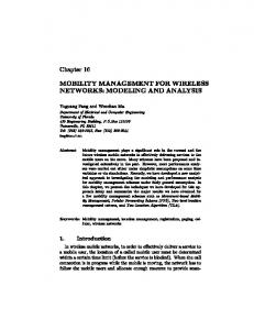
several issues still remain to be addressed, namely security, power consumption, routing, and QoS. In this paper, we propose the use of P2P paradigms for mobility management in the next generation of all-IP networks. To our knowledge, this area has been largely unexplored so far. Traditional mobility management solutions for all-IP networks, such as Mobile IP [6] and SIP Mobility [7], have a client / server topology. Hence, they suffer from the usual shortcomings of centralized solutions, such as single point of failures, bottlenecks, and risks of congestion. By bringing the benefits of P2P into mobility management, we hope to increase robustness, scalability, and availability. Thus, this work can be considered as an early attempt to use P2P concepts for mobility management in all-IP networks. The rest of this paper is structured as follows. In section II, we present some of the work in related areas. In section III, we explain the design of our P2P mobility management solution, and detail its operation. In section IV, we show some experimental results based on our proposed mobility model. In section V, we conclude this paper, and suggest future work. II. R ELATED W ORK As previously mentioned, there has been little work on using P2P concepts for mobility management in all-IP networks. However, the issues of P2P and mobility management have been extensively studied separately. In [1], we performed an extensive comparative analysis of all-IP mobility mechanisms, and evaluated the benefits of each proposed solution. Currently, the most popular solutions are network layer approaches built around Mobile IP [6], and application layer approaches built around SIP Mobility [7]. A. Mobile IP In Mobile IP [6], when a mobile node (MN) changes its subnet, it obtains a temporary Care-of-Address (CoA) from the foreign agent (FA) in the foreign network. Then, the MN informs the home agent (HA) of the obtained CoA, so the HA binds the permanent IP address (called Home Address) of the MN to its CoA. All packets addressed to the MN from a CN are routed to the home network, intercepted by the HA, and tunnelled to the FA. Figure 1 shows the Mobile IP scenario. B. SIP Mobility In SIP mobility [7], no FAs are needed, but the SIP Redirect Server (RS) plays the role of a HA. When the MN moves
home network
home network
MN
HA
data
MN: Mobile Node tunneled data
CN
MA HA
CN: Correspondent Node HA: Home Agent
FA data
data
FA: Foreign Agent
CN
Mobility Management using traditional Mobile IP
c MN
foreign network
1. 2.
1 CN
SIP INVITE
3 4
SIP 302 Moved 3.
SIP INVITE
4.
SIP 200 OK 5.
5
Data
foreign network home network
MN
RS
RS: Redirect Server 1. 2.
5
CN
2
4
SIP 200 OK 3.
1 3
SIP INVITE
4. MN
Data
SIP REGISTER
5.
SIP 200 OK
foreign network Fig. 2.
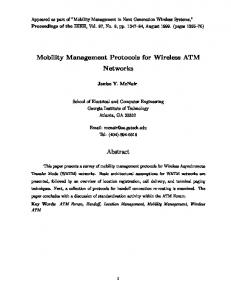
Mobility Management using traditional SIP Mobility
during a session, it must send a new INVITE to the CN using the same Call Identifier as the initial call. It must put the new IP address in the Contact field of the SIP INVITE message. This tells the CN where to send future SIP messages. Finally, the MN updates its registration information with the SIP RS in the home network. Figure 2 shows the SIP Mobility scenario. C. P2P Systems Peer-to-peer (P2P) [8] file-sharing applications have witnessed an explosive growth in the last years. However, P2P concepts are not limited to file-sharing applications, but can also be used in gaming, storage and processing applications. In P2P networks, the resulting interconnected set of peers forms an overlay network. P2P approaches can be categorized as: unstructured and structured. This depends on the placement of nodes in the overlay topology, and on how the lookup is performed to locate desired resources. For instance, Chord [9] is a structured P2P approach where peers are placed in a ring where their position is determined by a hash function. III. M -C HORD D ESIGN The goal of this paper is to introduce P2P concepts for mobility management in all-IP networks. Traditional approaches have mainly been client/server-based [6], [7].
MA CN
MA
MA
MN: Mobile Node CN: Correspondent Node HA: Home Agent FA: Foreign Agent MA: Mobility Agent
RS: SIP Redirect Server
RS
MA
P2P
FA
home network 2
MA
b FA
foreign network
MN
Fig. 1.
a
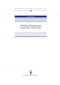
Fig. 3. Traditional (left) and Proposed (right) generic mobility management models for all-IP networks
A. m-Chord Topology Figure 3 shows a generic model representing the components involved in all-IP mobility management (HA and FA), as well as the endpoints of the IP session (MN and CN). In this paper, we propose to “virtualize” the functionality offered by HAs and FAs, into a distributed set of Mobility Agents (MAs). The MN and CN are still the same as in the traditional model, and the P2P topology of the mobility management components is transparent to them. Therefore, MAs form a P2P topology between themselves to exploit all the benefits of P2P. For instance, MAs should join and leave the network without affecting the operation. In this paper, the P2P overlay of MAs is based on the Chord [9] structured topology. Chord was chosen because of its simplicity, provable correctness, and performance. However, several modifications were introduced to the original Chord so that it becomes suitable for P2P mobility management in all-IP networks. This new Chord approach will be referred to as mChord for the rest of this paper. In m-Chord, the ring consists of MAs, where all MAs are fixed nodes playing the role of both HAs and FAs. These MAs usually have a high capacity to support connections from several MNs. m-Chord exhibits a hybrid topology, where the MAs with high capacity are part of the Chord ring, whereas some MAs with lower capacity. All wireless / mobile nodes connect to the MAs in the Chord ring following a Parent / Child relationship, commonly seen in hierarchical unstructured P2P topologies such as Kazaa [10]. The rationale behind this design is that MNs usually have low batteries, scarce bandwidth, and therefore, cannot relay packets indefinitely. By making the MNs connected to the ring of MAs, we avoid the issue of having MNs with limited resources relaying packets to other nodes. As for the fixed nodes connected to the ring of MAs, they can be promoted to become part of the ring if need be. The only situation where we would be forced to promote a MN to the ring will be if the number of MNs in the network exceeds the sum of the capacity of each fixed node available. We assume that this
situation has such rare occurrence that it could be neglected in the rest of the paper. Therefore, we can say that m-Chord is a one-hop wireless transmission solution, where the MNs communicate with their nearest MA in the Chord ring over a single hop to send and receive information.
MA
MA
Permanent Temporary
MA
Bootstrap
MA m-Chord
B. m-Chord Identifiers After explaining the topological design of m-Chord, we detail its operation. First, the issue of mobile nodes (MNs) identifiers is raised. In m-Chord, we use two identifiers for each MN. These identifiers are respectively, a Temporary Identifier, and a Permanent Identifier. The Temporary Identifier is, as its name suggests, temporary. It is related to the temporary IP address that a MN acquires in a foreign network when moving. The Permanent Identifier is, as its name suggests, permanent, and doesn’t depend on the location of the MN at a particular point in time. The temporary identifier is obtained by hashing the temporary IP address obtained by the MN when moving to a new foreign network. The temporary identifier is stored at the temporary mobility agent (MA) chosen based on the SHA1 hash results obtained by hashing the MN’s temporary IP address. This temporary MA becomes the parent MA to which the MN connects in the overlay. The permanent identifier is obtained by hashing a permanent identifier associated to the MN, which could be its MAC address. The permanent identifier is stored at the permanent mobility agent (MA), which is chosen based on the SHA-1 hash results obtained by hashing the permanent identifier. The permanent MA keeps a mapping between the permanent identifier, which is unique for each MN, and the temporary identifier, which changes when the MN’s IP address changes. Another mobility agent of importance is the bootstrap mobility agent (MA). The bootstrap MA is the MA which is physically close to the MN, and thus changes as the MN moves. It is essential to distinguish between physical and overlay proximity. The Temporary MA is “overlay” close to the MN, while the Bootstrap MA is “physical” close to the MN. Figure 4 shows the identifiers and their location in the m-Chord ring. C. m-Chord Motion and Lookup At the physical level, the MA in the foreign network, which we refer to as the bootstrap MA, advertises a new IP address using mechanisms similar to those in regular Mobile IP and other traditional mobility mechanisms, such as DHCP advertisements. In the overlay level, the MAs are assigned based on the value of the hash function applied to the temporary and permanent identifiers, where the MN connects to the temporary MA, which is its parent MA in m-Chord. When the MN moves, it is assigned a new temporary identifier, whereas the permanent identifier remains constant. Therefore, the permanent MA is usually the same, but the bootstrap and temporary MAs change with the MN motion. A mapping table needs to be kept updated at all times at the permanent MA, to point to the current bootstrap MA (physically close) of a particular MN whose permanent identifier is
Identifiers obtained by hashing
MA MA MA
MA MN
Overlay Physical
MA IP address acquired from Bootstrap MA
MN Fig. 4.
Identifiers in m-Chord
MA
MA
Permanent Old Temporary
MA MA
New Temporary Old Bootstrap
MN
New Bootstrap
MA Old Binding
MA MA
New Binding
MA
Overlay Physical
MA’
MA New IP address -> New temporary identifier
Motion
MN Fig. 5.
MN
Mobile node motion in m-Chord
stored at this permanent MA. The sequence of events, shown in Figure 5, is as follows: 1. The MN moves to a new foreign network, and detects its new IP address based on traditional mechanisms (DHCP), from a new MA playing the role of a bootstrap MA. 2. The bootstrap MA hashes the MN’s new IP address, and passes the obtained result to its new temporary MA, which stores it at its location in the ring, and the mobile node becomes the child of this temporary MA in the overlay. 3. The MN’s new bootstrap MA updates the mapping table stored at the MN’s permanent MA with the MN’s new bootstrap MA. The permanent identifier of the MN allows the new bootstrap MA to identify the permanent MA. The mapping table at the MN’s permanent MA contains two fields: . The sequence of events involved when a CN wishes to contact a MN, shown in Figure 6, is as follows:
MA
MA
Permanent Temporary
Parent CN 1
CN
MA
2
MA
Bootstrap
3
Physical
MA
4
MA MA
Fig. 6.
MA
MN
Mobile node lookup in m-Chord
1. The CN knows the MN’s permanent identifer. In mChord, the location of the MN is transparent to the CN at all times. Using the MA physically close to it, the CN queries the MN’s permanent MA for the MN’s current location. 2. The MN’s permanent MA is queried using the regular search procedure of Chord, based on the permanent MA’s identifier and the finger tables in all MAs along the way. 3. The MN’s permanent MA uses its mapping table to return the MN’s current location to the CN, which corresponds to the bootstrap MA which is physically connected to the MN. 4. The CN can now contact the MN directly through the bootstrap MA, which is the MA physically closest to the MN. Note that other background operations can be performed to refresh the information at the MAs in m-Chord’s ring. For instance, the binding table needs to be updated, as well as the finger tables at the MAs, which can change due to changes in the m-Chord ring. D. m-Chord’s Ring Modifications Most commonly, the ring of MAs changes when new MAs are added or when existing MAs fail, or when child MAs need to be promoted and added to the ring. 1. MA joins: When a MA joins the network, it needs an attachment point, i.e. another MA in the ring. Several methods exist for bootstrapping, but here we assume that a bootstrap MA is fixed, and serves as an attachment point for all MAs joining the network. Algorithm 1 shows the pseudo-code for the MA joining process. 2. MA is promoted: When a MA’s capacity is reached, and it has a MA as a child, it promotes that MA to become part of m-Chord’s ring. Algorithm 2 shows the pseudo-code for the MA promotion process. 3. Other Operations: Some operations are needed for both the MA joining and for the MA promotion operations. Algorithm 3 shows the pseudo-code for the operations needed for MA joining and promotion. E. P2P SIP Mobility If MNs in the network have a SIP User Agent, then these nodes can use the application layer to implement mobility in all-IP networks. In this situation, the permanent identifier is
Result: Join // MA m joins the network // MA m’ is an arbitrary MA serving as the bootstrap MA m.join(m’) if m’ then // MA m is not the first MA in the network //Find the location of MA m’ in m-Chord’s ring of MAs m’.find successor(m); else // If MA m is the only MA in the network for i=1 to n do // Fill in the finger table entries of MA m Finger[i].m = m; end // Set the predecessor of MA m to m predecessor(m) = m; end Algorithm 1: Pseudo Code for MA Joining
Result: Promote // Promote MA m knowing its successor promote(m,successor) // Initialize finger table of MA m using successor’s finger table as starting point m.initialize finger table(successor); // Update other finger tables m.update others(); move entries in (predecessor, m] from successor; Algorithm 2: Pseudo Code for Child MA Promotion
the SIP URI of a node. In traditional application-layer mobility solutions [7], two types of mobility are mentioned: Pre-call (before a call is established), and Mid-call (during a call). In Pre-Call mobility, the MN sends a SIP REGISTER message to its bootstrap MA. The SIP URI extracted from this SIP REGISTER message is hashed to obtain the permanent identifier for this MN. On the other hand, the IP address of the MN changes, hence is hashed to a new temporary identifier. When a CN wants to call this MN, it sends a SIP INVITE message to the MA that is physically closest to it. The ring of MAs is queried for the permanent MA, which uses its mapping table to determine the location of the MN corresponding to this permanent identifier, and returns the result to the CN using a SIP 302 Redirect message. The CN contacts the MN using a new SIP INVITE message with the current location. In Mid-Call mobility, the MN sends a new SIP INVITE message to the bootstrap MA, with its new IP address in the Contact field of the header. The new IP address is hashed, and the new temporary identifier is determined so that a new bootstrap MA is found to which the MN connects. The permanent MA is updated with the current location of the MN corresponding to each constant permanent identifier, as in the case of network layer mobility. From the To field of the SIP INVITE message header, the CN’s permanent identifier is extracted, and its permanent MA is found. This permanent MA identifier is inserted into the Via header of the SIP INVITE
Result: Find successor // Ask MA m to find the successor of a MA with identifier mid m.find successor(mid ) m’=find predecessor(mid ); return successor(m’) // Ask MA m to find m id’s predecessor m.find predecessor(mid ) m’=m; while mid ∈ (m’, successor(m’)] do m’ = m’.closest preceding finger (mid ); end return m’; // Return closest finger preceding mid m.closest preceding finger(mid ) for i=n to 1 do if finger[i].node ∈ (m, mid ) then end return finger[i].node; return m; end Result: Initialize finger table // Initialize finger table of local MA // MA m’ is an arbitrary MA serving as the bootstrap MA m.initialize finger table(m’) finger[1].node = m’.find successor(finger[1].start); // Insert MA m predecessor(m) = predecessor(successor(m)); // Set MA m as predecessor of successor predecessor(successor(m)) = m; for i=1 to n-1 do if finger[i+1].start ∈ [p , finger[i].node) then finger[i+1].node = finger[i].node; else finger[i+1].node = m’.find successor(finger[i+1].start); end end Result: Update others // Update all nodes whose finger tables refer to MA m m.update others() for i = 1 to n do // Find last MA m” whose ith finger might be m m’’=find predecessor(m − 2i−1 ); m’’.update finger table(m,i); end Result: Update finger table // If s is the ith finger of MA m, update m’s finger table with s m.update finger table (s, i) if s ∈ [m, finger[i].node) then finger[i].node = s; // Get first MA preceding MA m m = predecessor(m); m.update finger table (s, i); end Algorithm 3: Pseudo Code for other operations needed to Join and Promote
Main Street
Fig. 7.
Secondary Street
Cell
Physical Grid of Mobility Model
message, and the message is forwarded to the CN. The CN sends a 200 OK message back, and then data transfer can occur between the MN and the CN. IV. E XPERIMENTAL R ESULTS Experiments were conducted to study the performance of P2P in mobility management for all-IP networks. Unlike previous attempts to quantize mobility management performance, we will use implementations in the Network Architecture Labs at the University of Toronto, using IBM’s Blade Center with 56 blades consisting of 2 Xeon 2.8GHz processors each with 2GB RAM. The m-Chord implementation is written in the C language. In the following experiments, we do not measure absolute delays, since these numbers are not meaningful given that the MNs, CNs, and MAs used for these experiments are co-located and not physically distributed. The advantage of such a setting is that it does not depend on varying network conditions to affect absolute delay measurements, but rather calculates delays as a number of hops which allows fair comparisons. A. Mobility Model Traditional studies on mobility management use a randomwalk mobility model [11]. In this work, we try to emulate a real motion in a large city, such as Toronto, where streets are parallel, and consist of interleaved main and secondary streets, where speeds are different. This mobility model is novel, but we believe it portrays the real-world environment better than the random-walk model which assumes there is an equal probability for a mobile node to go in any direction. The network is viewed as a rectangular grid of cells, with the MN moving according to our new model between the adjacent cells. The speed of the MN is different between the main and the secondary streets. We assume that the speed of a MN on a main street is twice as much as that on the secondary street. Figure 7 shows the physical grid of the proposed model, where the motion is probabilistic. Motion depends on the type of street from where the MN is coming, and on the type of
intersection at which the MN is arriving. At the (Main Street Main Street) intersection, the probability of going back is zero, and that of taking any other direction is 13 . At the (Main Street Secondary Street) intersection, the probability of going back is zero, that of continuing straight is 12 , and that of turning left or right is 14 . At the (Secondary Street - Main Street) intersection, the probability of going back is zero, that of continuing straight is 15 , and that of turning left or right is 25 . At the (Secondary Street - Secondary Street) intersection, the probability of going back is zero, and that of taking any other direction is 13 . B. Measurement Metrics The different metrics to be measured are similar to those used in our original work [1]. These metrics are: 1) Handover Delay (HD): Quantifies the handoff delay. This delay has two main components: a) Mobility detection (which is the same for both Client/Server and P2P mobility management approaches), and b) Registration / Binding Delay. 2) Registration / Binding Cost (RC): Quantifies the registration / binding updates cost in the network. 3) Packet Delivery Cost (PDC): Quantifies the packet delivery cost in the network. These different metrics are dependent on the distances between the MN, the CN, and the MAs involved in the mobility management process. Without loss of generality, we will assume that the MN is moving, while the MAs and the CN are fixed. We assume each node has one session. We combine the registration / binding cost and the packet delivery cost into a new metric called Signaling Overhead Cost (SOC), which we introduced in [1]. SOC depends on the mobility rate of the MN (number of registrations needed), and on the number of active sessions that the MN is involved in (assumed one here). Unlike traditional mobility management, in m-Chord, delays and costs are due to operations at both the application layer and the physical / network layer. Even if the performance of mobility management using P2P concepts might result in higher costs in some situations, it still offers several advantages that outweigh these added costs: 1. No tunneling: A major disadvantage of Mobile IP is the need for data tunneling between home and foreign networks. 2. No triangular routing: Another disadvantage of Mobile IP was the need for packets to go through the home network before being sent to the foreign network, also known as triangular routing. 3. No single point of failure: An advantage of our P2P mobility management scheme is its added robustness, since the failure of single MAs does not result in the entire system to fail, since simple redundancy mechanisms could be used, such as having redundant storage kept at adjacent MAs. For Mobile IP, the values of the measurement metrics are (a and b correspond to the distances shown in Figure 3, and α corresponds the extra cost due to tunneling): 1) Handoff Delay (HD): We only consider the case when the MN is roaming. HD = 2b 2) Registration/binding Cost (BC):
BC = 2b 3) Packet Delivery Cost (PDC): The delivery cost depends on whether the MN is transmitting or receiving. CN to MN: PDC = a + b × (1 + α) MN to CN: PDC = c For the proposed P2P mobility management scheme, the values of the metrics are: 1) Handoff Delay (HD): We only consider the case when the MN is roaming. HD = 1 + 2 × dist(Bootstrap MA, Permanent MA) 2) Registration/binding Cost (BC): BC = 1 + 2 × dist(Bootstrap MA, Permanent MA) 3) Packet Delivery Cost (PDC): The delivery cost depends on whether the MN is transmitting or receiving. CN to MN: PDC = 2 + 2 × dist(Parent CN, Permanent MA) + dist(Parent CN, Bootstrap MA) MN to CN: PDC = 2 + dist(Bootstrap MA, Parent CN) For Mobile IP, the locations of CNs, HAs, and MNs are well known. Whereas for P2P mobility management, the distances between CNs, MNs, and MAs depend on the overlay topology, and on the physical distances, since lookups are needed in the overlay, depending on hashing identifiers. C. Results As mentioned previously, we implemented our P2P mobility management scheme using the C language. MN motion is emulated as the leaving, then joining at a new MA of a MN. We add the mobility model and the notion of physical location to our implementation. Therefore, when a MN moves to a new cell, the bootstrap MA assigned to it is chosen from the MAs in this cell. We implement the m-Chord mechanism and test its validity using up to 1000 nodes. The goal of these experiments is to study the performance of m-Chord for P2P-based mobility management. We cannot predict the values of the handover delay, and signaling overhead cost, because the location of the MAs is unknown, unlike Mobile IP where the HA’s and FA’s location are known. Thus, given a MN and a CN, an overlay search mechanism is performed when looking for the related MAs. In fact, the handover delay and signaling overhead cost for the P2P mobility management scheme are totally random. In order to attempt a fair comparison with Mobile IP, and without loss of generality, we start a MN in the center of the physical grid and choose a CN at a fixed location. We then move the MN around for a pre-determined duration at a pre-defined speed using the mobility model proposed. In each new cell the MN moves to, the metrics values are calculated, and their average is found after the motion ends. To find the best results possible, we repeat the experiment ten times, and again average the results obtained in each attempt. In these experiments, the physical grid size is set to 10×10 cells, with size 100 meters each. The speed of the MN is set to 20 m/s on a main street, and to 10 m/s on a secondary street. The number of MAs is set to 100, which are dispersed over the physical grid, such as each cell has one MA to which the MN can connect. Therefore, the
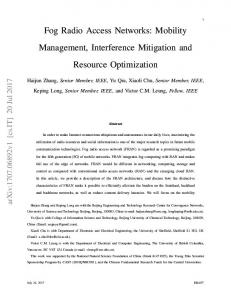
Handover Delay Comparison between Mobile IP and P2P Mobility Management
Signaling Overhead Cost Comparison between Mobile IP and P2P Mobility Management
Mobile IP P2P Avg P2P min P2P max 40
Mobile IP P2P Avg P2P min P2P max 45
35 40 30 25
35
20 30
15 10
25 5 0 20
20 20 20
15 15
10
20
15 15
10
10 5
10 5
5 0
CN−HA
0 MN−HA
Fig. 8.
Handover Delay
maximum distance between MN, CN, and MAs is 20 hops. Note that the diagonal motion of the MN is not allowed. Figure 8 shows a comparison of Mobile IP and P2P mobility management for handover delay. For Mobile IP, the handover delay depends on the distance between the CN and the HA, and on the distance between the MN and the HA. As mentioned previously, in our proposed P2P mobility management scheme, these distances are random. We draw the average value of the handover delay taken over these 10 experiments, as well as the minimum and maximum values. These values range from 10.5 hops to 16.5 hops, with an average of 13.2 hops. We observe that for high values of CN-HA distances, P2P mobility management, in addition to its other advantages, also offers better performance than traditional Mobile IP. Figure 9 shows this comparison for signaling overhead cost. For Mobile IP, the signaling overhead cost depends on the distance between the CN and the HA, and on the distance between the MN and the HA. As mentioned previously, in our proposed P2P mobility management scheme, these distances are random. We draw the average value of the signaling overhead cost taken over these 10 experiments, as well as the minimum and maximum values. These values range from 7 hops to 15.5 hops, with an average of 10.3 hops. We observe that P2P mobility management, in addition to the other advantages it provides, also offers better performance than traditional Mobile IP on average. V. C ONCLUSION In this paper, we have proposed a novel approach to mobility management based on P2P. This approach assigns two identifiers for each mobile node (MN): a permanent identifier and a temporary identifier. The permanent identifier is fixed regardless of the MN’s location, while the temporary identifier is constantly changing as the MN moves. The P2P overlay of mobility agents (MAs) is formed and the identifiers are stored
5 0
CN−HA
Fig. 9.
0
MN−HA
Signaling Overhead Cost
at the MAs according to their hash values. P2P provides several advantages over traditional mobility management schemes such as Mobile IP and SIP Mobility, and allows network layer as well as application layer mobility with the benefits that P2P brings. Experimental results have shown that P2P mobility management, despite the additional overhead due to the P2P lookup procedures, still outperforms in many situations the traditional schemes. Hence, the potential benefits of bringing P2P and mobility management together are important, and need to be further explored in the future to allow efficient all-IP mobility management schemes. R EFERENCES [1] R. Farha and A. Leon-Garcia, “Mobility Analysis for all-IP networks,” in Proceedings of the IEEE Wireless Communications and Networking Conference, vol. 3, pp. 1395–1401, Mar. 2005. [2] I.Clarke, O.Sandberg, B.Wiley, and T. W.Hong, “Freenet: A distributed anonymous information storage and retrieval system,” Proceedings ICSI Workshop Design Issues in Anonymity and Unobservability, June 2000. [3] M. Corson, J. Macker, and G. Cirincione, “Internet-based mobile ad hoc networking,” IEEE Internet Computing, vol. 3, pp. 63–70, July 1999. [4] S. Krco, D. Cleary, and D. Parker, “P2P Mobile Sensor Networks,” Proceedings of the 38th Annual Hawaii International Conference on System Sciences, pp. 1–9, Jan. 2005. [5] I. Akyildiz and X. Wang, “A survey on wireless mesh networks,” IEEE Communications Magazine, vol. 43, pp. 23–30, Sept. 2005. [6] C. Perkins, “IP Mobility Support for IPv4.” RFC 3344, Aug. 2002. [7] H. Schulzrinne and E. Widlund, “Application-Layer Mobility Using SIP,” ACM SIGMOBILE Mobile Computing and Communications Review, vol. 4, pp. 47–57, July 2000. [8] D. Liben-Nowell, H.Balakrishnan, and D. R.Karger, “Analysis of the evolution of peer-to-peer systems,” Proceedings of 21st ACM Symp. Principles of Distributed Computing (PODC), pp. 233–242, July 2002. [9] I.Stoica et. al., “A scalable peer-to-peer lookup service for internet applications.” MIT, Tech. Rep. TR-819, 2001. [10] J. Liang, R. Kumar, , and K. Ross, “Understanding Kazaa.” http://cis.poly.edu/ ross/papers/UnderstandingKaZaA.pdf, 2004. [11] Y. Wand et. al., “Performance Analysis of Mobile IP Extended with Routing Agents,” in Proceedings of the 2nd European IASTED International Conference on Parallel and Distributed Systems, July 1998.