UNDER PROJECTION. Paul L. Rosin & Geoff A.W. West§. Machine Vision ..... Barrow H.G., Tenenbaum J.M., "Interpreting Line. Drawings as Three Dimensional ...
PERCEPTUAL GROUPING OF CIRCULAR ARCS UNDER PROJECTION Paul L. Rosin & Geoff A.W. West§ Machine Vision Group Dept. of Electrical, Electronic, and Information Engineering City University London, EC1VOHB
Theories and techniques of shape constancy and shape from contour often assert that ellipses seen in an image are the 2D projection of 3D circlesfrom the scene. Given this assumption, several methods for grouping ellipses are described. From these perceptual groups inferences about the 3D structure of their generating circles are made. This will be useful for model invokation.
The world (both natural and man-made) is constrained by physical laws to a finite number of basic patterns. Certain three dimensional relationships between features in a scene give rise to two dimensional relationships that are relatively viewpoint invariant and can be distinguished as non-accidental. Thus, those regularities observable in the image arise not by accident, but are projections of real regularities in the scene. The Gestalt movement proposed that the human visual system applied the principles of perceptual organisation to group image features manifesting those regularities. These were used to recover three dimensional structure from two dimensional views, providing cues to models for scene interpretation. More recently, this technique has been applied within computer vision to reduce the search space required for object recognition. Marr [11] grouped elements of his primal sketch using perceptual groupings. Kanade [9] used parallelism and skewed symmetry to help interpret 2D shapes as 3D objects. Lowe [10] detected groups of straight lines, based on parallelism, colinearity and proximity, which then indexed the approximate pose of a 3D model in a scene. Mohan [12] generated a hierarchy of perceptual groups starting with parallel lines, then U shapes and finally rectangles. A stereo matching algorithm identified buildings in aerial images by matching similar groups. Biederman [3] recovered simple, convex generalised cylinders from perceptual groups within images for model matching. Most groupings considered by researchers have been based on dot patterns (e.g. [1]) or straight lines, although some work has been carried out on grouping curved lines [5]. The standard grouping laws of Gestalt theory [15] (i.e. proximity, similarity, closure, good continuation, and symmetry) are usually applied. *Now at Curtin University of Technology, Perth, Western Australia. 379
There are several specialised perceptual groupings that can be applied to ellipses in addition to the Gestalt laws. The principle assumption made is that ellipses detected in the image are generated by circular features in the scene. Given a 2D image curve, an infinite number of 3D curves exist that could project onto it. However, it is well known that the human visual system interprets ellipses as slanted circles and trapezoids as rectangles under perspective transformation. This phenomenon of shape constancy is mimicked by some techniques of shape from contour by defining additional desirable properties of the 3D figure such as smoothness [2] or compactness [4] which are maximised. Thus, there is some justification for at least making a tentative circularity assumption, which can be rejected during later image interpretation stages if incorrect. Assuming circularity, ellipses are first deprojected to form circles. Grouping is then performed on the basis of their 3D orientation and spatial location. Grouping straight lines is popular because they can be easily extracted by edge detection and polygonal approximation. Ellipses are more difficult to detect because of the increased number of parameters to be estimated. An advantage of ellipses over lines is that they contain more information and thereby further constrain the 3D interpretation. A single ellipse constrains the transformed circle to lie on a plane, with rotational symmetry around an axis through its centre perpendicular to the plane. An isolated line has many more degrees of freedom that can only be reduced by analysing combinations of several lines. If ellipses can be reliably detected then groups of ellipses are a powerful tool for visual perception. This paper briefly describes a technique for extracting ellipses from images. Several grouping rules specific to circles projected as ellipses are proposed, and examples of their application are shown.
ELLIPSE DETECTION After edge detection and Unking of the pixel data, ellipses are detected in images using a modified version of a two stage line and arc detection algorithm [14]. Initially a polygonal approximation to the data is found, after which a mixed polygonal and elliptical description is generated by replacing sequences of lines by ellipses if the ellipse is a BMVC 1990 doi:10.5244/C.4.67
better fit. Which is the best fit is determined by comparing the significance of the line description and the ellipse description. For a line the significance is defined as the maximum deviation (of the line from the pixel data) divided by the length of the line. The significance of the ellipse is defined as the maximum deviation (between the ellipse and the lines) divided by the length of the ellipse. The use of the significance measure gives an approximately scale invariant representation. The least-squares approach is used to fit ellipses to the polygon vertices rather than the complete pixel data. Computational speed is then reduced because of the reduction in the number of points. This method has the advantage that the choice between a line or ellipse representation does not need any threshold values.
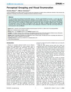
ELLIPSE PARAMETERISATION Ellipses are parametrised by centre location (r c ,v c ), length of the minor and major axes (a,b), and orientation of the major axis (6) in the image (see figure 1). The tilt angle (r) is calculated as described below. As the tilt tends to zero the ellipses become circular and the orientation becomes degenerate. The position of the centre detected by the ellipse finding algorithm is the correct centre for orthographic projection. For perspective projection, the centre is offset although the shape of the ellipse is correct. Our analysis assumes orthographic projection. The accuracy of the ellipse fit depends on several factors. Quantisation affects small ellipses which are either not detected or whose parameters are inaccurately estimated. Problems occur for short sections of ellipses whose parameters cannot be confidently estimated [13]. Experiments indicate that tilt angle (T) and major axis angle (8) are the most sensitive parameters, whereas the centre of the ellipse (xc,yc) is reasonably robust. The tilt angle of the ellipse is determined from the major and minor axis values. Assuming the ellipse is produced by a circle, the radius will be the major axis and the tilt will cause the minor axis to be less than the major axis. The tilt angle is:
validity of the first assumption depends on the environment: if only non-circular ellipses exist it will always be wrong, but if only circular ellipses exist is will always be correct. The real world contains a mixture of the two, and as such success cannot be guaranteed. However, the human visual system demonstrates that the assumption provides a workable solution to image interpretation, probably working in conjunction with additional evidence to confirm or reject the circle hypothesis. The second assumption is almost always correct since an accidental grouping would only exist over a small fraction of the viewsphere. When such degenerate views are encountered addition evidence would be needed to reject the apparent grouping. It has been shown that human subjects tend to misinterpret accidental groupings. For example, the Ames Chair, which is made up from disconnected and distorted components, is interpreted as a chair when seen through the peephole [8]. A number of perceptual groupings of ellipses are proposed. The grouping rules are detailed, and the 3D inferences that follow from each grouping are described.
Figure la. Parallel Planar
Figure 1c. Concentric
Figure lb. Solid of Revolution T =
The actual tilt angle will be ±T, i.e. two possible values as no knowledge is available as to the pose of the rest of the object(s). The accuracy of tilt angle measurement depends on a number of factors: the accuracy of the ellipse fit, the variation in position of each edge pixel due to noise and poor edge detection, and the actual tilt angle. The cosine expression is non-linear and small variations in the minor axis estimate at tilt angles near zero cause poor estimates of tilt angle. At tilt angles near 90° small variations have little effect. Since least square ellipse fits are biased towards high curvature the tilt will be consistently overestimated. Foster [7] showed experimental results for estimating the tilt of transistors from ellipse fits.
PERCEPTUAL GROUPINGS OF ELLIPSES The following perceptual groupings of ellipses are dependent on two assumptions generally holding true. 1) 2D ellipses are projections of 3D circles. 2) Certain configurations of ellipses usually arise non-accidentally. The
• Parallel planar: Ellipses that have the same major axis angle (6) and tilt angle (T) are probably lying on parallel planes (figure la). • Solids of Revolution: Ellipses with the same major axis angle (0), tilt angle (r) and whose centres lie on a straight line perpendicular to their major axes are most likely to be generated by a solid of revolution (figure lb). A solid of revolution is obtained by rotating a plane curve around a straight axis. An alternative hypothesis is that the ellipses are generated by coplanar circles lying on a straight line. • Concentricity: Ellipses with the same centre (JCC^C), orientation (8) and tilt angle (r) are probably generated by concentric, coplanar circles (figure lc). • Gestalt Grouping Laws: The standard grouping laws [15] of proximity, similarity, closure, good continuation, and symmetry can be applied to parallel planar ellipses. The case of the solids of revolution could be expanded to include generalised cylinders with circular cross-sections. It is straightforward to allow skewed cross-sections to be swept 380
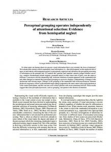
along a straight axis. The centres of the ellipses would then lie along a straight line with a constant angle between the line and their major axes. Curved axes are more problematic since the ellipses are no longer parallel planar, and will have differing tilt angles and orientations. If the axis is an arbitrary space curve almost any combination of ellipses could be interpreted as a generalised cylinder. This makes it useless as a significant perceptual group. Constrained axes such as circular arcs are more feasible although tilt and orientation still vary and computation would be expensive. Rather than test all combinations of ellipses, testing could be limited to subsets grouped using proximity or good continuation. These groupings are invariant over all viewpoints except the few cases in which the ellipses degenerate to straight lines or circles. Ellipses will not be detected if the viewpoint lies in the plane of the circle, and so no grouping can be performed. When the circles are viewed straight-on (and remain circular) their orientation is degenerate. They are still parallel planar, but no longer necessarily coplanar. All circles forming a solid of revolution will be concentric. It can be seen that the groupings form a hierarchy of increasing specialisation as shown in figure 2. As the groupings become more specialised groupings they are less likely to arise accidentally and constrain the 3D inference more, and are therefore more significant image structures. parallel planar
Gestalt grouping laws
angle. For solids of revolution, a two stage process is used. First, parallel planar ellipses are grouped as before. Then thepd Hough transform groups those ellipses whose centres lie on a straight line perpendicular to the major axis. In fact the second stage can use a one dimensional parameter space forp as the first stage has already grouped similar rotation angle. Reflectional symmetry is detected by hypothesising that the perpendicular bisector of the straight line between a pair of points is a line of symmetry. These lines are accumulated for all pairwise combinations of points. Points lying on the lines of symmetry are also taken into account. The effective bin size for the Hough transform is mainly dependent on the errors of the ellipse fitting. Other sources of error are quantisation, image noise, occlusion and image clutter and projective distortion. Orthogonal projection is assumed, but perspective projection will cause parallel planar ellipses to have different values of tilt. Also, the ellipse centres do not correspond to the projected centres of the circles. However, as the perspective distortion in the images is low, it is ignored in this analysis. In the following examples T was 0.2 radians and 6 was 0.5 radians. For concentricity the bin size for the position of the centre was set to 20 pixels for both X and Y directions. For solids of revolution reasonable results were obtained for a bin size for p of 40 pixels. A more general purpose approach to estimating bin size would be to probabilistically quantify the non-accidentalness of the grouping [10]. Currently, ellipses over the whole image are tested for mutual grouping. However, in complex, cluttered scenes it would be more efficient to limit the potential ellipses for inclusion in a group by some proximity measure determined by the sizes of the ellipse, the group and its elements.
surface of revolution
RESULTS concentricity
Figure 2. Hierarchy of Perceptual Groupings
We have described bottom-up groupings only. Their advantage is that they are domain independent, and therefore have a wide applicability. If application knowledge is available then more specific model-directed grouping rules can be applied. For example, Forsyth et al. [6] used the joint invariance values between pairs of coplanar ellipses to identify a particular configuration of ellipses seen from any viewpoint.
METHODS OF GROUPING All the ellipse groupings shown in the following examples (parallel planarity, solids of revolution, concentricity and symmetry) are implemented using the Hough transform. Instead of using an accumulator space the Hough transform formulations generate a linear array of parameters. Peaks are detected by performing a pairwise comparison of the array elements and incrementing a linear accumulator. For n ellipses this requires a search time of O(n2) which is efficient in this application due to the low number of ellipses detected in images. For parallel planar ellipses two parameters are used in the Hough transform: tilt angle and rotation angle. Therefore each element in the linear array has two parameters. The Hough transform for concentric circles uses four parameters: centre, tilt angle and rotation 381
Figure 3 shows the detection of two solids of revolution. The original image is shown with the grouped ellipses, their major axes and the axes of revolution overlayed. Figure 4 shows several concentric ellipses, their centre marked by a cross. In addition, the axis of revolution is shown. Figure 5 shows the detection of symmetric features in an image of coplanar ellipses. First, parallel planar ellipses are detected. To remove the distortion due to the angle of the object plane the ellipses are rotated about an axis parallel to the major axis by the tilt angle. This rotates the ellipses out of the plane, making the object plane parallel to the image plane. Figure 5a shows the detected ellipses and their coresponding centres after rotation. Reflectional symmetry analysis is then performed on the centre points of the ellipses to extract symmetric groups. Simple parallel symmetry analysis is sufficient because the effect of skew has been removed. Twenty symmetries are detected, two of which are shown in figures 5b and 5c. Figure 5b shows the best symmetry grouping, i.e. the grouping containing the largest number of ellipses. Most of the other symmetries detected contain only three ellipses. Some of these can be rejected because the sizes of the ellipses do not satisfy the similarity grouping rule. Figure 5c shows such an example in which one ellipse (ellipse 9) is smaller than both its symmetric pairings (ellipses 3 and 7). However, other symmetry groups cannot be rejected by this criterion, and form additional minor symmetries. Figure 5d shows the best line of symmetry and its associated ellipses remapped onto the original image.
Figure 3. Image with ellipses forming solids of revolution and the axes of revolution overlayed.
Figure 4. Image with the centre of the superimposed concentric ellipses marked by a cross.
Figure 5d. Image superim^' < i. *i/'i u line of symmetry and its associated ellipses.
REFERENCES
Figure 5a. Detected ellipses with their major axes, and their corresponding centres (crosses) rotated out of the plane.
1.
Ahuja N., Tuceryan M., "Extraction of Early Structure in Dot Patterns: Integrating Region, Boundary, and Component Gestalt", CVGIP, Vol. 48, pp 304-356, 1989.
2.
Barrow H.G., Tenenbaum J.M., "Interpreting Line Drawings as Three Dimensional Surfaces",v4/, Vol. 17, pp 75-117,1981.
3.
Biedennan I., "Matching Image Edges to Objects Memory", Proc. 1st. ICCV, pp 384-392,1987.
4.
Brady M., Yuille A., "An Extremum Principle for Shape from Contour", IEEE Trans. PAMI, Vol. 6, pp 288-301,1984.
5.
Dolan J., Weiss IL, "Perceptual Groupings of Curved Lines", Proc. DARPAIUW, pp 1135-1145,1989.
6.
Forsyth D., Mundy J.L., Zisserman A., Brown CM., "Projectively Invariant Representations using Implicit Algebraic Curves", Computer Vision - ECCV 90, O. Faugeras, ed., Springer-Verlang, pp 427-436,1990.
7.
Foster NJ., Sanderson A.C., "Determining Object Orientation using Ellipse Fitting", SPIE Intelligent Robots and Computer Vision, Vol. 521, pp. 34-43,1984. Ittelson W.H., The Ames Perception, Hafner, 1968.
Figure 5b. Best line of symmetry. Grouped ellipse centres are circled.
Figure 5c. A minor line of symmetry with inconsistent paired ellipses.
CONCLUSIONS This paper has proposed the use of perceptual groupings of ellipses for image interpretation. Several groupings are defined, based on the assumption that ellipses in the image are the 2D projections of 3D circles in the scene. These groupings are invariant over changes in viewpoint, and allow 3D inferences to be made. It is intended that they would be used as bottom-up cues for model invocation. Some examples are presented showing the grouping of ellipses extracted from images.
Demonstrations
in
9.
Kanade T., "Recovery of the Three-Dimensional Shape from a Single View", AT, pp 409-460,1981.
10.
Lowe D., Perceptual Organization and Visual Recognition, Kluwer Academic Publisher, 1985.
11.
Man* D., Vision, Freeman, 1982.
Mohan R., Nevatia R., "Using Perceptual 12.
Organization to Extract 3-D Structures", IEEE Trans. PAMI, Vol. 11, pp 1121-1139,1989.
13.
Porrill J., "Fitting ellipses and predicting confidence envelopes using a bias corrected Kalman filter", Image and Vision Computing, Vol. 8,1990.
14.
Rosin P.L.,West GA.W., "Segmentation of edges into lines and arcs", Image and Vision Computing, Vol. 7, pp 109-114,1989.
15.
Wertheimer M., "Laws of Organization in Perceptual Forms", in A Source Book of Gestalt Psychology, Ellis W.D, ed., Humanities Press, 1955.
382