Sep 2, 2011 - Toshimasa Miyazaki. â. Toukoku Ogata. â ... tracking control (PTC) system that uses a prediction state observer. Numerical simulation ... a digital feedback controller with a high-speed sampling ratio. [5],[6],[7] . However, this is ...
Preprints of the 18th IFAC World Congress Milano (Italy) August 28 - September 2, 2011
Perfect Tracking Control System using Prediction State Reference Observer for Optical Disk Kiyoshi Ohishi ∗ Toshimasa Miyazaki ∗ Toukoku Ogata ∗ Yuta Nabata ∗ Masaki Sazawa ∗ Daiichi Koide ∗∗ Yoshimichi Takano ∗∗ Haruki Tokumaru ∗∗ ∗
Nagaoka University of Technology, 1603-1 Kamitomioka-choNagaokaNiigata 940-2188Japan. ∗∗ Science and Technology Research LaboratoriesJapan Broadcasting Corp., 1-10-11 KinutaSetagayaTokyo 157-8510Japan Abstract: An optical disk drive system must realize high precision tracking control. For this purpose, the tracking control system that combined a robust feedback controller and a zero phase error feedforward tracking controllertracking control system has been proposed. This proposed feedforward tracking control system effectively suppresses the tracking error caused by track eccentricity. However, it is sometimes difficult for a conventional feedforward tracking control system to realize high precision tracking control. Hence, this paper proposes a new perfect tracking control (PTC) system that uses a prediction state observer. Numerical simulation results and experimental results confirm that the proposed system effectively suppresses the tracking error for a disk rotation speed of 8000[rpm] and operates stably. Therefore, the proposed system realizes high precision tracking control. Keywords: Optical disks, Tracking systems, Prediction error methods, Feedforward control, Observers 1. INTRODUCTION Recently, optical disk systems such as CD, DVD, and BD systems have become the standard for storage media. In the next generation optical disk systems, the track pitch becomes narrower than 0.01[µm] and the disk rotation speed becomes faster than 15,000[rpm][1],[2],[3],[4] . Therefore, the tracking control system for the next generation of optical disk systems should have a high precision performance and a wide bandwidth. The conventional tracking control system is a feedback control system which, has both a large DC gain and a high cut-off frequency. Generally, the tracking controller for an optical disk is a digital feedback controller with a high-speed sampling ratio[5],[6],[7] . However, this is difficult for a next-generation optical disk control system to achieve using only a feedback controller[3],[8] . On the other hand, repetitive control has been used successfully for precise tracking control[9] . However, with this system, it is difficult to maintain a robust parameter variation performance and the desired disturbance suppression response.[10] . In our previous work, a feedforward tracking control system is able to reduce the residual tracking error and maintain the tracking error under the condition of a high disk rotation speed. A feedforward control system is useful for compensating for the known periodic reference[11] . In an optical disk system, the reference value of the tracking control system is unknown. Thus, it has been difficult to apply the feedforward control system directly. The detect Copyright by the International Federation of Automatic Control (IFAC)
signal used by the tracking system is only the tracking error. The feedforward control system usually requests the reference signal for the servo system. In order to solve this problem, methods for predicting the tracking error have been proposed[8],[12],[13],[14],[15] . However, the conventional method for predicting the tracking error is complex, and the feedfoward control system requires a large number of operations. Thus, it is difficult to realize this tracking control system on a mass-produced optical disk system. This paper proposes a new prediction method for state references, which are used as the input signals of the PTC system. The proposed prediction method is construct based on a state observer. Numerical simulation results and experimental results shows that the proposed PTC control system with predictive state references effectively realizes the desired tracking servo performance using only the tracking error, in comparison with the conventional PTC system. The experimental system of this paper have a CDR specification, a disk rotation speed of 8000[rpm], and a sampling frequency of 120[kHz]. 2. PLANT MODEL OF VOICE COIL MOTOR As the target system, this paper uses a DDU-1000 optical disk system, which has a maximum disk revolution speed of 8000[rpm]. The plant system has both a first resonant frequency and a second resonant frequency. The actual plant system becomes fourth-order system P4 (s), as shown in (1). On the other hand, a simple plant system P2 (s) without including the second resonant frequency is defined
4034
Preprints of the 18th IFAC World Congress Milano (Italy) August 28 - September 2, 2011
6Ps2 + bs Dm − Km (7) Gp � 4Ps3 − bs Km + (4Ps3 − bs Km )2 − 4Kp Gp Ps4 cs = (8) 2Kp Gp � 4P 3 − bs Km − (4Ps3 − bs Km )2 − 4Kp Gp Ps4 ds = s (9) 2Kp Gp
as shown in (2). Fig.1 shows the frequency characteristics of these plant system. This paper considers both plant systems for designing the tracking controller.
Kp =
100
Magnitude (dB)
50 0 −50 −100
2nd order plant P2(s) 4th order plant P4(s)
−150 −200 0
The frequency characteristic of the open-loop system is shown in Fig.3. Its specifications are listed in TABLE 1.
a
−45
150
b
100
−180 −225
Magnitude [dB]
Phase (deg)
−90 −135
−270 −315 −360a 1 10
2
3
10
4
10
5
10
6
10
10
Frequency (Hz)
Fig. 1. Frequency characteristics of plant system
0 −50 −100
P4(z)*HGSC P2(z)*HGSC
−150b 0
5.43 × 10¹⁸ P4 (s) = 4 (1) 3 s + 947s + 3.55 × 10¹⁰ s2 + 1.57 × 10¹² s +6.87 × 10¹⁵
Phase [deg]
−45
7
P2 (s) =
50
−90 −135 −180 −225 −270
4.347 × 10 s2 + 259.9s + 4.458 × 10⁵
−315
(2)
−360 0 10
1
2
10
3
10
10
4
10
5
10
Frequency [Hz]
3. FEEDBACK CONTROL SYSTEM USING HGSC
Fig. 3. Frequency characteristics of open-loop system In this paper, the feedback controller for the optical disk tracking control system is constructed using a high gain servo controller[16] . The feedback controller for the optical disk tracking control system has an inverse high-pass filter and a phase-lead element. The structure of this feedback controller is similar to that of a conventional robust feedback controller. The block diagram of the feedback controller is shown in Fig.2. Gp P (s) = 2 (3) s + D m s + Km In order to design the feedback controller, the sensitivity function S(s) of the feedback control system is obtained as shown in (4). The desired sensitivity function Scomp (s) of the feedback control system is defined as shown in (5). The denominator polynomial coefficients of the feedback controller are determined by comparing (5) with (4). s(s − bs )(s2 + Dm s + Km ) S(s) = 2 s(s − bs )(s + Dm s + Km ) + Kp (s − cs )(s − ds )Gp (4)
s(s − bs )(s2 + Dm s + Km ) Scomp (s) = (s − Ps )4
Table 1. Performance of feedback control system
Perfect tracking control (PTC) is a type of feedforward control based on a multi-rate sampling control system[17] . It is a very useful control method for motion control applications. A PTC system for an optical disk system has already been proposed, as shown in Fig.4. �
(6) Controller
䠇
䞊
K ps
( s − cs ) s
Plant (s − d s ) ( s − bs )
P(s)
y (t )
142[dB] 8.78[dB] 38.0[deg] 6.67[kHz]
4.1 PTC-FF controller
P (z) =
y ref (t )
P4 (z)*HGSC
142[dB] 13.5[dB] 39.5[deg] 6.39[kHz]
4. PERFECT TRACKING CONTROL SYSTEM WITH PREDICTION TRACKING ERROR
(5)
bs = 4Ps − Dm
P2 (z)*HGSC DC gain Gain margin Phase margin Gain crossover frequency
A B C D
� (10)
This equation operates at sampling time Ts [sec]. The equation for the proposed multi-rate sample system becomes (11). �
Fig. 2. High Gain Servo controller system 4035
Am B m Cm D m
� =
Preprints of the 18th IFAC World Congress Milano (Italy) August 28 - September 2, 2011
�
Error Prediction
x(k + 1) =
etfbf ( k − N+n) N
� � � 0 0 1 x(k) + u(k) 1 −a0 −a1
y(k) = [ b0 b1 ] x(k) Gref (z)
LPF P (z )
PTC
�
�2 0 1 x ˜(i) −a0 −a1 � �� � 1 0 u(k) + −a1 1 u(k + 1) � � � � b0 y(k) b1 x ˜(i) = −a0 b0 b1 − a1 b0 y(k + 1) �� � � u(k) 0 0 + u(k + 1) b1 0
−1
z −1B m A m B m −1
MEMORY M ME EMORY
x ˜(i + 1) =
−1
z Cm
etfbf (k )
䋫 䊷
䋫
䋫
Dm
䋫
䋫
e0 (i )
I 0 (i ) 䋫
C (z )
䋫
䋫 䋫
y (k )
P (z ) 䊷
et (k )
y ref (k ) 䋫
Fig. 4. conventional error-prediction PTC system ⎡ ⎤ An An−1 B An−2 B · · · · · · B 0 0 ··· 0 0 ⎥ ⎢ C ⎢ CA CB 0 ··· 0 0 ⎥ ⎢ ⎥ ⎢ .. .. .. .. ⎥ .. ⎢ ⎥ . . . . ⎥ . ⎢ ⎣ CAn−2 CAn−3 B CAn−4 B · · · 0 0 ⎦ n−1
CA
CA
n−2
B CA
n−3
(11)
B · · · CB 0
I0 (i) = B−1 (I − z −1 A)xref (i + 1)
(12)
y0 (i) = z −1 Cxref (i + 1) + DI0 (i)
(13)
The PTC-FF system uses one sample forward state reference vector xref (i+1). The output of the tracking actuator is not measured for the tracking control of the optical disk system. It uses only the tracking error without a position reference. Therefore, it is difficult to realize the feedforward controller for the tracking control of the optical disk. In order to solve this problem, a tracking control system that used tracking error prediction is previously proposed, as shown in Fig.4. In the prediction of the tracking error, the reference signal of the tracking control system is the estimated tracking error on the condition of only the feedback control system as shown in (14) and, (15). xref (i + 1) = Gref (z)eft b (k − N + 2) =
et (k) +
eft b (k
− N)
(23)
The feedforward signals become the input variables of both the input side and the output side of feedback controller, as shown in (24) and (25). � M K(z) =
1 0 −a1 1
N K(z) = z −1
�
�−1
+ z −1
�
1 0 −a1 1
b1 b0 −a0 b0 b1 − a1 b0
�
�−1 �
� +
0 1 −a0 −a1 �
�2 (24)
0 0 M K(z) (25) b1 0
Therefore, the compensation signals in the robust tracking control system are calculated from (26) and (27). �
� � � If (k) xref (k) (26) = M K(z) ref If (k + 1) x (k + 1) � � � � ef (k) xref (k) (27) ef (i) = = N K(z) ref ef (k + 1) x (k + 1) If (i) =
(15)
The discontinuous system of plant system P2 (s), as shown in (2), becomes (28), which has a sampling time of 120[kHz].
4.2 PTC-FF for Second Order Plant System First, this paper will explain a PTC controller based on P2 (s). The discontinuous plant system P2 (z) at sampling time Ts is computed from (2) as shown in (17), (18), and (19). b1 z + b 0 P2 (z) = 2 (17) z + a1 z + a0
(21)
(22)
The state reference xref (k) is obtained from (23). � � � � eft b (k) xref (k) = Gref (z) f b xref (k + 1) et (k + 1)
(14)
Finally, the current command Icmd (k) for the tracking actuator is shown in (16). Icmd (k) = If (k) + C(z)(ef (k) + et (k)) (16)
(20)
In the prediction of the tracking error, the reference signal of the tracking control system is the estimated tracking error on the condition of only a feedback control system, as shown in (22). y(k) = eft b (k)
This paper uses a PTC-FF system based on the plant system. A multi-rate PTC-FF controller is designed for the plant system equations, as shown in (12),(13).
eft b
(19)
The multi-rate discontinuous plant system is shown in (20) and (21).
x refe (i + 1) z −n
(18)
P2 (z) =
0.00764z + 0.007639 z 2 − 2z + 0.9996
(28)
Gref 2 (z) is shown in (29).
4036
Gref 2 (z) =
z 0.00764z + 0.007639
(29)
Preprints of the 18th IFAC World Congress Milano (Italy) August 28 - September 2, 2011
���
10
���
5 voltage[V]
a6TCEMKPIa'TTQT=PO?
±0.126[nm]
�
0
̂���
−5 ̂��� ���
����
����
����
����
���
����
����
����
����
���
−10 0
a6KOG=UGE?
Fig. 5. result of conventional PTC system for 2nd order plant P2 (s)
0.002
0.003
0.004
0.005 0.006 Time[sec]
0.007
0.008
0.009
0.01
Fig. 6. result of conventional PTC system for 4th order plant P4 (s)
4.3 PTC for Fourth-Order Plant System
Table 3. pole of state command generator
Next, this paper explains the PTC controller based on P4 (s). The discontinuous plant system P4 (z) at sampling time Ts is shown in (30). c3 z 3 + c2 z 2 + c1 z + c0 z 4 + a3 z 3 + a2 z 2 + a1 z + a0
0.001
pole Gref 2 (z) Gref 4 (z)
0.99985 7.68825, 0.97618, 0.12564
(30)
Therefore, the conventional PTC-FF system is not applied to high-order plant systems.
The PTC controller for P4 (z) is described in terms of 4 × 4 matrices, as in the case of the second-order controller.
5. PERFECT TRACKING CONTROL SYSTEM WITH PREDICTION STATE REFERENCE OBSERVER
P4 (z) =
The discontinuous system of plant system P4 (s), as shown in (1), becomes (31), which has a sampling time of 120 [kHz]. P4 (z) =
0.001975z 3 + 0.01736z 2 + 0.01697z + 0.001863 z 4 − 1.411z 3 + 0.7329z 2 − 1.231z + 0.9097 (31)
In order to overcome this problem this paper proposes a new PTC-FF system with a prediction state reference observer. In the conventional PTC-FF system, Gref (z) becomes unstable. To obtain stable state references, this paper proposes the prediction state reference observer shown in (33). x ˆ(k + 1) = (A − hc)ˆ x(k) + bIcmd (k) + heft b (k) (33)
Gref 4 (z) is shown in (32).
The proposed observer is designed on the basis of a disz3 continuous plant system using the state observer method. Gref 4 (z) = 0.001975z 3 + 0.01736z 2 + 0.01697z + 0.001863 The proposed observer for a second-order plant system is (32) shown in (34). The proposed observer for a fourth-order plant system is shown in (35). These systems are capable 4.4 Numerical Simulation Results of having stable poles. In this paper, the poles of these observers are allocated to zero, which are dead-beat poles. In this paper, numerical simulations are performed to confirm the performance of the conventional PTC-FF control The proposed PTC-FF system is shown in Fig.7. � �� � � � system. The conditions for these numerical simulations are xˆ1 (k + 1) xˆ1 (k) 1 − h 1 b1 −h1 b0 listed in TABLE 2. = xˆ2 (k + 1) xˆ2 (k) −a0 − h2 b0 −a1 − h2 b0 Table 2. Condition of Numerical Simulation � � � � 0 h1 f b + I (k) + (34) e (k) Disk rotation Speed 8000[rpm] 1 cmd h2 t Reference of Track Sampling Frequency Track Eccentricity
sine wave 120[kHz] 100[µm]
5.1 Numerical Simulation Results
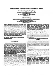
Fig.5 shows the numerical simulation results for the conventional PTC system for the second-order plant P2 (s). As shown in Fig.5, the residual tracking error is controlled stably and smoothly. Fig.6 shows the numerical simulation results for the conventional PTC system for fourth-order plant P4 (s). As shown in Fig.6, the residual tracking error is unstable. This is because Gref 4 (z) have an unstable pole, as shown in TABLE 3. In digital control theory, a high-order plant system has unstable zeros. The denominator of Gref 4 (z) is equal to the numerator of plant system.
In this paper, numerical simulations are performed to confirm the validity of the proposed PTC-FF system. The conditions for these numerical simulations are the same as those for the previous results, as listed in TABLE 2. As shown in Fig.8 and Fig.9, the proposed PTC-FF system suppresse the residual tracking error stably and smoothly. 6. EXPERIMENTAL RESULTS In order to confirm the validity of the proposed PTC-FF tracking control system for second-order plant system, this paper uses the tested optical disk system (DDU-1000), as
4037
Preprints of the 18th IFAC World Congress Milano (Italy) August 28 - September 2, 2011
I cmd ( k − N + n)
etfb ( k − N + n)
Prediction State Observer
LPF (z )
x ref (i + 1)
LPF (z )
PTC T
z −n
−1
z −1B m A m B m −1
MEMORY z −1Cm etfb (k )
MEMORY
䠇
I cmd (k )
䞊 䠇
䠇
Dm
䠇
䠇
I f (k )
e f (k ) 䠇
C (z )
䠇
䠇 䠇
feedback control system y (k ) P (z )
HGSC H HG SC
et (k )
䞊
䠇
y refe (k )
Fig. 7. proposed perfect tracking control system with prediction state reference observer ⎡ xˆ (k + 1) ⎤
⎡
−h1 b0 1 − h1 b1 −h1 b2 −h1 b3 −h2 b1 1 − h2 b2 −h2 b3 ⎣ xˆ2 (k + 1) ⎦ = ⎣ −h2 b0 xˆ3 (k + 1) −h3 b0 −h3 b1 −h3 b2 1 − h3 b3 xˆ4 (k + 1) −a0 − h4 b0 −a1 − h2 b1 −a2 − h4 b2 −a3 − h4 b3 1
a6TCEMKPIa'TTQT=PO?
���
⎤ ⎡ xˆ (k) ⎤ 1
⎡h ⎤ 1
⎦ ⎣ xˆ2 (k) ⎦ + ⎣ 0 ⎦ Icmd (k) + ⎣ h2 ⎦ eft b (k) (35) 0 xˆ (k) h 3
3
xˆ4 (k)
䣋䣥䣯䣦 ±0.092[nm]
���
⎡0⎤ 1
h4
䣇䣺䣲䣧䣴䣫䣯䣧䣰䣶䣣䣮䢢䣶䣧䣵䣶䣧䣦䢢䣵䣻䣵䣶䣧䣯 䣆䣆䣗䢯䢳䢲䢲䢲
䣕䣫䣩䣰䣣䣮 䣥䣫䣴䣥䣷䣫䣶 䣕䣶䣣䣴䣶䣫䣰䣩 䣥䣱䣰䣶䣴䣱䣮
䣒䣱䣹䣧䣴 䣃䣏䣒
� ̂��� ̂��� ���
����
����
����
����
���
����
����
����
����
���
䣆䣃䣅
a6KOG=UGE?
Fig. 8. result of proposed PTC system for 2nd order plant P2 (s)
䣖䣴䣣䣥䣭䣫䣰䣩䢢䣇䣴䣴䣱䣴
䣆䣕䣒䢢䣅䢷䢷䢲䢴
䣆䣫䣩䣫䣶䣣䣮 䣕䣫䣩䣰䣣䣮 䣋䣰䣲䣷䣶 䣃䣆䣅
䣆䣫䣩䣫䣶䣣䣮䢢䣕䣫䣩䣰䣣䣮䢢䣒䣴䣱䣥䣧䣵䣵䣫䣰䣩䢢䣄䣱䣣䣴䣦
Fig. 10. Block diagram of experimental tested system
���
a6TCEMKPIa'TTQT=PO?
±0.141[nm]
7. CONCLUSION
���
�
̂���
̂��� ���
����
����
����
����
���
����
����
����
����
���
a6KOG=UGE?
Fig. 9. result of proposed PTC system for 4th order plant P4 (s)
This paper proposes a new precision tracking control method based on a plant system with a prediction state reference observer. Table4 shows the numerical simulation results and experimental results. From Table4, the proposed PTC-FF system well suppresses the influence of periodic disturbance for high order plant system, stably and smoothly. The experimental results confirm that the proposed PTC-FF tracking control system effectively reduces the residual tracking error under the condition of a rotation speed of 8000[rpm].
shown in Fig.10. The proposed system uses a DSP(digital signal processor) with a sampling frequency of 120[kHz]. The experimental conditions used for the DDU-1000 CD system includes a disk rotation speed of 8000[rpm]. Comparing Fig.11 with Fig.12 shows that, the tracking error of the proposed system is decreased to ±9.40[nm]. Therefore, the proposed system decreases the tracking error to 80.0[%] that for the conventional PTC system. In particular, the proposed system effectively suppresses the tracking error for the fundamental frequency component at 133[Hz]. The experimental results confirm that the proposed system realizes high precision tracking control.
Table 4. Numerical simulation results and Experimental results
Conventional PTC-FF Proposed PTC-FF
Simulation P2 (s) P4 (s) 0.126[nm] Unstable 0.092[nm] 0.141[nm]
Experiment P2 (s) 11.83[nm] 9.40[nm]
REFERENCES [1] D.Koide, H.Tokumaru, K.Ohishi, T.Hayano, I.Shibutani and T.Miyazaki : “High-Speed Tracking
4038
Preprints of the 18th IFAC World Congress Milano (Italy) August 28 - September 2, 2011
I cmd(k)[A]
e t(t) [nm]
Servo Using ZPET-FF Method for Professional-Use Optical Disks Over 10000 rpm ”, ISOM 2006 Technical Digest CD, Mo-C-04, (2006). [2] D.Koide, Y.Takano, H.Tokumaru, N.Onagi, Y.Aman, S.Murata, Y.Sugimoto, K.Ohishi, “High-Speed Recording up to 15000 rpm Using Thin Optical Disk ”, Tech. Digest of ISOM2007, Tu-E-03, pp52-53, (2007). [3] T.Mukasa, N.Goto, T.Takasawa, Y.Urakawa, N.Tsukahara, “Stable Rotation of Optical Disks over 15000 rpm ”, Tech. Digest of ISOM2007, Tu-A-03, TD05-17(2008). 30 20 10 0 −10 −20 −30
28.63[nmp-p](μ±3σ=-0.05±11.83[nm])
0.3 0.2 0.1 0 − 0.1 − 0.2 − 0.3
200[msec/div]
(a) Wave form of tracking error and drive current 5
Amplitude [nm]
4 3 Fourth harmonics Second harmonics
2
Fundamental
1 0 101
102
103
Frequency [Hz]
104
(b) Frequency analysis of tracking error
Icmd(k)[A]
e t(t) [nm]
Fig. 11. Experimental result of conventional PTC system(8000rpm) 30 20 10 0 −10 −20 −30
23.71[nmp-p](μ±3σ=−0.05±9.40[nm])
0.3 0.2 0.1 0 −0.1 −0.2 −0.3
200[msec/div]
(a) Wave form of tracking error and drive current
Amplitude [nm]
4 3 2 1 0 1 10
Fourth harmonics Second harmonics Fundamenal 2
3
10
10
4
10
Frequency [Hz]
(b) Frequency analysis of tracking error
[4] D.Koide, Y.Takano, H.Tokumaru, N.Onagi, Y.Aman, S.Murata, Y.Sugimoto, K.Ohishi, “High-Speed Recording up to 15,000 rpm Using Thin Optical Disks ”, Jpn. J. Appl. Phys.Vol.47, pp.5822-5827, (2008). [5] K.Arai, H.Okumura, H.Tokumaru, K.Ohishi, “Improvement of Performance of a Tracking Servo System for an Optical Disk Drive”, Jpn. J. Appl. Phys.Vol.39, Part1, No.3B, pp.855-861, (2000) [6] T.Katayama, M.Ogawa, M.Nagasawa, “High-precision tracking control system for digital video disk players ”, IEEE Trans. Consumer Electronics, Vol.41, No.2, pp.313-321, (1995) [7] T.Yamaguchi, H.Numasato, H.Hirai, “A modeswitching control for motion control and its application to disk drives: Design of optical mode-switching conditions ”, IEEE/ASME Trans. on Mechatronics, Vol.3, No.3, pp.202-209, (1998) [8] K.Ohishi, T.Miyazaki, K.Inomata, H.Yanagisawa, D.Koide, H.Tokumaru, “Robust tracking servo system considering force disturbance for the optical disk recording system ”, Trans. on Industrial Electronics, vol. 53, no. 3, pp. 838- 847, (2006). [9] [8] C. Smith and M. Tomizuka : ”Shock Rejection for Repetitive Control Using a Disturbance Observer,” Proceedings of the 35th IEEE Conference on Decision and Control, pp.2503-2504, 1996. [10] D.Koide, H. Yanagisawa, H.Tokumaru, S. Nakamura, K.Ohishi, K.Inomata, T.Miyazaki, “High-speed Tracking Method using ZPET-FF Control for High-DataRate Optical Disk Drives ”, Tech. Digest of ISOM 2003, pp.40-41, (2003). [11] M.Tomizuka, “Zero Phase Error Tracking Algorithm for Digital Control”, ASME Journal of Dynamic Systems, Meas and Control, Vol.113, pp.6-10, (1987). [12] D.Koide, H.Yanagisawa, H.Tokumaru, K.Ohishi, Y.Hayakawa, “Feed-Forward Tracking Servo System for High-Data-Rate Optical Recording ”, Jpn. J. of Appl. Phys., Vol.42, Part1, No.2B, pp.939-945, (2003). [13] K.Ohishi, T.Hayano, T.Miyazaki, D.Koide, H.Tokumaru, “RRO Robust Following Control of Optical Disk Recording System Based on ZPET Control and Sudden Disturbance Observer ”, Proc.16th IFAC World Congress, We-A04-TP/13, Prague, (2005). [14] D.Koide, Y.Takano, H.Tokumaru, N.Onagi, Y.Aman, S.Murata, Y.Sugimoto and K.Ohishi:”A 252-Mb/s Recording Experiment Using Flexble Optical Disks for Broadcast Use”, IEEE. Trans. on Magnetics, Vol.45, No.5, pp.2190-2193, (2009) [15] Y.Kamigaki, K. Ohishi, T. Miyazaki, D. Koide and H.Tokumaru: ”Error Prediciton Robust Tracking Control System Suppressing Harmonic Disturbance for Optimal Disk Recording System”, Proc. of ISOM2009, Tu-G-10, pp.1-2, (2009) [16] Y. Urakawa and T. Watanabe: ”A Study of High-Gain Servo Controller with Complex Zeros for Optical Disk Drives”, Jpn. J. Appl. Phyns. Vol.44, No.5B, pp.34273431, (2005) [17] H. Fujimoto, Y. Hori and A. Kawamura: ”Perfect Tracking Control Method Based on Multirate Feedforward Control”, Trans. of SICE Vol.36, No.9, pp.766772, (2000)
Fig. 12. Experimental result of proposed system (8000rpm) 4039