has come to be known as the power wall; higher frequencies. *This research is supported in part by NSF grant 0702617, and grants from. Intel Corporation.
Performance and Power Optimization through Data Compression in Network-on-Chip Architectures∗ Reetuparna Das† Asit K. Mishra† Chrysostomos Nicopoulos† Dongkook Park† Vijaykrishnan Narayanan† Ravishankar Iyer‡ Mazin S. Yousif‡ Chita R. Das† † Dept. of CSE, The Pennsylvania State University ‡ Corporate Technology Group, Intel Corporation University Park, PA 16801 Hillsboro, OR 97124 {rdas,amishra,nicopoul,dpark,vijay,das}@cse.psu.edu {ravishankar.iyer,mazin.s.yousif}@intel.com
Abstract
lead to higher power consumption, which, in turn, spawned cooling and reliability issues. Furthermore, the exploitation of Instruction-Level Parallelism (ILP) through deep pipelining and complicated out-of-order superscalar cores seems to have reached a plateau: the inevitable and anti-climactic law of diminishing returns has set in. Architects have to look elsewhere to jump-start the quest for higher performance and frugal power envelopes.
The trend towards integrating multiple cores on the same die has accentuated the need for larger on-chip caches. Such large caches are constructed as a multitude of smaller cache banks interconnected through a packet-based Network-onChip (NoC) communication fabric. Thus, the NoC plays a critical role in optimizing the performance and power consumption of such non-uniform cache-based multicore architectures. While almost all prior NoC studies have focused on the design of router microarchitectures for achieving this goal, in this paper, we explore the role of data compression on NoC performance and energy behavior. In this context, we examine two different configurations that explore combinations of storage and communication compression: (1) Cache Compression (CC) and (2) Compression in the NIC (NC). We also address techniques to hide the decompression latency by overlapping with NoC communication latency. Our simulation results with a diverse set of scientific and commercial benchmark traces reveal that CC can provide up to 33% reduction in network latency and up to 23% power savings. Even in the case of NC – where the data is compressed only when passing through the NoC fabric of the NUCA architecture and stored uncompressed – performance and power savings of up to 32% and 21%, respectively, can be obtained. These performance benefits in the interconnect translate up to 17% reduction in CPI. These benefits are orthogonal to any router architecture and make a strong case for utilizing compression for optimizing the performance and power envelope of NoC architectures. In addition, the study demonstrates the criticality of designing faster routers in shaping the performance behavior.
The solution to thinning ILP gains has come in the form of the multi-core/CMP revolution. The enabler for this promising design paradigm is the steadfast shrinkage of technology feature sizes into the nanometer regime. By utilizing a number of simpler, narrower cores on a single die, architects can now provide Thread-Level Parallelism (TLP) at much lower frequencies. The presence of several processing units on the same die necessitates oversized L2 and, where applicable, L3 caches to accommodate the needs of all cores. Burgeoning cache sizes are easily facilitated by the aforementioned explosion in on-chip transistor counts. However, the implementation of such large cache memories could be impeded by excessive interconnect delays. While smaller technology nodes are associated with shorter gate delays, the former are also responsible for increasing global interconnect delays [1]. Therefore, the traditional assumption that each level in the memory hierarchy has a single, uniform access time is no longer valid. Cache access times are transformed into variable latencies based on the distance traversed along the chip, and has spurred the Non-Uniform Cache Architecture (NUCA) [8] concept. A large, monolithic L2 cache is divided into multiple independent banks, which are interconnected through an on-chip interconnection network. What can clearly be surmised from the NUCA mechanism is the enormous strain placed on the interconnection backbone. The network fabric undertakes the fundamental task of providing seamless communication between the processing cores and the scattered cache banks. Although its intricacies are often ignored or underestimated, the on-chip interconnect in large NUCA-based CMPs is of utmost importance. Most prior work in CMP NUCA designs uses a packet-based Network-on-Chip (NoC) [11] architecture. Widely viewed as the de facto solution for integrating the many-core architectures, NoCs are be-
1. Introduction The last few years have witnessed a major upheaval in microprocessor architectures. The relentless increases in clock frequencies that shaped the scene in the late 1990s and early 2000s have almost come to a standstill. Architects hit what has come to be known as the power wall; higher frequencies ∗ This research is supported in part by NSF grant 0702617, and grants from Intel Corporation.
978-1-4244-2070-4/08/$25.00 ©2008 IEEE
215
coming increasingly popular because of their well-controlled and highly predictable electrical properties and their scalability. However, research in NoC architectures clearly points to some alarming trends; the chip area and power budgets in distributed, communication-centric systems are progressively being dominated by the interconnection network [35]. The ramifications of this NoC dominant design space have led to the development of sophisticated router architectures with performance enhancements [19, 26], area-constrained methodologies [21], power-efficient and thermal-aware designs [31], and fault-tolerant mechanisms [29]. Cache Compression Scheme (CC)
NIC Compression Scheme (NC) NUCA L2 Network
CPU Node
CPU Node
NUCA L2 Network
CPU
Compressed Data & Compressed Traffic
L1 Comp/ Decomp
NIC
Cache Bank Node
L2 Uncompressed Data
L2
Compressed Data
L1
Comp/ Decomp in NIC
NIC
R
Uncompressed Data but Compressed Traffic
CPU
Uncompressed Data
Cache Bank Node
Compressed Data
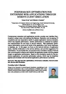
banks, with only the network communication traffic being compressed. A simple compressor/decompressor module can be integrated in the NIC to facilitate this technique. The NC scheme has the important advantage that it does not require any modification in the L2 cache banks. This attribute affords NC plug-and-play capability, which is crucial in modern Systemon-Chip (SoC) implementations that comprise several Intellectual Property (IP) blocks from various vendors. In many cases, these IP blocks may not be modified (known as hard IP cores); CC would, therefore, not be applicable in such environments. Moreover, the inclusion of NC in this study aims to characterize and quantify the effect of compression purely in the NoC of a NUCA CMP. On the downside, NC requires a compressor/decompressor unit in the NIC of every node in the network, as can be seen in Figure 1. This is in contrast to the CC scheme, which requires such units only in the CPU nodes. It will be shown that the additional area and power overhead is minimal, since the compressor/decompressor unit is very lightweight. However, performance is also affected because the NC mechanism involves compression and decompression operations for both read and write requests, while CC involves only one of the two operations for a given memory request (decompression for reads, compression for writes). To mitigate the performance overhead of decompression, we overlap the decompression phase with network traversal. This mechanism hides some of the decompression latency overhead by commencing progressive decompression as soon as the header flit of a packet reaches its destination NIC. To facilitate a complete system evaluation, including processor, memory and NoC systems, we have developed an integrated NoC/cache simulator for CMP architectures. We have used a diverse set of benchmarks, ranging from scientific applications to commercial workloads, for in-depth performance analysis on 8- and 16-core systems with varying number of L2 banks, connected through a 2-D mesh. Overall, the major contributions of this paper are the following:
R
Comp/ Decomp in NIC
R
Compressed Traffic
R
Figure 1. Cache Compression (CC) and NIC Compression (NC) schematic
While all prior studies have exploited the router microarchitecture design for optimizing the NoC performance and power envelope, the essence of this paper revolves around the idea of employing data compression [5, 6, 33, 17] for additional gain in performance and power. The effect of compression on the interconnection network of NUCA-based CMPs is currently not clear. Toward that extent, this work analyzes the impact of compression on the underlying NoC. The ramifications on network performance, router complexity, buffer resources, and power consumption are investigated in-depth by conducting a series of experiments involving the major architectural components of a typical NoC router. Intuitively, data compression would reduce network load, and, in effect, lower average network latency and power consumption, leading to application level performance improvement. The motivation of this paper is to quantify this gain for critical design decisions. In this context, we explore two data compression techniques for NUCA-based CMP systems, as illustrated abstractly in Figure 1. The two techniques explore combinations of storage and communication compression. The first scheme, known as Cache Compression (henceforth abbreviated to CC), compresses data after the L1 cache, prior to sending it to a shared L2 cache bank (i.e. compression benefits both storage and network communication). Compressing data in the cache is a technique aimed at improving memory and, ultimately, system performance by squeezing more information into a fixed-size cache structure. The second scheme, called Compression in the NIC (abbreviated to NC), employs compression at the Network Interface Controller (NIC), prior into injection in the network. NC implies the use of uncompressed storage data in the cache
• First, to the best of our knowledge, this is the first work to comprehensively characterize and quantify in detail the effect of data compression on the on-chip network of a NUCA-based CMP. The effects of both CC and NC schemes on the network behavior are analyzed in terms of average network latency, power consumption, and buffer utilization. We also extend the analysis to estimate the benefits at the application level. • Overall, the CC scheme provides on an average 21% reduction in network latency with maximum savings of 33%. Similarly, power consumption is reduced by an average of 7% (23% maximum). At the application level, we observe, on an average 7% reduction in CPI compared to the generic case. • The NC scheme on an average provides network latency reduction of 20%, (32% maximum), while power consumption reduces on an average by 10% (21% maximum). The novelty of this scheme is that it does not need any
216
Zero 16Bit 8BitRepeated
4Bit 16BitPadded Uncompressed
8Bit 16BitHalfSE
variable-length compression method. This implies that decompression cannot be done in parallel, and the cache set structure is complicated due to the variable length cache lines. Cache compression allows to store more data in the same cache size. This can be achieved by using higher associativity for the same physical set size and by additional hardware to handle variable cache line sizes in every set. A cache architecture to handle variable length cache lines is depicted in Figure 3(a). In this design, the traditional hardware granularity of one cache line is now reduced to a segment within a set. As in [5], one segment consists of 4 compressed words with one set containing 32 segments. Each cache line may consist of one to eight segments, depending on its compressibility. The tag is thus modified to accommodate a 3-bit length value (i.e. up to 8 cache lines). We use a 1-bit compression status flag indicating whether the line is compressed or not. Although in this work we do not use the adaptive scheme of [5], we still use this bit to optimize the on-chip interconnect throughput by sending the uncompressed packet over the interconnect without the tag, if none of the words were compressible in a particular cache line. The additional hardware modules required to enable the use of the cache compression scheme are shaded in Figure 3(a). The critical path for a cache lookup is also shown in detail in the adjacent flow graph (the additional modules in Figure 3(b) are shaded in grey). Every cache line starts at a variable segment offset from the start of the set, depending on the cumulative length of all previous valid cache lines. Therefore, the start address of each cache line needs to be computed. A parallel prefix adder is employed for this purpose. The adder can operate in parallel with the tag comparators. Since the granularity of a cache line has been reduced to a variable number of segments, a cache line can now potentially start from any segment offset in the set (each set has 32 segments) and, similarly, end at any segment. Hence, the straightforward output from the tag comparators can no longer be used to drive the output driver multiplexer circuits [32]. Instead, the monolithic output driver circuits must be broken into many smaller drivers to account for the increased segment granularity in each cache line. These drivers are controlled by a 32-bit controlling mask, with each bit representing one segment in the entire set. A bit-mask generator is, thus, added to the circuitry, which takes the cumulative length and current length as inputs to generate a bit-mask that will activate only those segments belonging to the valid matched cache line. The bit-mask is subsequently fed to the data output driver circuits. In order to support variable-line size, the tag array access and data array access components need to be decoupled, as in [15, 34]. Further, contiguous storage invariant needs to be maintained at all times. This is required to avoid any internal fragmentation within the set, and, more importantly, to simplify the data-array lookup. If holes of invalid segments are allowed to permeate the valid cache lines, then the system would need to keep track of the starting addresses of each valid cache line in addition to the line length. To maintain a contiguous storage space, segments within the cache set must be moved when certain events occur. We call the operation of moving
100% 80% 60% 40% 20% 0%
Figure 2. Data Pattern Breakdown
modifications to the cache architecture and can be adopted in generic SoC/multi-core platforms. • Finally, a direct corollary of this analysis is the very interesting conclusion that existing NoC architectures are so elaborate and over-designed that they do not adequately match the speed of the processing cores. This mismatch in speed is detrimental to the overall performance. Instead, lean and lightweight on-chip routers are preferred in terms of operating frequency and they can over-compensate for any lack of sophistication. The rest of the paper is organized as follows: Section 2 presents the two compression schemes to be investigated in this paper; the experimental platform and workload used in this study are presented in Section 3; Section 4 is devoted to performance evaluation and, summary of related work is presented in Section 5. Finally, the concluding remarks are drawn in Section 6.
2. Compression Techniques 2.1. Cache Compression Cache compression is a well-studied technique and researchers have used various compression techniques over time [37, 5, 23]. The current state-of-the-art compression design uses frequent-pattern compression [4], which is a significancebased compression scheme. It compresses some frequent patterns such as consecutive 0s and 1s in data streams. In our investigation of the workloads, we observed a few patterns occurring with very high frequencies, as illustrated in Figure 2, corroborating the effectiveness of the aforementioned compression technique. For example, as shown in Figure 2, applications like apache, ocean and zeus have more than 60% of consecutive 0s, while on the other hand, applications such as mgrid and swim have very little frequent patterns, rendering them mostly uncompressible. The advantage of this frequentpattern compression method is that high compression ratios can be achieved. The disadvantage, however, is that the scheme is a
217
START
BIT LINES WORD LINES
ADDRESS INPUT ADDRESS DECODER
TAG ARRAY
COLUMN MUXES
SENSE AMPS
START LEN. SEL. MUX
8x5 START SEG.
NO
YES
SEGMENT COLUMN MUXES
LOCK SET PARALLEL PREFIX ADDER
COMPARE TAGS
COMPACT
8x3 CSIZE
COMPARATORS
MUX DRIVER
CSIZE SELECT MUX 3 BITS
5 BITS
BIT MASK GEN. (32 BITS)
OUTPUT DRIVER
WORD LINES
DATA ARRAY
SENSE AMPS
PARALLEL PREFIX ADDER
COMPACTION DETECTION
ADDRESS DECODE, WORD LINE SELECT, BIT LINE SELECT AND SENSE AMPLIFIER
BIT LINES
UNLOCK SET
OUTPUT DRIVERS
32 BITS
VALID OUTPUT
SEGMENT BIT MASK GENERATOR
DATA OUTPUT
(a) Cache Model
DATA OUTPUT DRIVER
EXIT
(b) Cache Lookup Algorithm
Figure 3. Cache Configuration To Support Variable Line Size DECOMPRESSION CYCLES
segments within the set compaction. Compaction is needed under two circumstances: (1) On a write hit, and when the data to be written back is larger than the original compressed line (fat write) and (2) On a replacement, and when the line chosen to be replaced is not the exact same size as that of the fresh line being brought into the set. Note that more than one line may need to be replaced to accommodate a new line. This process may require more than one compaction operation. Before the compaction operation commences, the set needs to be locked and cannot service further requests. Compaction is not on the critical delay path, as the processor is not stalled for a write, and, in the case of a miss, the fetched data is sent back immediately while the set is simultaneously locked to prevent further access. However, the locking of the set may cause performance degradation since the set is no longer available until compaction is complete. Fortunately, our experiments indicate that the number of compactions required is relatively low, and the time period between consecutive compactions is large enough to accommodate the compaction time. Our experiments show that the average number of cycles between two consecutive compactions to a bank is around six thousand cycles with a minimum of around two hundred cycles. Compaction needs two additional hardware modules(not shown in Figure 3(a)): a Compaction Detection Module, and a Compaction Buffer of the size of one set. A single compaction operation will first require a read from the set, followed by two writes to the set. To limit the area overhead imposed by the compaction scheme, only one set buffer per cache bank is used; thus, the buffer needs to be shared by all sets in the bank. In order to read/write data from the set during a compaction operation, the column decoder logic needs to be coordinated by the Compaction Detection Module to enable the right segments for read and write-back to the set. The area overhead for compression in a cache bank has been calculated in [5] to be approximately 7%, but without taking into account the compressor/decompressor circuit. In our analysis, we have accounted for cache compaction and additions to the basic cache structure in order to investigate the impact on access time. The additional compaction buffer per bank
CYCLES
0
1
2
3
4
5
6
0
1
2
3
4
5
6
7
8
9
TO L1/ PROCESSOR
FLITS
TO L1/ PROCESSOR
CYCLES FLITS
SAVINGS PER MSG. PRECOMPUTATION (STAGES 1,2 & 3)
STAGES 4 AND 5
Figure 4. An Example Time Line for a Five Flit Message
(size of one set), adds a minimal 0.1% overhead. To calculate the timing overhead, the baseline cache timing parameters were taken from CACTI 4.2 [32] and the additional modules including compressor/decompressor circuit were implemented in Verilog, synthesized in 90 nm and scaled to 45 nm [9]. The additional modules add 0.41 ns to the critical path. This requires two additional clock cycles for each cache access to support a variable line, segmented cache for a 4-GHz processor. This result is significant, because it shows that cache compression does, indeed, affect the cache access time. The area overhead and dynamic power consumption of the compressor/decompressor circuit from our implementation were found to be 0.183 mm2 and 0.273 W, respectively.
2.2. Compression in NIC For architectures that do not employ cache compression, we can use compression in the NIC prior to injecting traffic into the network. This scheme needs a compressor and decompressor in each NIC, and thus, adds to the area and timing overheads. In this paper, we show that some of the compression and decompression latency can be hidden by utilizing a pipelined router design. Frequent-pattern compression can be realized in five cycles [4]. In the first cycle, the length of each word is decoded using the prefix tags. In the next two cycles, the starting bit address of each word is computed by cumulatively adding the length bits of each word. In the fourth and the fifth cycles, a parallel pattern decoder decodes the contents of the compressed
218
Baseline Simulation Configuration Processor Cores Eight Processors at 4GHz clock Private L1 Cache Split I and D cache, each 32KB,4-way set associative, 64B line,3-cycle access time Shared L2 Cache Unified 4MB with 16 256KB bank, each bank 4 cycle access time uncompressed 4+2(access time overhead)+5(decompressor overhead)cycles for compressed Memory 4GB DRAM,400 cycle access,each processor up to 16 outstanding memory requests Router Pipeline 2-stage,wormhole routing, 2 VCs per PC,80-bit flits, 4 flits buffer depth
3.1. Baseline CMP Architecture Without loss of generality we assume an 8-core CMP at 45 nm technology size as our baseline architecture. Each core has split private L1 cache (instruction and data cache each 32 KB in size). All the cores share the 4 MB last level cache (L2). The L2 cache is split into 16 banks, each of size 256 KB. A 6x4 mesh network( as shown in Figure 5) connects these banks. Each L2 cache bank has a router associated with it. Each router connects to four adjacent routers in the four cardinal directions. The detailed configuration is given in Table 1. We implemented a detailed trace-driven cycle-accurate hybrid NoC/ cache simulator for CMP architectures. The memory hierarchy implemented is governed by a two-level directory cache coherence protocol. Each core has a private write-back L1 cache. The L2 cache is shared among all cores and split into banks. Our coherence model includes a MESI-based protocol with distributed directories, with each L2 bank maintaining its own local directory. The simulated memory hierarchy mimics SNUCA [8]. The sets are statically placed in the banks depending on the low order bits of the address tags. The network timing model simulates all kinds of messages: invalidates, requests, replies, write-backs, and acknowledgments. The interconnect model implements a state of art low-latency packet-based NoC router architecture. The NoC router adopts the deterministic X-Y routing algorithm, finite input buffering, and wormhole flow control. The power estimates extracted from the synthesized implementations are also fed to the simulator to compute overall power consumption.This platform is used in conjunction with the Simics full system simulator [25], which is used as memory reference generator. All the additional hardware logic mentioned in this paper was implemented in structural RegisterTransfer Level (RTL) Verilog and then synthesized in Synopsys Design Compiler using a TSMC 90 nm standard cell library. The library utilized appropriate wire-load approximation models to reasonably capture wire loading effects. The area and power numbers then obtained were scaled down to 45 nm technology [9].
Table 1. Simulation Model
P
P
P
P
I D
I D
I D
I D
I D
I D
I D
I D
P
P
P
P
Figure 5. Baseline CMP Layout
data bits into uncompressed words using their respective prefix bits. This overhead is on the critical path of the L2 hit latency. Prior work has tried to reduce this latency by an adaptive scheme based on the LRU stack depth in the cache [5]. Here, we present an optimization based on the observation that in a packet-based network, it is possible to overlap the decompression with the network latency. The decompression pipeline can be designed such that we need not wait for the entire cache line to arrive before we can start the decompression phase. Since at the ejection port we can get at most one flit per cycle in a wormhole switched network, decompression may commence as soon as the header flit of the compressed cache line arrives. This flit contains the prefix tags and all the necessary information for the first three stages of the decompression pipeline. After the tail flit arrives at a NIC, we can complete the final two steps of the decompression stage and commit the data to the L1 cache and/or processor. This technique will save three clock cycles per decompression operation, effectively reducing the overhead from 5 cycles to 2 cycles. Figure 4 demonstrates the three cycle saving that can be accrued from the proposed scheme.
3.2. Baseline Router Architecture A generic NoC router architecture is illustrated in Figure 6. The router has P input and P output channels/ports. In most implementations, P=5; four inputs from the north, east, south and west directions, and one from the local Processing Element (PE). The Routing Computation unit, RC, is responsible for directing the header flit of an incoming packet to the appropriate output Physical Channel/port (PC) and dictating valid Virtual Channels (VC) within the selected PC. The routing is done based on destination information present in each header flit, and can be deterministic or adaptive. The Virtual channel Allocation unit (VA) arbitrates amongst all packets requesting access to the same VCs and decides on winners. The Switch Allocation unit (SA) arbitrates amongst all VCs requesting access to the crossbar and grants permission to the winning flits. The winners are then able to traverse the crossbar and are placed on the output links. Simple router implementations require
3. Experimental Platform In this section, we describe our complete CMP platform including the processor core and the underlying NoC architecture, the router model and the workloads used for the performance analysis.
219
TPC-W: We use an implementation of the TPC-W benchmark [2] from New York University consisting of two tiers - a JBoss tier that implements the application logic and interacts with the clients and a Mysql-based database tier that stores information about items for sale and client information - under conditions of high consolidation. It models a online book store with 129600 transactions and 14400 customers. Java ServerWorkload: SPECjbb. SPECjbb2000 is a Java based benchmark that models a 3-tier system. We use eight warehouses for eight processors, we start measurements 30 seconds after rampup time. Static Web Serving: Apache. We use Apache 2.0.43 for SPARC/Solaris 10 with default configuration. We use SURGE [7] to generate web requests. We use a repository of 20,000 files (totalling 500 MB). We simulate 400 clients, each with 25 ms think time between requests. Static Web Serving: Zeus. Zeus is the second web server workload we used. It has an event-driven server model. We use a repository of 20,000 files of 500 MB total size, 400 clients, 25 ms think time. SPEComp: We used SPEomp2001 as another representative workload. We present the results from apsi, art, mgrid and swim due to space constraints. SPLASH 2: SPLASH is a suite of parallel scientific workloads. Each benchmark executed sixteen parallel threads running on a eight way CMP. Mediabench (mm). We use eight benchmarks (cjpeg, djpeg, jpeg2000enc, jpeg2000dec, h263enc, h263dec, mpeg2enc and mpeg2dec) from the Mediabench II [3] suite to cover a wide range of multimedia workloads. We used the sample image and video files that came with the benchmark. For throughput computing we simultaneously executed all benchmarks on each individual core for 30 back-to-back runs.
VC Identifier VC 1 Input Channel 1
VC 2
Routing Unit (RT) VC Allocator (VA)
Credit out VC v Input Port 1
Credits in
Switch Allocator (SA)
Output Channel 1 Input Port P
Input Channel P
Output Channel P
Credit out Crossbar (P x P)
Figure 6. A Generic Router Architecture
larger technology nodes. Even after scaling to 45 nm technology [9], the single-stage router of [27] can reach only about 1 GHz. The router in [12] can reach 2 GHz, but it is deeply pipelined (5-stage router). However, various CMP designs [8, 6] demonstrate a processor clock speed within 5 to 10 GHz. We analyzed the router pipeline to discover that the arbitration stage is the bottleneck of the pipeline, and this stage determines the clock frequency. We also observed from our circuit-level implementation and timing analysis that reducing the number of VCs increases router frequency considerably. Thus, routers can achieve almost 4 GHz at 45nm technology by cutting down the VCs to two per physical channel. Another important conclusion from our experiments is that cutting down the number of VCs by half marginally affected network latency in all workloads. This can be attributed to low injection rates seen in the interconnect. Thus, we gain in router clock speed with a low penalty in performance.
3.3. Workloads
Table 2. Workloads
For the performance analysis, we use a diverse set of workloads comprising of scientific and commercial applications. The workload details are summarized in Table 2.
a clock cycle for each component within the router. Lowerlatency router architectures parallelize the VA and SA using speculative allocation [30], which predicts the winner of the VA stage and performs SA based on that. Further, look-ahead routing [14] can also be employed to perform routing of node i+1 at node i. These two modifications have led to two-stage, and even single-stage [26], routers, which parallelize the various stages of operation. In this work, we assume the use of a two-stage router. Furthermore, since compression would result in variable size packets, the router architecture is modified accordingly. In our experiments, the flit size was chosen to be 80 bits (64bit data payload and 16-bit network overhead). At any given time, both data and control packets flow in the network. Data packets are typically much larger than control packets. Our exploration indicated that control packets range in size from 39 to 64 bits. Thus to avoid internal fragmentation in control packets, we choose a flit size that could accommodate at least a 64-bit payload. The contemporary state-of-art routers, with wormhole routing and several VCs per physical channel, have achieved maximum operating frequencies well below 1 GHz [27, 12, 19] at
4. Performance Evaluation It is intuitively clear that compression can give us diverse benefits, depending on the on-chip/off-chip bandwidth characteristics and the compressibility of the workloads. In this section, we quantify these benefits in terms of network centric parameters such as network latency, memory latency, power consumption, and buffer utilization, and the application centric CPI parameter. The results are discussed under four subsections. First, we conduct a co-evaluation of CMP cores and NoC router architectures to understand the impact of router clock cycles on overall system performance. This study indicates that a router-to processor clock ratio of 1:1 is essential for performance optimization, and is used in the rest of the study. Second, we report the benefits of compression on network performance, followed by a scalability analysis of the two cases(CC and NC). Finally, we conduct a application level CPI analysis. We, thus, compare three cases; a generic NoC without any compression (gen), compression in the cache (CC), and compression in the NIC (NC). For clarity of discussion, most of the
220
200 queuelat
blocklat
as a 2-D mesh. Figure 7(a) illustrates how the network latency grows fast as the router to processor clock ratio changes from (1:1) to (1:4). Since the L1 to L2 cache communication follows a request-response communication model, the memory response time includes the round trip time in the interconnect. Thus, we see that at a clock ratio mismatch of 1:4, the L2 access time can increase as much as by 170 cycles, making on-chip latency comparable to off-chip latency.
netlat
Cycles
160 120 80 40 0 clk clk clk 1:1 1:2 1:4
clk clk clk 1:1 1:2 1:4
clk clk clk 1:1 1:2 1:4
clk clk clk 1:1 1:2 1:4
in-net
art
tpcw
wns
zeus
off-chip
other
zeus wns
(a)Network Latency(Cycles)
tpcw
25 in-net
off-chip
swim
others
sjbb
Cycles
20
ray
15
ocean
10
mgrid
mm
barnes
5
art apsi
0 clk clk clk 1:1 1:2 1:4 art
clk clk clk 1:1 1:2 1:4 tpcw
clk clk clk 1:1 1:2 1:4
apache
clk clk clk 1:1 1:2 1:4
wns
0%
20%
40%
60%
80%
100%
zeus
Figure 8. Average Memory Response Time Breakdown
(b)Memory Response Time Breakdown Figure 7. Performance Sensitivity as a Function of Router-to-Processor Clock Ratio
Figure 7(b) breaks down memory latency into three categories. First, is the component of average memory response time spent over the on-chip interconnect (in-net). The transactions which use the interconnect consist of L1 cache fills, L1 write-backs, and the coherence messages. Second, is the component of average memory response time spent off-chip (offchip). This is the time required to access the off-chip DRAM. The component of average memory response time spent in L1 accesses, L2 accesses, and the queuing time of the cache controllers are all clubbed together in the third category (other). Figure 7(b) shows that as the clock mismatch grows, the time spent in the interconnect becomes disproportionately larger than time spent off-chip or time spent within the cache controllers. These results indicate that it is essential to designing faster routers to cope with the processor speed. Otherwise, the NoC will be a major performance bottleneck. Thus, in the rest of the study, we use a router-to-processor clock ratio of (1:1) to analyze the impact of compression without any bias in the relative speed. From an interconnect perspective, it is useful to segregate applications with respect to their on-chip (interconnect bound) and off-chip (memory bound) bandwidth demands. Applications which have high L1 miss rates will inevitably consume significant L2 on-chip bandwidth, and interconnect latency will dominate the overall memory latency, thus they will have high in-net component. For applications with high L2 miss rates the off-chip component will dominate the average memory latency. For application which are not memory intensive and get satisfied with L1 itself (i.e. low L1 miss rates) the other component will dominate the average memory latency. Figure 8 shows the percentage of time an application spends
latency results are normalized with respect to the generic case.
4.1. Network and Processor Co-evaluation Except for a few studies [12, 24], almost all prior work in NoCs has focused only on the network design aspects without considering a holistic approach involving the processor and memory systems. Similarly, the processor/memory designs for CMPs [6] have neglected the details of the NoC architecture, and have usually assumed a fixed network latency. A consequence of this disjoint approach is that while some of the recent papers have assumed high processor clock rates (4-10 GHz), contemporary NoCs are yet to approach the processor clock rate [27, 12, 19]. This is primarily because of the sophisticated router architectures. This mismatch between processor and NoC design could have significant performance implications, since one network clock cycle could be equivalent to multiple processor cycles. The ramification of this mismatch needs quantification for providing useful design guidelines. In [28], the authors have analyzed the impact of using NoC in a NUCA-based CMP. In contrast, our work focuses on compression and studies its effect on the interconnect. In this section, we analyze the impact of the NoC design on overall system performance by varying the ratio of processor and router operating frequencies. Figure 7 demonstrates how interconnect scales with the ratio of router clock to processor clock for four representative workloads in an 8-core system with 16 cache banks, connected
221
6 Flits per message
in-network, off-chip and others. Here we see that applications art, ray, tpcw have high in-net component, thus they are likely to benefit more from NC than CC.
4.2. Network-Centric Evaluation 1.2
gen
cc
nc
gen
cc
nc
5 4 3 2 1 0
1 0.8 0.6
Figure 11. Average Flit Size Reduction per Message
0.4 0.2 0
and high in-net component, the CC scheme does give benefit in terms of additional cache capacity, but incurs the cache access time overhead. Figure 9(b) shows the impact of compression on memory response time. This time is measured in cycles from the issue of a memory request from the core until the response is sent back after going through the memory hierarchy. The actual memory latency (in cycles) for each application with respect to the generic case is given at the bottom of the figure. We find, on an average, 10% and 9% improvements with the CC and NC schemes, respectively, with the exception of mgrid and swim applications. The cache compression actually increases the L2 cache miss rate for mgrid from 65% to 68% due to conflicts. NC still shows marginal improvement for mgrid as we do not affect the cache behavior in NC. swim has very low compressibility, thus it does not provide benefits in any scheme. Figure 12(a) shows the improvements in power conservation to be on an average 10% for NC and 7% for CC. One interesting observation is that, although the NC scheme needs a compressor and decompressor in each NIC (thus increasing the area and power overhead), the overall power consumption is still better than the generic router due to reduction in network latency and buffer space. Figure 12(b) also shows average buffer utilization reduction by 47% for both CC and NC schemes respectively. Lower buffer utilization implies that we can reduce the buffer size without affecting performance. This in turn would lead to substantial power saving in the network.
(a) Normalized Interconnect Latency per Message 1.2
gen
cc
nc
1 0.8 0.6 0.4 0.2 0
10.16 3.21 6.75 7.18 21.59 9.36 10.99 10.67 15.83 38.92 11.14 3.96 7.29
(b) Normalized Memory Response Time Figure 9. Normalized Performance
Figure 9(a) depicts the impact of compression on network latency per message and Figure 10 shows the actual latency numbers per flit in clock cycles. The network latency is broken down into queuing latency, blocking latency and actual transfer time (trans latency). We find, on an average, 21% improvement going up to a maximum of 33% with the CC scheme, while the NC scheme provides equally competitive 20% and 32% average and maximum latency reduction, respectively. The queuing latency and blocking latency per flit do consistently decrease across all benchmarks (except for swim and mgrid since these applications have little room for compression as depicted in Figure 2), as we consume lower network bandwidth due to compression. The actual network transfer time (translat) does not decrease considerably because the flits still need to traverse the same number of hops. However, the message latency decreases as number of flits per message (Figure 11) reduces due to compression. Figure 11 indicates that the average flit size for some of the highly compressible applications such as apache and zeus reduces by more than 50% due to compression. It must be noted from Fig. 9(a) that two or three cycles are saved for data packets per message in addition to savings in blocking and queuing latency per flit. However, only around 42% of the total number of packets in our applications are data packets, so we do not see a significant difference in per flit latency savings and per message latency savings. We also see that network bound applications (Section 4.1) art, ray, tpcw perform better for NC than CC scheme. This can be attributed to the fact that CC always has a 2 cycle overhead for ever L2 cache access due to additional complexity in the cache set structure(Section 2.1). Thus, if the application has a small off-chip component
4.3. Scalability Study The previous experiments have been conducted with an 8core CMP with 16 L2 cache banks. In this section, we investigate the scalability of the compression schemes using a 16core system with varying number of cache banks but keeping the last level level cache size constant at 8MB. The results are plotted in Figure 13 (a). We choose SPECjbb as a representative commercial workload for these experiments. We scale the workload accordingly for the 16-core system. The graphs show average network latency reduction (in % with respect to the generic case) for 16, 32, 64 node cache banks, configured as 2-D mesh networks. Results for the 8-core CMP are also plotted for comparison. The results indicate that as the network size increases from 8 to 16 cores, compression results in equivalent latency reduction for the same processor to cache
222
translat
Cycles
40
blocklat
queuelat
30 20 10
mm
ocean
swim
tpcw
wns
gen cc nc
sjbb
ray
gen cc nc
gen cc nc
gen cc nc
gen cc nc
mgrid
gen cc nc
barnes
gen cc nc
gen cc nc
gen cc nc art
gen cc nc
apsi
gen cc nc
apache
gen cc nc
gen cc nc
0
zeus
Figure 10. Interconnect Latency Breakdown per Flit 1.2
1.2
gen
cc
nc
1
1
0.8
0.8
0.6
0.6
0.4
0.4
0.2
0.2
0
0
(a) Normalized Network Power Reduction
gen
cc
nc
(b) Normalized Router Buffer Utilization
Figure 12. Interconnect Savings
4.4. Application-Centric Evaluation
bank size ratio. Hence, data compression in larger multi-core systems is expected to provide similar performance and power optimization. It can also been be seen that improvements with both the CC and NC schemes scale down with network size. This is intuitive since by increasing the network size for a constant L2 cache size, the probability of blocking and queuing in the network will be lower, thus reducing benefits. However, the slope is not steep, thus improvements scale down gracefully. Also, if the technology allows for a larger cache in a multi-core chip, data compression would be more attractive.
In this section, we analyze how the savings in network latency due to compression translates to the application level. We use the Simics[25] full system simulator instantiated with the g-cache model to measure the CPI for different applications. The last level (L2) cache latencies ( Figure 10) are obtained from our NUCA-based cache simulator, as discussed earlier, and we back-annotate these latency values to simulate the 8core CMP system. We use an in-order core model. Figure 14 shows the normalized CPI reduction for each application using CC and NC respectively. We find an overall CPI reduction of 5%. It should be noted that, the overhead of cache access latency or the benefit of cache capacity increase was not included, specifically, to quantify the network effect.
Another interesting scalability result would be to see the effect of wider channels/links on achieved performance improvements. We plot these results in Figure 13 (b). We vary the flit/link size from 4 bytes to 32 bytes. As can be seen, the improvements scale down for both NC and CC. The reason for this degradation is two fold. On one hand, the injection ratio into the network reduces, causing reduction in blocking and queuing in the network. This makes compression less effective. On the other hand, since number of flits per message reduces with wider flits, the overlapping of decompression latency with communication latency is not always possible. However, as the number of cores and banks increase with technology scaling, the available bandwidth per channel will also scale down, which in turn will limit the width of links and hence the flit size.
5. Related Work In this section, we provide a brief summary of prior work overlapping the techniques presented in this paper. Compression has been explored not only at various levels of the memory hierarchy [5, 6, 33, 20, 13, 23, 36] to increase effective storage size, but also in macro-networks, off/on-chip buses to improve bandwidth, reduce crosstalk, and improve bus scalability [18, 10]. Recently, researchers [5, 6] have analyzed the impact
223
cc-8p cc-16p
Performance Gain
30%
nc-8p nc-16p
6. Conclusion
20%
Data compression is a well-known technique for enhancing the performance of communication architectures. Compression has also been applied in designing the memory hierarchy to increase the effective storage size in uni-processor and multicore systems. In this paper, we examine how compression can be be utilized in deriving additional performance and power benefits in on-chip interconnects within the context of multicore/CMP systems. In particular, the objective of this study is to quantify these benefits through a holistic evaluation of the CMP architecture. In this context, we explore two data compression techniques, called Cache Compression (CC) and Compression in the NIC (NC), for NoC architectures. We also analyze the design details of the cache architecture and the NIC compression scheme to estimate the area, power, and performance overheads. Our performance results indicate that the CC scheme can reduce the network latency by up to 33% (average 23%), and the power consumption by up to 24% (average 7%). In terms of application-level performance, we observe up to 17% decrease in CPI compared to the generic case. Similarly, the NC scheme can provide competitive latency, power and CPI reductions of up to 32%, 26%, and 13%, respectively. These benefits are orthogonal to, and additional to, the inherent NoC architecture, and are significant considering the overall NoC design objectives. Another useful insight of this integrated NoC and memory system evaluation is the criticality of designing faster NoC routers to cope with the processor speed. Otherwise, the NoC will become the major bottleneck in overall system performance. Thus, in contrast to sophisticated but rather slow router designs that employ complex arbitration and flow control mechanisms, the study indicates that NoC routers should rely on simple architectures to increase the router speed. In summary, all these results indicate that compression would benefit the NoC design in terms of lower network latency, lower power consumption and improved application performance. In particular, the CC scheme will have the dual benefit of helping the cache performance and the NoC performance in a CMP. The NC scheme does seem to be as effective as the CC scheme, and thus is a viable option since we can squeeze performance and power benefits without modifying the cache architecture.
10% 0% 16 32 64 Number of cache banks
Performance Gain
(a) Scalability with Network Size 40%
cc
nc
30% 20% 10% 0% 4
8 16 Flit size in bytes
32
(b) Scalability with Flit Size Figure 13. Sensitivity Analysis 1
gen
cc
nc
Normalized CPI
0.8 0.6
0.4 0.2 0
Figure 14. Normalized CPI Reduction
of compression on the memory system performance in a CMP environment. It is shown that L2 cache compression can give a performance speedup up to 26%. However, this study does not consider the details of the underlying NoC architecture. It assumes a constant-delay interconnect model. Our paper uses [5] as the baseline architecture, and extends it to analyze the NoC performance and power consumption behavior. Many prior works [16, 34, 20] have looked at variable-size cache lines, but for different motivations than ours. The theme has been mostly to reduce the overhead of fetching an entire cache line when; due to false sharing or low spatial locality, most of the line is unused. These proposed techniques do not require a segmented cache architecture; they mostly build on sector caches [22]. Sector caches are different from segmented caches as all the cache lines are still physically of constant size, although logically they may be thought of as of variable size. Instead, we use variable-line cache set in order to support cache compression. The basic contribution of this paper in this area is to present a detailed segmented cache architecture, and to analyze the associated timing overhead.
References [1] International Technology Roadmap for Semiconductors (ITRS), 2005 edition, http://www.itrs.net/. [2] TPC-W , http://cs.nyu.edu/totok/ professional/ software/tpcw/tpcw.html. [3] MediaBench II,http://euler.slu.edu/ fritts/mediabench/. [4] A. R. Alameldeen and D. A. Wood. Frequent Pattern Compression: A Significance-Based Compression Scheme for L2 Caches. Technical Report 1500, Computer Sciences Department, University of Wisconsin-Madison,April2004. [5] A. R. Alameldeen and D. A. Wood. Adaptive cache compression for high-performance processors. In ISCA ’04: Proceedings of the 31st Annual International Symposium on Computer Architecture, page 212, 2004.
224
[6] A. R. Alameldeen and D. A. Wood. Interactions between compression and prefetching in chip multiprocessors. In HPCA ’07: Proceedings of the 13th International Symposium on HighPerformance Computer Architecture, pages 228–239, 2007. [7] P. Barford and M. Crovella. Generating representative web workloads for network and server performance evaluation. In SIGMETRICS ’98/PERFORMANCE ’98: Proceedings of the 1998 ACM SIGMETRICS Joint International Conference on Measurement and Modeling of Computer Systems, pages 151– 160, 1998. [8] B. M. Beckmann and D. A. Wood. Managing wire delay in large chip-multiprocessor caches. In MICRO 37: Proceedings of the 37th annual IEEE/ACM International Symposium on Microarchitecture, pages 319–330, 2004. [9] S. Borkar. Design challenges of technology scaling. IEEE Micro, 19(4):23–29, 1999. [10] R. Canal, A. Gonz´alez, and J. E. Smith. Very low power pipelines using significance compression. In MICRO 33: Proceedings of the 33rd annual ACM/IEEE international symposium on Microarchitecture, pages 181–190, 2000. [11] W. J. Dally and B. Towles. Route packets, not wires: On-chip inteconnection networks. In DAC ’01: Proceedings of the 38th Conference on Design Automation, pages 684–689, 2001. [12] N. Eisley, L.-S. Peh, and L. Shang. In-network cache coherence. In MICRO 39: Proceedings of the 39th Annual IEEE/ACM International Symposium on Microarchitecture, pages 321–332, 2006. [13] M. Farrens and A. Park. Dynamic base register caching: a technique for reducing address bus width. In ISCA ’91: Proceedings of the 18th Annual International Symposium on Computer Architecture, pages 128–137, 1991. [14] M. Galles. Scalable pipelined interconnect for distributed endpoint routing: the sgi spider chip. In Symposium on High Performance Interconnects (Hot Interconnects), pages 141–146, 1996. [15] A. Gonzlez, C. Aliagas, and M. Valero. A data cache with multiple caching strategies tuned to different types of locality. In ICS ’95: Proceedings of the 9th International Conference on Supercomputing, pages 338–347, 1995. [16] T. L. Johnson, 1998. Run-Time Adaptive Cache Management,PhD Thesis, University of Illinois,Urbana,IL. [17] K. Kant and R. Iyer. Compressibility characteristics of address/data transfers in commercial workloads. In Proceedings of the Fifth Workshop on Computer Architecture Evaluation Using Commercial Workloads, pages 59–67, 2002. [18] K. Kant and R. Iyer. Design and performance of compressed interconnects for high performance servers. In ICCD ’03: Proceedings of the 21st International Conference on Computer Design, page 164, 2003. [19] J. Kim, C. Nicopoulos, and D. Park. A gracefully degrading and energy-efficient modular router architecture for on-chip networks. In ISCA ’06: Proceedings of the 33rd Annual International Symposium on Computer Architecture, pages 4–15, 2006. [20] M. Kjelso, M. Gooch, and S. Jones. Design and performance of a main memory hardware data compressor. In 22nd EUROMICRO Conference, pages 423–430, 1996. [21] R. Kumar, V. Zyuban, and D. M. Tullsen. Interconnections in multi-core architectures: Understanding mechanisms, overheads and scaling. SIGARCH Comput. Archit. News, 33(2):408–419, 2005. [22] S. Kumar and C. Wilkerson. Exploiting spatial locality in data caches using spatial footprints. In ISCA ’98: Proceedings of the 25th Annual International Symposium on Computer Architecture, pages 357–368, 1998. [23] J.-S. Lee, W.-K. Hong, and S.-D. Kim. Design and evaluation of a selective compressed memory system. In ICCD ’99: Proceedings of the 1999 IEEE International Conference on Computer Design, page 184, 1999.
[24] F. Li, C. Nicopoulos, T. Richardson, Y. Xie, V. Narayanan, and M. Kandemir. Design and management of 3d chip multiprocessors using network-in-memory. In ISCA ’06: Proceedings of the 33rd annual international symposium on Computer Architecture, pages 130–141, 2006. [25] P. S. Magnusson, M. Christensson, J. Eskilson, D. Forsgren, G. Hallberg, J. Hogberg, F. Larsson, A. Moestedt, and B. Werner. Simics: A full system simulation platform. Computer, 35(2):50–58, 2002. [26] R. Mullins, A. West, and S. Moore. Low-latency virtual-channel routers for on-chip networks. In ISCA ’04: Proceedings of the 31st Annual International Symposium on Computer Architecture, page 188, 2004. [27] R. Mullins, A. West, and S. Moore. The design and implementation of a low-latency on-chip network. In ASP-DAC ’06: Proceedings of the 2006 conference on Asia South Pacific design automation, pages 164–169, 2006. [28] N. Muralimanohar and R. Balasubramonian. Interconnect design considerations for large nuca caches. ISCA ’07: Proceedings of the 34th Annual International Symposium on Computer Architecture, pages 369–380, 2007. [29] D. Park, C. Nicopoulos, J. Kim, N. Vijaykrishnan, and C. R. Das. Exploring fault-tolerant network-on-chip architectures. In DSN ’06: Proceedings of the International Conference on Dependable Systems and Networks (DSN’06), pages 93–104, 2006. [30] L.-S. Peh and W. J. Dally. A delay model and speculative architecture for pipelined routers. In HPCA ’01: Proceedings of the 7th International Symposium on High-Performance Computer Architecture, page 255, 2001. [31] L. Shang, L.-S. Peh, A. Kumar, and N. K. Jha. Thermal modeling, characterization and management of on-chip networks. In MICRO 37: Proceedings of the 37th Annual IEEE/ACM International Symposium on Microarchitecture, pages 67–78, 2004. [32] D. Tarjan, S. Thoziyoor, and N. P. Jouppi. CACTI 4.0. Technical Report,HPL-2006-86,June 2006. [33] R. B. Tremaine, T. B. Smith, M. Wazlowski, D. Har, K.-K. Mak, and S. Arramreddy. Pinnacle: Ibm mxt in a memory controller chip. IEEE Micro, 21(2):56–68, 2001. [34] A. V. Veidenbaum, W. Tang, R. Gupta, A. Nicolau, and X. Ji. Adapting cache line size to application behavior. In ICS ’99: Proceedings of the 13th International Conference on Supercomputing, pages 145–154, 1999. [35] H. Wang, L.-S. Peh, and S. Malik. Power-driven design of router microarchitectures in on-chip networks. In MICRO 36: Proceedings of the 36th annual IEEE/ACM International Symposium on Microarchitecture, page 105, 2003. [36] J. Yang, R. Gupta, and C. Zhang. Frequent value encoding for low power data buses. ACM Trans. Des. Autom. Electron. Syst., pages 354–384, 2004. [37] Y. Zhang, J. Yang, and R. Gupta. Frequent value locality and value-centric data cache design. In ASPLOS-IX: Proceedings of the Ninth International Conference on Architectural Support for Programming Languages and Operating systems, pages 150– 159, 2000.
225