Email: {imran.khan,shujaat.ali.khan,rajath} @ait.ac.th. AbstractâWe propose and evaluate a cooperative system based on bit-interleaved space-time coded ...
JOURNAL OF COMMUNICATIONS, VOL. 5, NO. 4, APRIL 2010
297
Performance Bounds for Bit-Interleaved Space-Time Coded Modulation with Iterative Decoding based Cooperative Network Imran Khan, Shujaat Ali Khan Tanoli, and Nandana Rajatheva School of Engineering and Technology, Asian Institute of Technology, Thailand Email: {imran.khan,shujaat.ali.khan,rajath} @ait.ac.th
Abstract— We propose and evaluate a cooperative system based on bit-interleaved space-time coded modulation (BISTCM) with the iterative decoding, referred as CO-BISTCM system. We present an analytical approach to evaluate the performance over frequency flat-fading. The channel coefficients are modeled as Nakagami-m distributed, which covers a wide range of multi-path fading distribution for different values of m-fading parameter. Our analysis is focused on space-time coded cooperative (STC-CO) and orthogonal space-time block coded cooperative (OSTBCCO) protocols for the transmission through both fixed-gain amplify-and-forward (AF) and decode-and-forward (DF) user cooperation with maximal ratio combining (MRC) at the destination. The closed-form moment-generating function (MGF) of the branch metric is derived. We derive an expression for bit-error rate (BER) of CO-BISTCM system using M -ary phase shift keying (M -PSK). The derived expression also shows the diversity order of the system. Finally, theoretical and simulation results are shown and they seem to agree well. Index Terms— Bit-Interleaved Space-Time Coded Modulation, Cooperative Networks, Space-Time Coding, Nakagamim distribution, Performance Analysis.
I. I NTRODUCTION Multiple-Input Multiple-Output (MIMO) are considered as one of the main techniques for increasing the network performance in next generation wireless communications. MIMO provides a very high spectral efficiency using space-time coding (STC) without any increase in power and bandwidth [1]. Space diversity provides high data rate and network coverage [2]. However, installing multiple-antenna on a small mobile terminal brings several challenges e.g.; complexity, power consumption etc. Nosratinia et al. proposed a new technique known as cooperative diversity, where distributed intermediate terminals known as relays, cooperate in the communication from source to destination [3]. Cooperative communication converts an SISO system into a virtual MIMO. In a cooperative network, a virtual multiple antenna array can be realized due to the cooperation of multiple relay. Due to the importance of the relaying, IEEE 802.16j standardization is developed for cooperative techniques to Manuscript received August 13, 2009; revised January 15, 2010; accepted January 27, 2010.
© 2010 ACADEMY PUBLISHER doi:10.4304/jcm.5.4.297-306
describe different modes of operation and frame structures [6]. Cooperative diversity protocols are developed to combat multi-path fading in wireless communications [7]- [8]. Two cooperation schemes are introduced in [7] and [8]; i.e. amplify-and-forward (AF) and decode-and-forward (DF) schemes. In AF, the relay amplifies the received signal and retransmit the scaled version of the signal to destination. In DF, the relay first decodes the signal and then forwards it to the destination. Outage probability analysis is performed for theoretic model of these two schemes in [7]. In [11] and [12], Alamouti based cooperative protocols are proposed for Rayleigh and Nakagami fading environments with fixed-relay structure, respectively. The performance of time division multiple access (TDMA) based transmission protocols are discussed for multi-hop network over Rayleigh and Nakagami fading channels in [13]- [17]. In [18], the lower bound symbol-error rate (SER) is derived for the multiple-relay cooperative network for a variety of fading scenarios from the source to destination and the relay to destination channels. In [19], the exact symbol error probability (SEP) expression is derived for a single-relay cooperative network with multiple-antennas at the destination. The analysis in [13][19] is performed for TDMA-based transmission protocols. User cooperation diversity is proposed by Sendonaris et al., where other users cooperate by forwarding its partner’s information to the destination on orthogonal channels using code division multiple access (CDMA) [9][10]. In [20], we analyze the user cooperation diversity by obtaining the analytical expression of SER for the hybrid frequency division multiple access-time division multiple access (FDMA-TDMA) based cooperative protocol over Nakagami-m fading channels. Coded cooperative protocols are proposed in [3]- [5], where each user decodes partner’s information and retransmits the additional parity bits to the destination. In [21], a coded cooperative system is proposed, implementing turbo encoding structure on the transmitting side and iterative decoding on the receiver side. Razaghi et al. introduce bit-interleaved coded modulation (BICM) [23][24] for single-relay cooperative network using Bilayer LDPC codes [22]. The combination of BICM and STC
298
JOURNAL OF COMMUNICATIONS, VOL. 5, NO. 4, APRIL 2010
T6
T3
T5 T1 T2
Td
T4
(a)
(b)
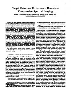
Figure 1. CO-BISTCM: (a) System Model. (b) Transmitter and Receiver Structure.
[1] makes the system robust by providing both space and time diversity for a given hamming distance of the convolutional code [27]. The bit-wise interleaving on the transmitter side improves the diversity order of the system. The performance of bit-interleaved space-time coded modulation (BI-STCM) with iterative decoding is analyzed for MIMO channels [28]. Here in this paper, we extend the concept of virtual MIMO (i.e cooperative networks) with modified space time coding and analyze a cooperative system with the serial concatenated bit-interleaved space-time coded modulation (BI-STCM). We discuss the Alamouti and orthogonal space-time block coded cooperative (OSTBC-CO) two stage transmission protocol for two relay network. Both amplify-and-forward and decode-and-forward techniques are considered for the relaying of partner’s user information. The channel coefficients are modeled as Nakagamim distribution. The Rayleigh distribution is obtained at m = 1 and m = ∞ makes the channel non-fading i.e. AWGN. Similarly Nakagami-n (Rice) and Nakagami-q (Hoyt) distributions can be obtained [30]. The system is analyzed using M -PSK modulation scheme. Same Errorfree feedback bound (EF-bound) approach is followed as given in [29]. The performance parameters analyzed here include symbol-error rate, outage probability, capacity and cooperation gain. The main contribution of this paper is the derived closed-form expression for the MGF of metric difference for STC-CO and OSTBC-CO transmission protocols and the use of MGF based approach to analyze the BER performance. Finally, simulation results are presented to validate the theoretical results. The remainder of this paper is organized as follows. Section II describes the CO-BISTCM system model, transmitter and receiver structure. Section III explains the STC-CO protocol. Section IV presents the OSTBC-CO protocol, its input-output equations and signal-to-noise ratio. The BER bounds are given in section V. The closedform expressions of the MGF for STC-CO and OSTBCCO transmission protocols are derived in section VI. The numerical and simulation results are discussed in section VII. Finally, the conclusions are given in section VIII. © 2010 ACADEMY PUBLISHER
Notation. The E(.), Γ(.), and |.| denote the expectation operator, the gamma function and the magnitude of complex value respectively. Tx → Ty describes the link between terminal x and y. II. CO-BISTCM S YSTEM M ODEL We consider a multiple-terminal network as shown in the Figure 1 (a), where the terminals Tj (j = 1, · · · , N ) are the users (wireless device) and the terminal Td is a destination (base station). The terminals Tj cooperate with each other to send their information to the destination Td and all the terminals are equipped with a single antenna. The CO-BISTCM transmitter and receiver are installed in the transmitting terminals (Tj ) and destination (Td ), respectively. A. CO-BISTCM Transmitter and Receiver Figure 1 (b) illustrates the CO-BISTCM transmitter and receiver. The kc information bits are first encoded by a nonrecursive convolutional encoder of rate R = nkcc . The codeword c is then interleaved by trow × tcol block interleaver to generate a codeword of L blocks, each with length of qµ bits. Space-time mapper is used to map each block onto q symbols from an M -ary complex signal constellation (M = 2µ ) , using space-time cooperation protocol (explained in next section). The average symbol energy, Exy = µEb , where Eb is the energy per information bit. CO-BISTCM receiver at the destination is shown in the Fig. 1 (b). The maximal ratio combiner (MRC) is used to combine the signals through different paths and then noise is normalized at the receiver of destination. The hard decision of the information bits is made from the soft information. The extrinsic logarithmic likelihood ratios (LLRs) are generated by the de-mapper. The LLRs are then de-interleaved and then they are fed to the SISO a-posteriori decoder. The iterative decoding is performed by giving the posterior probability (MAP) as a feedback through the interleaver to de-mapper for the next iteration. The 8-PSK constellation is translated into binary channel
JOURNAL OF COMMUNICATIONS, VOL. 5, NO. 4, APRIL 2010
299
from the four possible pairs by the two bits that are fed back to demapper through interleaver at the 2ndpass decoding [25]. In this regard, Set partitioning (SP) labeling outperforms Gray labeling for iterative decoding [25]. B. Channel The CO-BISTCM system operates over independent and identical (i.i.d.) versatile Nakagami-m fading channels. The Rayleigh distribution is obtained at m = 1 and m = ∞ makes the channel non-fading i.e. AWGN. For Ricean distribution m = (K + 1)2 /(2K + 1) [31] (where K is the Rice factor). All the channels are subject to block fading, where the channel coefficients are assumed to be same for the duration of four time slots and are considered to vary independently afterwards. It is assumed that all the users are transmitting signals through orthogonal channels by using TDMA, FDMA or CDMA schemes [7]. Perfect channel state information (CSI) is known to the receiver. The fading coefficient of link Tx → Ty is denoted as hxy and the probability density function (pdf) of |hxy | is given as [32] �m � 2|hxy |2m−1 m × f (|hxy |) = E(|hxy |2 ) Γ(m) � � −m|hxy |2 exp , (1) E(|hxy |2 ) where Γ(.) is a gamma function and E(|hxy |2 ) = 1. Let αxy = |hxy |2 is gamma distributed random variables and its pdf is given as f (αxy ) =
m−1 2mm αxy exp(−mαxy ). Γ(m)
(2)
III. S PACE -T IME C ODED C OOPERATION (STC-CO) P ROTOCOL This section describes the frame structure, transmission signaling and input-output equations for STC-CO protocol for two-user cooperation scenario. A. STC-CO Channel Allocation The time and frequency devision channel allocation is given in Figure 2, where each transmitting terminal is allocated a different frequency (f1 , f2 , · · · , fN ) and two time frames are allocated for the transmission of its own information bits to partner terminal and destination terminal known as listening sub-frame. Only one time frame is allocated to forward the partner’s message to the destination and it is known as cooperation sub-frame. B. STC-CO Signaling The Alamouti code is given as [1] � � x1 x2 C= −x∗2 x∗1 We focus on the message sent by the source terminal Ts to the destination terminal Td through a direct path © 2010 ACADEMY PUBLISHER
Figure 2. STC-CO Channel Allocation. TABLE I. STC-CO T RANSMISSION P ROTOCOL
Time Slot 1 Ts → Tr x1 → ysr1
Time Slot 2 Ts , Tr → Td x2 → ysd2 xr2 → yrd2
Time Slot 3 Ts → Tr −x∗2 → ysr2
Time Slot 4 Ts , Tr → Td x∗1 → ysd4 xr4 → yrd4
and a relay terminal (Tr ), where s, r ∈ {1, · · · , N }. The signaling in STC-CO protocol is explained in a Table II. In first time slot, the source terminal Ts sends a symbol x1 to the relay terminal Tr . In second time slot the Ts transmits x2 and Tr retransmits the signal received in first time slot to the destination terminal Td . In case of amplify-and-forward (AF), the Tr will first amplify and then retransmits the signal received from the Ts in first time slot. In decode-and-forward (DF), only the signal that is successfully decoded by Tr , will be forwarded to Td [34]. Here we assume the Ts to Td and Tr to Td links to be orthogonal. In third time slot Ts sends the symbol −x∗2 to Tr . The Tr retransmits the received signal using AF or DF scheme and Ts transmits x∗1 to Td in fourth time slot. C. Input-Output Equations This section presents the input-output equations for the two-user CO-BISTCM system using the ST-CO protocol. In first time slot the signal received at the Tr is given as p ysr1 = Esr hsr x1 + nsr1 , (3) where nr ∼ CN (0, N0 ), denotes Additive White Gaussian Noise (AWGN) at Tr . We consider the following two schemes for the Tr : A) amplify-and-forward and B) decode-and-forward For AF: In AF scheme, the signal received at Tr is normalized and retransmited to Td . In second time slot, the received signal x1 through Tr at Td can be written as r Esr Erd yrd2 = hsr hrd x1 + n ˜ rd2 , (4) Esr + N0 ˜0 ) and where �n ˜ rd2 ∼ CN (0, N � Erd 2 ˜ N0 = Esr +1 |hrd | + 1 N0 .
300
JOURNAL OF COMMUNICATIONS, VOL. 5, NO. 4, APRIL 2010
TABLE II. OSTBC-CO T RANSMISSION P ROTOCOL
Time Slots 1, 2 Ts → Tri x1 → ysr1 1 x2 → ysr2 2
Time Slot 3 Ts , Tri → Td x3 → ysd3 xr1 3 → yr1 d3 xr2 3 → yr2 d3
Time Slots 4, 5 Ts → Tri −x∗2 → ysr1 4 x∗1 → ysr2 5
Time Slot 6 Ts , Tri → Td xr1 6 → yr1 d6 xr2 6 → yr2 d6
After noise normalization (4) can be written as r 1 Esr Erd yrd2 = hsr hrd x1 + nrd2 , ω Esr + N0
(5)
where nsd2 ∼ CN (0, N0 ). Similarly in the fourth time slot, the received signals at the destination from the Tr and Ts can be written as r 1 Esr Erd yrd4 = − hsr hrd x∗2 + nrd4 , (7) ω Esr + N0 p (8) Esd hsd x∗1 + nsd4 , ysd4 = where n ˜ ri d4 ∼ CN (0, N0 ). The received signals during four time slots at Td can be written in matrix form as (9)
where YT
yrd2
= �
ysd2
HT
=
A 0 0 B
XT ´T N
=
x1
= q
nrd2
x2
B∗ 0 �
∗ yrd4
0 −A∗
∗ ysd4 �
� 1×4
Time Slot 12 Ts , Tri → Td −x∗2 → ysd12 xr2 12 → yr2 d12
The equivalent SNR at the destination for STC-CO protocol can be expressed as: For AF: γST C−CO =
|A|2 +|B|2 N0
! =
1 N0
1 Esr Erd ω 2 Esr +N0 αsr αrd
+ Esd αsd (14)
For DF: γST C−CO
= =
|C|2 + |B|2 N0 1 (Erd αrd + Esd αsd ) N0
(15)
IV. O RTHOGONAL S PACE -T IME C ODED C OOPERATION (OSTBC-CO) P ROTOCOL This section describes the transmission signaling and input-output equations for OSTBC-CO protocol of COBISTCM system. A. OSTBC-CO Channel Allocation
n∗rd4
n∗sd4
� 1×4
√ rd Esr and A = ω1 EEsr Esd hsd . Multi+N0 hsr hrd and B = ply HH on both side of (9) as � � � x1 ´ (10) + HH N, HH Y = |A|2 + |B|2 x2 � � y1 H where H Y = . y2 For DF: In DF, the Tr when it decodes the signal received from Ts successfully, forwards it to Td in second time slot [34]. The signal received from Tr at Td in second and fourth time slots are given as p yrd2 = Erd hrd x1 + nrd2 , (11) p yrd4 = − Erd hrd x∗2 + nrd4 . (12) For DF, the received signals at the destination in matrix form and equivalent SISO model are given as � � � � � x1 y1 2 2 ´ (13) + HH N, = |C| + |B| x2 y2 √ where C = Erd hrd . © 2010 ACADEMY PUBLISHER
Time Slot 10,11 Ts → Tri x∗3 → ysr2 11
2×4
1×2
nsd2
Time Slot 9 Ts , Tri → Td −x∗1 → ysd9 xr1 9 → yr1 d9
D. Equivalent Signal-to-Noise Ratio (SNR)
rd |hrd |2 + 1 and nrd2 ∼ CN (0, N0 ) where ω 2 = EsrE+N 0 The signal x2 received at Td from Ts through direct path in second time slot can be written as p ysd2 = Esd hsd x2 + nsd2 , (6)
´ Y = HX + N,
Time Slot 7,8 Ts → Tri x∗3 → ysr1 7
The time and frequency devision channel allocation is given in Figure 3, where each transmitting terminal is allocated a different frequency (f1 , f2 , · · · , fN ) and three time frames (listening sub-frames) are allocated for the transmission of its own information to two partner terminals and a destination. Two time frames (cooperation sub-frames) are allocated to forward the message of other two partner terminals to the destination.
Figure 3. OSTBC-CO Channel Allocation.
JOURNAL OF COMMUNICATIONS, VOL. 5, NO. 4, APRIL 2010
YT
yr1 d3
=
HT XT ´T N
A1 = 0 0 =
x1
=
nr1 d3
ysd3
yr∗1 d6
yr∗2 d6
0 A∗2 0 0 B 0 �
0 −A∗1 0
−B ∗ 0 0
yr2 d3 0 A2 0
x2
x3
nr2 d3
nsd3
n∗r1 d6
0 0 A∗1
∗ ysd9
0 −B ∗ 0
yr2 d12
ysd12
� 1×9
0 0 A∗2 3×9
n∗r2 d6
n∗r1 d9
n∗sd9
nr2 d12
nsd12
� 1×9
(20)
E
In orthogonal transmission, the number of time slots increases with the increase of transmitted symbols. The general form of OSTBC is given as [33] x1 (1) x2 (1) . . . xN (1) x1 (2) x2 (2) . . . xN (2) C= .. .. .. .. . . . . x2 (t)
yr∗1 d9
1×3
B. OSTBC-CO Signaling
x1 (t)
301
...
xN (t)
id where ωi2 = Esr r+N |hri d |2 +1, nri d3 ∼ CN (0, N0 ) and 0 i nsd3 ∼ CN (0, N0 ). Similarly the signals received at Td in sixth, ninth and twelve time slots are given as
yr1 d6
=
yr2 d6
=
yr1 d9
=
ysd9
=
yr2 d12
=
ysd12
=
t×N
where t is the number of time slots used by N number of transmit antennas. For simplicity, we assume 4 × 3 OSTBC by considering three-user cooperation scenario. x1 x2 x3 −x∗2 x∗1 0 C= x∗3 0 −x∗1 0 x∗3 −x∗2 4×3 The signaling in OSTBC-CO protocol is explained in Table II. In first and second time slots, the Ts transmits signal x1 to Tr1 and x2 to relay Tr2 , respectively. In third time slot, Tr1 and Tr2 retransmit the signal using AF or DF mode to the destination Td and Ts transmits signal x3 to Td . In fourth and fifth time slots, Ts transmits −x∗2 to Tr1 and x∗1 to Tr2 respectively. In sixth time slot, Tr1 and Tr2 forward the scaled signals to Td . Similarly, seventh, eight and ninth time slots, x∗3 and −x∗1 is transmitted to Td through Tr1 and direct path, respectively. In tenth, eleventh and twelve time slot, signal x∗3 and −x∗2 are transmitted through Tr2 and direct path, respectively.
s −1 Esr1 Er1 d hsr hr d x∗ + nr1 d6 , ω1 Esr1 + N0 1 1 2 s 1 Esr2 Er2 d hsr hr d x∗ + nr2 d6 , ω2 Esr2 + N0 2 2 1 s 1 Esr1 Er1 d hsr hr d x∗ + nr1 d9 , ω1 Esr1 + N0 1 1 3 p − Esd hsd x∗1 + nsd9 , s 1 Esr2 Er2 d hsr hr d x∗ + nr2 d12 , ω2 Esr2 + N0 2 2 3 p − Esd hsd x∗2 + nsd12 . (18)
The above equations can be written in matrix form as ´ Y = HX + N,
(19)
´ where in (20). and Ai = q Y, H, X and N are given √ Eri d Esri 1 Esd hsd . MRC is perωi Esri +N0 hsri hri d , B = formed at the Td . The equivalent SISO model is obtained by pre-multiplying with HH both sides of (19).
y1 y2 = y3
! x 1 ´ (21) |Ai |2 + |B|2 x2 + HH N. i=1 x3
2 X
C. Input-Output Equations Using the OSTBC-CO protocol for the multiple-user CO-BISTCM system, the received signal at the Ti (i = 1, 2) in i-th time slot is given as p ysri = Esri hsri xi + nri . (16) where nri ∼ CN (0, N0 ). For AF: In AF scheme, the destination receives the signal xi through Ti and x3 from the Ts through direct path. The received signal in third time slot can be written as s 1 Esri Eri d yri d3 = hsr hr d xi + nri d3 , ωi Esri + N0 i i p ysd3 = Esd hsd x3 + nsd3 . (17) © 2010 ACADEMY PUBLISHER
For DF: In DF, the received signals at destination in four time slots (i.e. 3, 6, 9 and 12) are given as yri d3
=
ysd3 yr1 d6
= =
yr2 d6
=
yr1 d9
=
ysd9 yr2 d12
= =
ysd12
=
p Er d hr d xi + nri d3 , p i i E h x +n , psd sd 3 ∗ sd3 − Er1 d hr1 d x2 + nd6 , p Er d hr d x∗ + nr2 d6 , p 2 2 1∗ Er d hr d x + nd9 , p1 1 3 − Esd hsd x∗1 + nsd9 , p Er d hr d x∗ + nd12 , p2 2 3 − Esd hsd x∗2 + nsd12 . (22)
302
JOURNAL OF COMMUNICATIONS, VOL. 5, NO. 4, APRIL 2010
Φ∆(x,z)|αrd (s)
1
=
Φ∆(x,z) (s)
1−
�m × � − 1)
1−
m
�m � sd2E αrd (2sN0 − 1)
(35)
1
=
1−
Esd 2 m sdE (2sN0
1 � − 1) 1 −
For DF, the received signals at the destination in matrix form and equivalent SISO model are given as ! x 2 y1 1 X ´ (23) y2 = |Ci |2 + |B|2 x2 + HH N, i=1 y3 x3 p √ where Ci = Eri d hri d and B = Esd hsd .
Erd 2 m sdE (2sN0
(36) (38)
��m − 1)
Φ∆( x,z) (s) is the Laplace transform (MGF) of the metric difference ∆(x, z) between x and z. The PEP for BICMID can be written as [26] Z α+j∞ ds 1 × [ψef (s)]d , (28) f (d, µ, χ) ≤ 2πj s α−j∞ where ψef (s) =
D. Equivalent Signal-to-Noise Ratio (SNR)
µ 1 1 XX X Φ∆(x,z) (s). µ2µ i=1 i
(29)
b=0 x∈χ
The equivalent SNR at the destination for OSTBC-CO protocol can be expressed as: For AF: P2 |Ai |2 +|B|2 γOST BC−CO = i=1 N0 ! P2 1 Esri Eri d 1 = N0 i=1 ω 2 Esr +N0 αsri αri d + Esd αsd i
1 Esr Erd Esr +N0 Erd Esr +N0 αrd +1
�m �m × 1 − Emsd sd2E (2sN0 − 1) 1 − Emsr sd2E (2sN0 − 1) ! m X m−υ 1+ Cυ (s)mm (ρ(s)) ψ(m, m − υ + 1, mρ(s)) υ=1
=
Φ∆(x,z) (s)
Esd 2 m sdE (2sN0
i
(24)
b
The union bound of probability of bit error for convolutional code of rate R = kc /nc is given as [24] Pb ≤
∞ 1 X W1 (d)f (d, µ, χ), kc
(30)
d=dH
where dH is the minimum Hamming distance of the convolutional code and W1 (d) is the total input weight of error events at d.
For DF: P2 γOST BC−CO
= =
|Ci |2 + |B|2 N0 ! 2 X Eri d αri d + Esd αsd
i=1
1 N0
i=1
(25)
VI. M OMENT G ENERATING F UNCTION (MGF) OF M ETRIC D IFFERENCE In this section, we describe the metric difference and the MGF of that metric difference for CO-BISTCM system. The branch metric for i-th bit is given as [24] λi = mini {|y − hx|2 },
(31)
x∈χb
V. B IT E RROR R ATE (BER) B OUND The probability of decoding a received sequence as a codeword x with an error weight d (hamming distance) given that the transmitted codeword is z is known as pairwise error probability (PEP). The PEP union bound for BICM can also be expressed in the form of moment generating function (MGF) approach, given as [24] Z α+j∞ ds 1 × [ψub (s)]d , (26) f (d, µ, χ) ≤ 2πj s α−j∞
where χib denotes the subset of all the symbols in the constellation having value b ∈ {0, 1} at i-th position. The metric difference between x and z can be denoted as
where d is hamming distance of convolutional code and
The conditional MGF expression can be obtained as � � Φ∆(x,z) (s) = E exp −sd2E (|A|2 + 2|B|2 )(1 − 2sN0 ) , (34) where d2E = |x − z|2 is a squared Euclidean distance.
ψub (s) =
µ 1 1 XX X X Φ∆(x,z) (s). µ2µ i=1 i i b=0 x∈χ z∈χ¯ b b
© 2010 ACADEMY PUBLISHER
(27)
∆(x, z) = |y − hx|2 − |y − hz|2 . The MGF of ∆(x, z) can be expressed as n o Φ∆(x,z) (s) = E e−s∆(x,z) .
(32)
(33)
JOURNAL OF COMMUNICATIONS, VOL. 5, NO. 4, APRIL 2010
A. MGF of STC-CO Protocol For AF: After substituting the values of A and B in (34), the MGF given αrd by taking the average with respect to αsd and αsr , we get the expression in (35). After some simple mathematical steps, we obtain closedform expression of MGF as (36), where ψ(.; .; .) is the confluent hypergeometric function of second kind [35]. ξ(αri d ) and Cυ (s) along with the detailed derivation are given in Appendix I. For DF: The conditional MGF for DF scheme is obtained by substituting A and B in (34) and can be written as n o 2 Φ (s) = E e(−sdE (1−2sN0 )(Erd αrd +2Esd αsd )) .
303
mapped 8-PSK modulation. The iterative decoding helps in converging the BER curves to the theoretical bound. In Figure 4, the BER curves converge to the EF bound at the 4-th iteration. The error floor effect occurs at BER less than 10−4 . The derived theoretical expression can be used to predict the system performance at medium and high SNR, where the bound is tight. 0
10
−1
10
−2
10
∆(x,z)
(37)
−3
10 BER
The unconditional MGF can be written as (38).
−4
10
B. MGF of OSTBC-CO Protocol For AF: On substituting the values of Ai (i = 1, 2) and B in (34) and taking the average with respect to αsd and αsri , we get the expression in (39). After some simple mathematical steps, (39) can be written as (40). ξ(αri d ) and Cυ (s) along with the detailed derivation are given in Appendix II. For DF: Similarly, the unconditional MGF for DF scheme can be written as (41). VII. R ESULTS AND D ISCUSSION In this section, we verify the analytical expressions obtained by presenting the Monte-Carlo simulation results. The comparison of STC-CO and OSTBC-CO protocols for various m values are also shown. The analytical results of EF bounds (36) and (40) are evaluated using Mathamatica and simulation results are obtained using Matlab environment by simulating 107 information bits. The 1/2 convolutional encoder of generator sequences g = [133 171]8 and a random interleaver are used on the transmitter side. The mapper assigns the interleaved codewords into M constellation points using M -PSK modulation scheme. The set partitioning (SP) labeling map for 8-PSK modulation [25] is used in the simulation. The space time encoder generates the Alamouti and space-time block codes for STC-CO and OSTBC transmission protocols, respectively. The simulation results are obtained for independent and identical (i.i.d.) Rayleigh (m = 1) and Nakagami block fading channels . On the receiver side, the SISO decoder using the logMAP algorithm with iteration for decoding is modeled to estimate the transmitted signal. The analysis is performed by evaluating the BER and achievable rates for the system over uncorrelated Rayleigh (m = 1) and Nakagami block fading channels. Figure 4 shows simulation results with analytical error free feedback (EF) bounds (36) versus average signal-tonoise ratio of STC-CO protocol for Nakagami-2 fading channels. It shows the BER curves of the single-relay CO-BISTCM system operating in AF mode. These curves are simulated upto 5 iterations using set-partitioning (SP) © 2010 ACADEMY PUBLISHER
−5
10
−6
10
−7
10
0
Iteration=1 Iteration=2 Iteration=3 Iteration=4 Iteration=5 EF Bound 0.5
1
1.5
2
2.5 SNR (dB)
3
3.5
4
4.5
5
Figure 4. BER curves of STC-CO protocol over Nakagami-2 fading channels, 8-PSK and SP labeling.
Figure 5 shows the EF bound and the simulation results for the OSTBC-CO transmission protocol over Nakagami2 fading channels for five number of iterations on the decoder side. The BER curves converge at SNR 1.5dB in 4-th iteration. In this case, the error floor occurs at SNR less than 10−4 , similar to the previous case. It is clear from both figures 4 and 5 that OSTBC-CO converge to the EF Bound 1dB earlier than that for STC-CO. Figure 6 presents the EF bound and the simulation results for the same system but over Rayleigh fading channels (m = 1). Here the BER curves converge to the theoretical bound at 2dB SNR value, whereas, in the case of m = 2 (Figure 5) the BER curves converge at 1.5dB. Figure 7 shows the BER performance of STC-CO and OSTBC-CO protocols for 8-PSK SP signaling with m = 1 and m = 3 for single iteration at the decoder. It is clear from the results that performance gap between the two protocols increases as the SNR increases. Figure 8 shows the BER performance versus transmit SNR of STC-CO for the DF case with m = 1, 2, 3. VIII. C ONCLUSION We analyze the performance of BICM-ID based cooperative network over Nakagami-m and Rayleigh (m = 1) fading channels. We derive the closed-form MGF of the proposed system for both STC-CO and OSTBCCO transmission protocols. The BER theoretical bounds are obtained using MGF-based approach to predict the performance of the proposed system. The analysis is carried out for the M -PSK modulation scheme. It is
304
JOURNAL OF COMMUNICATIONS, VOL. 5, NO. 4, APRIL 2010
Φ∆(x,z)|αri d (s)
2 Y
1
=
�m 1 − Emsd sd2E (2sN0 − 1)
1
i=1
1 −
�
m
Φ∆(x,z) (s)
Φ∆(x,z) (s)
Er d i Esr +N0 i
αri d +1
(39)
� sd2E αri d (2sN0 − 1)
1
�m �2m × 1 − Emsd sd2E (2sN0 − 1) 1 − Emsr sd2E (2sN0 − 1) !2 m X m−υ 1+ Cυ (s)mm (ρ(s)) ψ(m, m − υ + 1, mρ(s)) υ=1
=
= 1−
Esd 2 m sdE (2sN0
1 � − 1) 1 −
Erd 2 m sdE (2sN0
0
(40) (41)
��2m − 1)
0
10
10
−1
−1
10
10
−2
−2
10
10
−3
−3
10
BER
BER
10
−4
−4
10
−5
10
−6
10
−7
10
m
Esr Er d i i Esr +N0 i
0
10
Iteration=1 Iteration=2 Iteration=3 Iteration=4 Iteration=5 EF Bound
−5
10
Iteration=1 Iteration=2 Iteration=3 Iteration=4 Iteration=5 EF Bound
−6
10
−7
0.5
1
1.5
2
2.5
3
3.5
10
0
0.5
1
1.5
SNR (dB)
Figure 5. BER curves of OSTBC-CO protocol over Nakagami-2 fading channels, 8-PSK and SP labeling.
clear from simulation results that a significant gain is achieved in the performance of the system due to the space and code diversities by introducing the space-time coded cooperation and bit-interleaved coded modulation with iterative decoding. We observe that the performance of OSTBC-CO is better than that of STC-CO transmission protocol. In general, the proposed system achieves better performance. The results show that the derived expression can be used to predict the performance of the proposed system for medium and higher SNR where the simulation results converge to the EF bound. The results obtained in this paper can be extended to other fading channel models. A PPENDIX I D ERIVATION OF (36) After substituting the values of A and B in (34), we obtain conditional MGF as (42). After taking average of (42) with respect to αsd and αsr , we obtain an expression in (35). After some simple mathematical steps, (35) can be m−1 c αrd +···+c1 αrd +c0 written as (43). Where ξ(αrd ) = m−1 (α m rd +ρ(s)) with ρ(s) =
Esr +N0 Erd Esr 1− m sd2E (2sN0 −1)
© 2010 ACADEMY PUBLISHER
and cm−1 , · · · , c1 , c0
2 SNR (dB)
2.5
3
3.5
4
Figure 6. BER curves of OSTBC-CO protocol over Rayleigh fading channels (m = 1), 8-PSK and SP labeling.
are real constants. After taking partial fraction of (43), we obtain (44). Where Cυ (s) = m dm−υ 1 ((α + ρ(s)) ξ(α )) | . By rd rd αrd =−ρ(s) (m−υ)! dαm−υ rd taking average of (44), we obtain closed-form expression of MGF as given in (36).
A PPENDIX II D ERIVATION OF (40) By substituting the values of Ai and B in (34), we obtain conditional MGF as (45). The MGF given αri d by taking average of (45) with respect to αsd and αsri , we get an expression as (39). After some simple mathematical steps, (39) can be written as (46). Where ξ(αri d ) =
cm−1 αm−1 +···+c1 αri d +c0 r d
i . After taking m (αri d +ρ(s)) partial fraction of (46), we obtain (47). Where Cυ (s) = m dm−υ 1 (m−υ)! dαm−υ ((αri d + ρ(s)) ξ(αri d )) |αri d =−ρ(s) . By ri d
taking average of (47), we obtain closed-form expression of MGF as given in (40).
JOURNAL OF COMMUNICATIONS, VOL. 5, NO. 4, APRIL 2010
305
( Φ∆(x,z) (s)
= E
!!)
Esr Erd Esr +N0
exp −sd2E (1 − 2sN0 )
Erd Esr +N0 αrd
1 �m − 1) 1−
+1
αsr αrd + 2Esd αsd
(42)
(43) �m × (1 + ξ(αrd )) − 1) ! m X Cυ (s) 1 Φ∆(x,z)|αrd (s) = (44) �m �m × 1 + (αrd + ρ(s))υ 1 − Emsr sd2E (2sN0 − 1) 1 − Emsd sd2E (2sN0 − 1) υ=1 Esri Eri d 2 X E +N sr 0 i α + E α (45) α Φ∆(x,z) (s) = E exp −sd2E (1 − 2sN0 ) r d sd sd sr i i Eri d i=1 Esr +N0 αri d + 1
Φ∆(x,z)|αrd (s)
=
1−
Esd 2 m sdE (2sN0
Esr 2 m sdE (2sN0
i
Φ∆(x,z)|αri d (s) Φ∆(x,z)|αrd (s)
=
2 Y
1 �m 1− 1 − Emsd sd2E (2sN0 − 1)
�2m Esr 2 m sdE (2sN0 − 1)
1
= 1−
Esd 2 m sdE (2sN0
�m − 1) 1−
Esr 2 m sdE (2sN0
0
�2m − 1)
i=1 2 Y i=1
(1 + ξ(αri d ))
(46)
! Cυ (s) (47) 1+ (αri d + ρ(s))υ υ=1 m X
0
10
10
m=1 m=2 m=3
Iteration 1 −1
10 −1
BER
BER
10
−2
Iteration 2
10
−2
10
−3
10
m=1 m=3 STC−CO OSTBC−CO
−3
10
0
0.5
−4
1
1.5
2 SNR (dB)
2.5
3
3.5
4
10
0
0.5
1
1.5
2
2.5 SNR (dB)
3
3.5
4
4.5
5
Figure 7. BER comparison of STC-CO and OSTBC-CO protocols for AF case with m = 1, 3 and µ = 3.
Figure 8. BER variation using STC-CO protocol for DF case over Nakagami-m fading channels (m = 1, 2, 3).
ACKNOWLEDGMENT
[5] M. Janani,A. Hedayat, T. E. Hunter and A. Nosratinia, “Coded cooperation in wireless communications: Spacetime transmission and iterative decoding,” IEEE Trans. Signal Process., vol. 52, pp. 362-372, Feb. 2004. [6] V. Genc, S. Murphy, Y. Yu, and J. Murphy, “Ieee 802.16j relay-based wireless access networks: an overview [recent advances and evolution of WLAN and WMAN standards],” IEEE Wireless Commun. Mag., vol.15, pp.56-63, 2008. [7] J. N. Laneman,D. N. C. Tse, and G. W. Wornell, “Cooperative diversity in wireless networks: low-complexity protocol and outage behavior,” IEEE Trans. Inform. Theory, vol. 50, no. 12, pp. 3062-3080, Dec. 2004. [8] J. N. Laneman, and G. W. Wornell, “Distributed spacetime-coded protocols for exploiting cooperative diversity in wireless networks,” IEEE Trans. Inf. Theory, vol.49, no.10, pp.2415-2425, Oct. 2003. [9] A. Sendonaris,E. Erkip, and B. Aazhang, “User cooperation diversity-Part I: System description,” IEEE Trans. Commun., vol.51, no.11, pp.1927-1938, Nov. 2003. [10] A. Sendonaris,E. Erkip, and B. Aazhang, “User cooperation diversity-Part II: Implementation aspects and per-
The first and second authors would like to thank NWFP University of Engineering and Technology, Peshawar, Pakistan and Higher Education Commission, Pakistan, for providing funds for their higher studies abroad. R EFERENCES [1] S. M. Alamouti, “A simple transmit diversity technique for wireless communications,” IEEE J. Select. Areas Commun., vol. 16, no. 8, pp. 1451-1458, Oct. 1998. [2] V. Kuhn, Wireless Communications over MIMO channels. John Wiley, 2006. [3] A. Nosratinia,T. E. Hunter, and A. Hedayat, “Cooperative communication in wireless networks,” IEEE Commun. Magzine, vol. 256, pp. 74-80, Oct. 2004. [4] T. E. Hunter, and A. Nosratinia, “Diversity through coded cooperation,” Proc. of IEEE International Symposium on Information Theory, vol. 220, 2002.
© 2010 ACADEMY PUBLISHER
306
formance analysis,” IEEE Trans. Commun., vol.51, no.11, pp.1939-1948, Nov. 2003. [11] P. A. Anghel,G. Leus, and M. Kaveh, “Multi-user spacetime coding in cooperative networks,” Proc. of IEEE International Conference on Acoustics, Speech, and Signal Processing,(ICASSP ’03), vol. 4, pp. 73-76, Apr. 2003. [12] S. Atapattu and N. Rajatheva, “Analysis of Alamouti code transmission over TDMA-based cooperative protocol,” IEEE 67th Vehicular Technology Conference, VTC2008, Singapore, Spring 2008. [13] M. O. Hasna, and M.-S. Alouini, “Outage probability of multipath transmission over Nakagami fading channels,” IEEE Commun. Letter, vol. 7, no. 5, pp. 216-218, May 2003. [14] R. U. Nabar, H. Bolckei, and F. W. Kneubuhler, “Fading relay channels performance limits and space-time signal design,” IEEE J. Select. Areas Commun., vol. 22, no. 6, pp. 1099-1109, Aug. 2004. [15] G. K. Karagiannidis, T. A. Tsiftsis, and R. K. Mallik, “Bounds for multihop relayed communications in Nakagami-m fading,” IEEE Trans. Commun., vol. 54, no. 1, pp. 18-22, Jan. 2006. [16] S. Ikki, and M. H. Ahmed, “Performance analysis of cooperative diversity wireless networks over Nakagami-m fading channels,” IEEE Commun. Lett., vol. 11, no. 4, pp. 334-336, Apr. 2007. [17] Z. Fang, L. Li, and Z. Wang, “Asymptotic performance analysis of multihop relayed transmission over Nakagamim fading channels,” IEICE Commun. Letter, vol. E91-B, no. 12, pp. 4081-4084, Dec. 2008. [18] L.-L Yang and H.-H. Chen, “Error probability of digital communications using relay diversity over Nakagami-m fading channels,” IEEE Trans. Wireless Commun., vol. 7, no. 5, pp. 1806-1811, May 2008. [19] H. Shin and J. B. Song, “MRC analysis of cooperative diversity with fixed-gain relays in Nakagami-m fading channels,” IEEE Trans. Wireless Commun., vol. 7, no. 6, pp. 2069-2074, June 2008. [20] I. Khan, S. A. K. Tanoli, and N. Rajatheva, “SER analysis of hybrid FDMA-TDMA based user cooperation diversity over Nakagami fading channels,” The 12th International Symposium on Wireless Personal Multimedia Communications (WPMC09), Sept. 2009. [21] A. Stefanov, and E. Erkip, “Cooperative coding for wireless networks,” IEEE Trans. Commun., vol. 52, pp. 1470-1476, May 2004. [22] P. Razaghi, M. Aleksic, and W. Yu, “Bit-Interleaved Coded Modulation for the Relay Channel Using Bilayer LDPC Codes,” 10th Canadian Workshop on Info. Theory, 2007. [23] E. Zehavi, “8-PSK trellis codes for a Rayleigh fading channel,” IEEE Trans. Commun., vol. 40, pp. 873-883, May 1992. [24] G. Caire, G. Taricco, and E. Biglieri, “Bit-interleaved coded modulation,” IEEE Trans. on Inform. Theo., vol. 44, no. 3, May 1998. [25] X. Li, and J. A. Ritcey, “Trellis-Coded Modulation with Bit Interleaving and Iterative Decoding,” IEEE J. on Select. Areas in Commun., vol. 17, no. 4, Apr. 1999. [26] X. Li, A. Chindapol, and J. A. Ritcey, “Bit-Interleaved coded modulation with iterative decoding and 8PSK signaling,” IEEE Trans. on Commun., vol. 50, no. 8, pp. 12501257, Aug. 2002. [27] Z. Hong, and B. L. Hughes, “Bit-interleaved space-time coded modulation with iterative decoding,” IEEE Trans. Wireless Commun., vol. 3, no. 6, pp. 1912-1917, Nov. 2004. [28] Y. Huang, and J. A. Ritcey, “Optimal constellation labeling for iteratively decoded bit-interleaved space-time coded modulation,” IEEE Trans. Inform. Theory, vol. 51, no. 5, pp. 1865-1871, May 2005. [29] A. Chindapol, and J. A. Ritcey, “Design analysis and performance evaluation for BICM-ID with square QAM
© 2010 ACADEMY PUBLISHER
JOURNAL OF COMMUNICATIONS, VOL. 5, NO. 4, APRIL 2010
constellations in Rayleigh fading channels,” IEEE J. Select. Areas Commun., vol. 19, no. 5, pp. 944-957, May 2001. [30] M. K. Simon, and M. S. Alouini, Digital Communication Over Fading Channels. New York: Wiley-Intersci., 2000. [31] R. Hasanizadeh, and S. Zokaei, “Optimal power allocation to diversity branches of cooperative MISO sensor networks,” Intl. J. of Sig. Proc., IJSP, Vol. 3, No. 4, pp 281-288, 2006. [32] M. Nakagami, The m-distribution as general formula for intensity distribution of rapid fading, in Statistical Methods in Radio Wave Propagation, 1960. [33] V. Tarokh, H. Jafarkhani, and A. R. Calderbank, “Spacetime block codes from orthogonal designs,” IEEE Trans. Inform. Theory, Vol. 45, pp 1456-1469, July 1999. [34] K. J. R. Liu, and A. K. Sadek, Cooperative Communications and Networking, Cambridge University Press, 2009. [35] I. S. Gradshteyn and I. M. Ryzhik, Table of Integrals, Series and Products 6th Ed. New York: Acad. Press, 2000. Imran Khan received his B.Sc. degree (Honors) in electrical engineering from NWFP University of Engineering and Technology, Peshawar, Pakistan in 2003 and M.Sc. in telecommunications engineering from the Asian Institute of Technology, Thailand, in 2007. He is currently working towards the PhD. degree at School of Engineering and Technology, Asian Institute of Technology, Thailand. Earlier he has been working as Lecturer at NWFP University of Engineering and Technology, Peshawar, Pakistan since 2004. He is student member of IEICE and IEEE. Mr. Khan’s research interests include performance analysis of wireless communications systems, OFDM, OFDMA, MIMO, BICM-ID based systems and cooperative networks Shujaat Ali Khan Tanoli received his B.Sc. degree in electrical engineering from COMSATS Institute of Information Technology, Pakistan in 2006 and M.Sc. in Telecommunications Engineering from the Asian Institute of Technology, Thailand, in 2009. He is currently working towards the PhD degree at the School of Engineering and Technology, Asian Institute of Technology, Thailand. He is student member of IEEE. Mr. Tanoli’s research interests include performance analysis of wireless communications systems, OFDMA, BICM-ID based systems and cooperative networks. Nandana Rajatheva received the B.Sc. degree in electronic and telecommunication engineering (with first class honors) from the University of Moratuwa, Moratuwa, Sri Lanka, and the M.Sc. and Ph.D. degrees from the University of Manitoba,Winnipeg, MB, Canada, in 1987, 1991, and 1995, respectively. Currently, he is an Associate Professor of telecommunications in the School of Engineering and Technology, Asian Institute of Technology, Pathumthani, Thailand. Earlier, he was with the University of Moratuwa, Sri Lanka, where he became a Professor of Electronic and Telecommunication Engineering in June 2003. From May 1996 to December 2001, he was with TC-SAT as an associate professor. He is an editor of International Journal of Vehicular Technology (Hindawi) and senior member of IEEE (since 2001), Comsoc and VTS. Dr. Rajatheva’s research interests include digital and mobile communications, cooperative diversity, relay systems, OFDMA resource allocation, cognitive radio: detection/estimation techniques, space time processing MIMO systems and distributed video coding (DVC).