FACTA UNIVERSITATIS Series: Automatic Control and Robotics Vol. 11, No 1, 2012, pp. 57 - 67
PERFORMANCE CHARACTERISTICS OF A THREE-PHASE SELF-EXCITED INDUCTION GENERATOR DRIVEN BY REGULATED CONSTANT SPEED TURBINE
UDC 621.333 681.53 Milan Radić1, Zoran Stajić1, Nenad Floranović2 1
University of Niš, Faculty of Electronic Engineering, Department of Energetics, Serbia 2 Research & Development Center "ALFATEC" d.o.o. Niš, Serbia Abstract. In this paper, theoretical background and the method for easy calculation of static performance characteristics of a three-phase self-excited induction generator under varying loading conditions have been presented. Symmetrical, three-phase load of resistive type, constant rotor speed and constant value of excitation capacitors have been considered. Calculated characteristics have been verified through experiment in laboratory, using three-phase squirrel-cage 1.5 kW induction machine. Good agreement between experimentally obtained results and calculated performance curves has been achieved. Key words: self-excited, induction generator, constant speed, turbine
1. INTRODUCTION In certain situations, when connection to the electrical grid is not available, induction generators can be still used for power generation, but have to be supplied with external source of reactive power. It is usually done by connecting a symmetrical capacitor bank in parallel with the stator of a generator. If the value of capacitance is properly chosen, along with rotational speed, an unloaded generator will be able to build up stable voltage on its terminals, thus becoming a self-excited induction generator (SEIG). This phenomenon has been identified almost one century ago, but during a long period of time it had become usual to consider SEIG as a specific mode of operation that was theoretically possible, but practically unacceptable, due to unstable voltage and frequency under loading conditions. Great mathematical difficulties that had follow any attempt to perform serious analysis of SEIG operation, made additional contribution to such negative opinion. For those reaReceived May 10, 2012 Corresponding author: Milan Radić University of Niš, Faculty of Electronic Engineering, Department of Energetics, Aleksandra Medvedeva 14, 18000 Nis, Serbia • E-mail:
[email protected] Acknowledgement: The paper is a part of the research done within the project III44006, supported by the Ministry of Education and Science of the Republic of Serbia.
58
M. RADIĆ, Z. STAJIĆ, N. FLORANOVIĆ
sons, for a long time small synchronous generators were favorite solutions for off-grid power generation. The previous way of thinking was abandoned when it became obvious that threephase squirrel-cage induction machine operated as a SEIG had many advantages compared to conventional synchronous generator. Low starting investments and maintenance costs, simplicity, robustness and extremely good behavior during short-circuits are just some of them [1]. Modern numerical-based methods for solving high-order nonlinear equations offer new, more sophisticated approach in the analysis of SEIG [12, 13]. In a few recent years, great advances in theoretical research [2, 3], [8, 9], [13, 14] and also towards practical improvements [4]-[7] in performance of a SEIG have been made. However, the proposed technical solutions are mostly based on intensive use of power electronics. It is still interesting to search for less complex methods, in order to overwhelm the weakness of voltage and frequency regulation in the future. This paper presents the results of theoretical and experimental research that was performed in order to identify the most important performance curves of the SEIG whose rotor is driven at constant speed. Such regulation is relatively simple and is basically exploited on hydro turbines driving synchronous machines. The main goal of our work was to develop a mathematical model capable of predicting deviations in voltage and frequency of a SEIG whose turbine is regulated in the described manner, while the load of a generator is changed. It has been assumed in analysis that symmetrical three-phase capacitor bank of constant per-phase capacitance is connected to the stator’s terminals. Also, it has been considered that SEIG is feeding symmetrical, but also variable, threephase resistive load. 2. CALCULATION OF PERFORMANCE CHARACTERISTICS The starting point in calculation of performance characteristics is the equivalent circuit of a SEIG. Compared to grid-connected operation mode, there are few significant differences, caused by the fact that voltage and frequency are not constant. Both of them are unknown variables whose values change, but depend on rotor speed, capacitance of excitation capacitors and loading conditions. In such circumstances, magnetizing inductance cannot be considered as constant, and standard equivalent circuit of an induction machine cannot be exploited. Suitable modification, shown in Fig 1. has to be used instead.
Fig. 1. Modified equivalent circuit for analysis of a three-phase SEIG
Performance Characteristics of a Three-Phase Self-Excited Induction Generator...
59
Symbols used in Fig. 1 have the following meaning: RL load resistance; Rs , X ls
stator resistance and leakage reactance;
Rr , X lr
rotor resistance and leakage reactance;
Rc , X m
magnetizing resistance and reactance;
XC
capacitor reactance;
U E (X m ) F F
stator voltage; normalized air-gap voltage; per-unit value of stator frequency; per-unit value of rotor speed.
All reactances in the modified equivalent circuit are given for machine’s rated frequency. Per-unit stator frequency F and per-unit rotor speed are expressed in terms of rated frequency of the machine and rated synchronous speed, respectively. It should be noticed that magnetizing reactance at rated frequency is considered as variable. This is important in order to take variation of magnetic flux saturation into account. Normalized air-gap voltage is represented as function dependant on actual value of Xm. Identification of this function can be performed by processing results obtained from ideal no-load test at rated frequency and several different voltages. When operating in stable steady state, SEIG can be treated as an oscillator with stator current of constant effective value. Total impedance seen by stator current I s is defined by:
Z tot Z s Z 1 Z 2 Z tot
Rs R jX C Rc Rr jX ls L jX L || jX lr || jX m || 2 F F F F F
(1) (2)
and has to be equal to zero, otherwise self-excitation will not exist. After some mathematical transformations, total impedance can be separated into real and imaginary part, which leads to the definition of the two basic equations of a SEIG: ReZ tot 0
(3)
ImZ tot 0 .
(4)
If all parameters of the equivalent circuit (except magnetizing reactance Xm) are known, and relative rotor speed is fixed (due to regulated turbine), the system defined by Eqs. (3) and (4) can be solved for any given value of load resistance RL. As it has been explained in [15], the pair of calculated roots (F, Xm), has to be real and has to fulfill the criterion: ( F 0) (0 X m X muns ) ,
(5)
where Xmuns is magnetizing reactance of unsaturated machine at rated frequency. Otherwise, self-excitation is not possible for the selected combination of values (RL, XC,).
60
M. RADIĆ, Z. STAJIĆ, N. FLORANOVIĆ
In order to obtain a numerical solution, it is necessary to use an iterative method, since Eqs. (3) and (4) are high-degree nonlinear equations. If any of the standard methods is selected for this purpose (e.g. Newton-Raphson iterative method), it will demand longlasting mathematical transformations in order to get appropriate form of equations [10, 11]. Even if this work is properly done, serious problems related to convergences of the iterative process may occur. In this paper, the system of two nonlinear Eqs. (3) and (4) is solved using the approach proposed by Haque in [13]. This approach is based on user-friendly numerical routine from MATLAB Optimization Toolbox, named fsolve, using nonlinear least-squares algorithm that employs Levenberg-Marquardt method. Unlike the standard iterative methods demanding long-lasting and fatiguing mathematical transformations, the proposed approach is very simple and fast. Also, it has extremely good convergence, and if no serious mistake is made during the definition of starting vector values, the roots of the system are easily calculated. When F and Xm are calculated, it is easy to solve equivalent circuit and to determine all other quantities that are of interest. From Fig. 1, it can be written: Is
E , F (Z 1 Z s )
(6)
Z 1E Z1 Z s
(7)
U and
PL
3U RL
2
.
(8)
Note that generated power PL has to be calculated regarding the original circuit in which resistive elements are not divided by F, since the modified equivalent circuit is valid only for calculation of voltages and currents. If parameters and XC are fixed (i.e. constant rotor speed and constant excitation capacitance conditions are considered), while load resistance RL is being varied in small steps using program loop, simultaneous calculations of stator voltage U, stator current IS and load power PL will result in identification of desired performance curves. In order to avoid problems related to convergency, it is good to start with the highest value of RL that is of interest. 3. EXPERIMENTAL VERIFICATION The explained theoretical approach is verified through the experiment performed in the laboratory, using three-phase squirrel cage, Y-connected induction machine as SEIG. The machine’s rated values for motor mode of operation are: 1.5 kW, 380 V, 50 Hz, 3.2 A, 2860 rpm. The parameters of the induction machine used in the experiment are given in Table 1.
Performance Characteristics of a Three-Phase Self-Excited Induction Generator...
61
Table 1. Machine parameters
Rs Rr Xls X ls
4.05 2.75 4.34
Xlr X lr
2.77
Xmuns X muns
226
Rc Rc
1200
Nonlinear function E / F = f (Xm) describing magnetic flux saturation for the test machine can be represented in a form of a third-degree polynomial function: E 348.1 2.34 X m 0.0156 X m2 0.00004861X m3 F
(9)
Graphic representation of this polynomial function, as well as experimental points obtained from no-load test at synchronous speed, can be found in [15]. Induction machine was mechanically coupled to the separately excited, regulated DC motor, which had the role of regulated hydro turbine. Regulation of speed has been performed by adjusting the armature voltage. Symmetrical, three-phase capacitor bank of constant per-phase capacitance C = 30 F was connected in parallel with stator of induction machine, in order to enable selfexcitation. The machine was loaded with symmetrical, three-phase, Y-connected resistive load with ability of discrete regulation. The experiment was performed for seven different operating points, and values of used load resistances RL are given in Table 2. For each experimental point, rotor speed was set to rated synchronous speed n = 3000 rpm, and then line stator voltage Ulin, stator frequency f, stator current Is and generated active power PL were measured. Table 2. Experimental points exp. RL []
1
2 517
3 309
4 205
5 104
6 69
7 52
4. EXPERIMENTAL RESULTS AND DISCUSSION Experimentally obtained results (except no-load points) are shown in Figs. 2-5, together with calculated performance curves.
62
M. RADIĆ, Z. STAJIĆ, N. FLORANOVIĆ 400
Line voltage on stator , Ulin [V]
350
C=30 F n=3000 rpm
300
calculated experimental
250 200 150 100 50 0
100
200
300
400
500
600
Load resistance per phase, R L []
Fig. 2. Line voltage U lin versus R L , for n 3000 rpm , C 30 F
54
Frequency , f [Hz]
52 50 48 46
calculated experimental
C=30 F n=3000 rpm
44 42 40 0
100
200
300
400
500
Load resistance per phase, R L [ ]
Fig. 3. Frequency f versus R L , for n 3000 rpm , C 30 F
600
Performance Characteristics of a Three-Phase Self-Excited Induction Generator...
63
3.0 2.8
Stator current, Is [A]
calculated experimental
C=30 F n=3000 rpm
2.6 2.4 2.2 2.0 1.8 1.6 1.4 1.2 1.0 0
100
200
300
400
500
600
Load resistance per phase, RL []
Fig. 4. Stator current I s versus R L , for n 3000 rpm , C 30 F
1400
Generated power , PL [W]
calculated experimental
C=30 F n=3000 rpm
1200 1000 800 600 400 200 0 0
100
200
300
400
500
Load resistance per phase, RL []
Fig. 5. Load power PL versus R L , for n 3000 rpm , C 30 F
600
64
M. RADIĆ, Z. STAJIĆ, N. FLORANOVIĆ
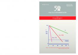
By observing Figs. 2-5, one can conclude that a fairly good agreement between experimentally measured values and calculated performance curves has been achieved, which proves the validity of the exploited calculation method. The best agreement between calculated and measured values can be noticed for stator current Is in Fig. 4, and also for stator line voltage Ulin (Fig. 2). The measured points for generated active power PL are somewhat lower than the predicted values, but the agreement can still be considered as acceptable (Fig. 5). The largest disagreement between the measured and calculated values can be noticed in Fig. 3, related to the stator frequency f. It is obvious that the actual measured values are always higher than the predicted curve on the whole studied range of load variation. Knowing that the active power transferred from the rotor to the stator via rotating magnetic field is proportional to the slip frequency, which is, at constant rotor speed, lower if stator frequency is higher, one can conclude that less active power than predicted is actually generated. This is in agreement with the results shown in Fig. 5. The explanation for the noticed disagreements could be found in the fact that, besides nonlinear function E / F =f (Xm) describing magnetic flux saturation, more nonlinearities also exist in an induction machine [16]. The final conclusion is that, if perfect matching between predicted and calculated values is imposed as an imperative, some further modifications of the used equivalent circuit should be done. The authors will try to deal with this problem in their future work. Neglecting these slight disagreements at this point, the calculated curves and experimental results show that, if excitation capacitance is fixed and rotor speed is regulated to a chosen constant value (as for a synchronous generator), increasing of load connected to terminals of a SEIG will lead to significant changes in electrical quantities that are of interest. The voltage on the stator will be at highest value when generator is not loaded (RL ), and will decrease along with decreasing of load resistance RL. At the beginning, significant variations of load resistance cause just slight decrease in stator voltage, but later, when RL comes in the region close to the minimum acceptable value RLmin, the decrease of stator voltage is extremely fast. If RL is further lowered under RLmin, the SEIG would be completely de-excited. Frequency on the stator has a similar way of change, however to a much lower extent. From Figs. 2 and 3 it is clear that the significant drop of stator voltage is accompanied by a notable, but not so significant, drop of stator frequency. This conclusion suggests that the tracing of stator voltage would be a better solution during synthesis of some type of regulator in future work. Compared to stator voltage and frequency, the current of the stator windings Is and the generated active power PL change in a different manner when load resistance is varied. At the beginning, while RL is decreasing from no-load regime, both Is and PL are growing. Both curves have their maximum at values of RL that are close, but not exactly equal. For the studied case, stator current has the maximum value Is =2.79 A at RL = 70.6 , while generated power has the maximum of PL =1210 W at RL = 76.2 . After passing through maximum values, both curves experience extremely fast drop with further decreasing of load resistance. This behavior can be easily explained by the fact that in the considered region stator voltage decreases very fast. It is useful to graphically represent the change of stator line voltage Ulin versus generated active power PL, as it is done in Fig. 6. At this point, we should focus on the solid line representing calculated performance curve Ulin = f (PL) and the accompanying experimental results measured at rated synchronous speed ( = 1 p.u.). MAX
MAX
Performance Characteristics of a Three-Phase Self-Excited Induction Generator...
65
500
C=30F
Line voltage on stator , Ulin [V]
450 400 350 300 250 200
experimental
150
=1 [p.u.] 1=0.9 [p.u.]
100
2=1.1 [p.u.]
50 0
200
400
600
800
1000
1200
1400
1600
1800
2000
Generated active power, PL [W]
Fig. 6. Line voltage U lin versus generated power PL
In this graph, the measured value of no-load voltage is also shown, proving the statement that voltage is highest when SEIG is not loaded. The shape of the curve suggests that there are two significant regions, the first where generated power grows along with the decrease of load resistance, and the second one where generated power starts to decrease. There is certain operating point at which generator delivers maximum active power PL for the chosen combination of rotor speed and excitation capacitors. The upper part of the curve should be considered as the normal operating region, while the lower part is the region characterized by stable, but abnormal operation. It is obvious that, even in normal operating region, voltage has a decrease of almost 25 percent, when load is being varied from the point with PL = 0 (Ulin = 394 V) to the point of PL = PL (Ulin = 303 V). As such deviation is not acceptable for practical use of SEIG, clear conclusion can be made that if constant rotor speed regulation is applied, voltage regulation is very poor. However, if calculations are performed for different values of constant relative rotor speed, 1 = 0.9 p.u. and 2 = 1.1 p.u., one can conclude that an increase in rotor speed leads to increased stator voltage, and also to increased maximum of generated power (Fig 6). This is a very important conclusion, which suggests that, if the turbine is regulated according to a different law of regulation (i.e. controlled increasing of rotor speed along with decreasing of load resistance), a much better voltage regulation could be achieved. Such kind of regulation would have an impact on stator frequency to some extent, but resistive load, which is the subject of consideration in this paper, would not be significantly affected. Such operating regime will be the subject of detailed investigation in future work. MAX
MAX
66
M. RADIĆ, Z. STAJIĆ, N. FLORANOVIĆ
5. CONCLUSIONS The main performance characteristics of a SEIG driven by a constant speed turbine and excited with capacitor bank of fixed capacitance have been successfully identified. The validity of the proposed theoretical approach has been verified through experiment, whose results were in a good, but not a perfect, agreement with the calculated curves. The research showed that if SEIG is driven by hydro turbine whose speed is regulated to a specified, constant value, neither voltage, nor frequency will remain constant when the generator is loaded. While the changes of frequency are relatively small, voltage variations can be very large and thus unacceptable. The analysis of the obtained results pointed out that somewhat different type of regulation could be used, in order to minimize voltage variation with the change of resistive load connected to the stator. In future work, this subject will be studied in detail, in order to understand if the stator voltage can be held at constant value by means of turbine regulation only. REFERENCES 1. 2. 3. 4. 5. 6. 7. 8. 9. 10. 11. 12. 13. 14. 15. 16.
B. Ekanayake, "Induction generators for small hydro schemes", Power Engineering Journal, pp. 61-67, April 2002. G. K. Singh, "Self-excited induction generator research – a survey", Electric Power Systems Research, vol. 69, pp. 107-114, 2004. R. C. Bansal, "Three-Phase Self-Excited Induction Generators: An Overview", IEEE Trans. Energy Conversion, vol. 20, no. 2, pp. 292-299, June 2005. B. Singh, S. S. Murthy and S. Gupta, "Analysis and Design of Electronic Load Controller for Self-Excited Induction Generators", IEEE Trans. Energy Conversion, vol. 21, no. 1, pp. 285-293, March 2006. L. A. C. Lopes and R. G. Almeida, "Wind-Driven Self-Excited Induction Generator With Voltage and Frequency Regulated by a Reduced-Rating Voltage Source Inverter", IEEE Trans. Energy Conversion, vol. 21, no. 2, pp. 297-304, June 2006. J. K. Chatterjee, B. V. Perumal and N. R. Gopu, "Analysis of Operation of a Self-Excited Induction Generator With Generalized Impedance Controller", IEEE Trans. Energy Conversion, vol. 21, no. 2, pp. 307-315, June 2006. J. M. Ramirez and E. Torres, "An Electronic Load Controller for the Self-Excited Induction Generator", IEEE Trans. Energy Conversion, vol. 22, no. 2, pp. 546-548, June 2007. G. K. Singh, "Modeling and experimental analysis of a self-excited six-phase induction generator for stand-alone renewable energy generation", Renewable Energy, vol. 33, pp. 1605-1621, 2008. M. H. Haque, "Comparison of steady state characteristics of shunt, short-shunt and long-shunt induction generators", Electric Power Systems Research, vol. 79, pp. 1446-1453, 2009. C. Chakraborty, S. N. Bhadra and A. K. Chattopadhyay, "Excitation Requirements for Stand-Alone Three-Phase Induction Generator", IEEE Trans. Energy Conversion, vol. 13, no. 4, pp. 358-365, December 1998. S. M. Alghuwainem, "Steady-state analysis of an isolated self-excited induction generator driven by regulated and unregulated turbine", IEEE Trans. Energy Conversion, vol. 14, no. 3, pp. 718-723, September 1999. A. L. Alolah and M. A. Alkanhal, "Optimization-Based Steady State Analysis of Three Phase SelfExcited Induction Generator", IEEE Trans. Energy Conversion, vol. 15, no. 1, pp. 61-65, March 2000. M. H. Haque, "A Novel Method of Evaluating Performance Characteristics of a Self-Excited Induction Generator", IEEE Trans. Energy Conversion, vol. 24, no. 2, pp. 358-365, June 2009. M. Radić, Z. Stajić, D. Arnautović, "Critical Speed-Capacitance Requirements for Self-Excited Induction Generator", Facta Universitatis Series Automatic Control and Robotics, vol. 8, no. 1, pp. 165-172, 2009. M. Radić, Z. Stajić, D. Antić, "Variable Speed Constant Capacitance Operation of Self-Excited Induction Generator", Facta Universitatis Series Automatic Control and Robotics, vol. 9, no. 1, pp. 113-121, 2010. I. Boldea, S. Nasar, The Induction Machine Handbook, Washington D.C., CRC Press, 2002.
Performance Characteristics of a Three-Phase Self-Excited Induction Generator...
67
RADNE KARAKTERISTIKE TROFAZNOG SAMOPOBUDNOG ASINHRONOG GENERATORA POKRETANOG REGULISANOM TURBINOM KONSTANTNE BRZINE Milan Radić, Zoran Stajić, Nenad Floranović U radu je prikazana teorijska osnova i metod za jednostavan proračun stacionarnih radnih karakteristika trofaznog samopobudnog asinhronog generatora koji je opterećen promenljivim potrošačem aktivnog karaktera. Razmatran je režim rada karakterisan konstantnom, regulisanom brzinom rotora i konstantnom kapacitivnošću pobudnih kondenzatora, uz pretpostavku simetričnog opterećenja po fazama. Proračunate karakteristike su proverene eksperimentalnim putem u laboratoriji, na trofaznoj asinhronoj mašini sa kaveznim rotorom nazivne snage 1.5 kW. Postignuto je dobro međusobno slaganje vrednosti dobijenih računskim i eksperimentalnim pristupom. Ključne reči: samopobudni, asinhroni generator, konstantna brzina, turbina