Journal of Automation and Control Engineering Vol. 2, No. 3, September 2014
Performance Comparison between PI and MRAC for Coupled-Tank System M. Saad, A. Albagul, and Y. Abueejela College of Electronic Technology, Libya College of Electronic Technology/ Bani-walid, Libya Email: {mustafasaad9, albagoul}@yahoo.com;
[email protected]
allows for the functionality of liquid level control systems with moderate performance specifications [3]. There are many of control strategies and methods in controlling the liquid level in the coupled-tank system such as hybrid control system consisting of a PID controller and a time optimal controller [2], nonlinear back-stepping liquid level controller [3], multivariable MIMO controller strategy [4], sliding mode controller [5], neuro fuzzy controller and ANFIS controller [6], [7], Improved Coupled Tank Liquid Levels System Based on Swarm Adaptive Tuning of Hybrid Proportional-Integral Neural Network Controller [8], and Direct Model Reference Adaptive Control of Coupled Tank Liquid Level Control System [9].
Abstract—Liquid level control is mostly used in most of the industries where liquid level and flow control are essential. This paper introduces the approach of modeling and control of liquid level control system for a Coupled-Tank System. First, this paper shows mathematical equations for the nonlinear system. Then it presents the linearized model for the proposed system. Two controllers of the system based on the conventional Proportional plus Integral (PI) controller and Model Reference Adaptive Control (MRAC) technique are used, to control the level of the second tank for the linearized model, through variable manipulation of water pump in the first tank. Finally, the simulation study is done, which demonstrates that the MRAC controller produces better response compared to the PI controller. Index Terms—coupled-tank system, modeling, PI controller, MRAC.
II. MATHEMATICAL MODEL OF COUPLED-TANK SYSTEM
I. INTRODUCTION
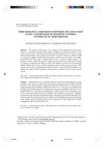
It is vital to understand the mathematics of how the coupled tank system behaves. System modeling involves developing a mathematical model by applying the fundamental physical laws of science and engineering in this system. Nonlinear dynamic model with time-varying parameters are observed and steps are taken to derive each of the corresponding linearized perturbation model from the nonlinear model [1]. To maintain or control the water level at some desired value, the input flow rate need to be adjusted by adjusting the pump voltage. In process control terms, the input flow rate is known as the manipulated variable. A schematic diagram of the coupled-tank apparatus is shown in Fig. 1.
The industrial application of liquid level control is huge especially in chemical process industries. Usually, level control exists in some of the control loops of a process control system. An evaporator system is one example in which a liquid level control system is a part of the control loop. Nowadays, the process industries such as petro-chemical industries, paper making and water treatment industries require liquids to be pumped, stored in tanks, and re-pumped to another tank. The control of liquid in tanks and flow between tanks is a basic problem in the process industries. In the design of control system, a complicated mathematical model is applied that has been obtained from fundamental physics and chemistry. Many other industrial applications are concerned with level control, may it be a single loop level control or sometimes multi-loop level control. In some cases, level controls that are available in the industries are for interacting tanks. Hence, level control is one of the control systems variables which are very important in process industries [1]. In process control it is common practice to use PI controller for steady state regulation and to use manual controller for large changes [2]. PI controller is widely used in industrial applications of liquid level control and
Figure. 1. Schematic diagram of coupled tank apparatus.
Manuscript received July 29, 2013; revised November 12, 2013. ©2014 Engineering and Technology Publishing doi: 10.12720/joace.2.3.316-321
316
Journal of Automation and Control Engineering Vol. 2, No. 3, September 2014
Similarly,
A simple nonlinear mathematical model is derived with a help of this diagram. Let H1 and H2 be the liquid level in each tank, measured with respect to the corresponding outlet, considering a simple mass balance, the rate of change of liquid into the tank. Thus for each of tank 1 and tank 2, the dynamic equation is developed as follow. √
√
(1)
√
√
(2)
√
(√
√
√
√
√
)
(
)
( )
( )
(
√
( )
( )
(
(√(
(
)
(8)
)
( ) (9)
√
)
( )
( ) (10)
By rearranging and rewriting in abbreviated manners, (
) ( )
( )
( )
(11)
(
)
( )
( )
(12)
( )
√
√
(4)
√
√
√
)
√
√
)
√
(√
√
√
√ )
(5)
√
)
√
√ )
(√(
)
√
(6)
√
For small perturbation, ))
√
((
√
))
√
©2014 Engineering and Technology Publishing
√
Simultaneously express (11) and (12); into a form that relates between the manipulated variable, q1 and the process variable, h2, the final transfer function equation can be obtained as
Therefore consequently, √
√
√
√
(3)
)
(√
√
(7)
( )
√
Subtracting (1) and (2) from (3) and (4), the equation will become
((
)
Performing Laplace transforms on (7) and (8) and assuming that initially all variables are at their steady state values.
√
√(
√
(
where
√(
√
)
√
√ Abiding by this approximation, (7) and (8) are established
√
)
√
And
where H1, H2 = height of liquid in tank1 and tank2 respectively A1, A2 = cross-sectional area of tank1 and tank2 respectively Qo3= flow rate of liquid between tanks Qi1, Qi2 = pump flow rate into tank1 and tank2 respectively Qo1, Qo2= flow rate of liquid out of tank 1 and tank 2 respectively. α1, α2, and α3 are proportionality constant which depends on the coefficients of discharge, the cross-sectional area of each orifice and the gravitational constant. For a linearized perturbation model, suppose that for set inflows Qi1 and Qi2, the liquid level in the tanks is at some steady state levels H1 and H2. Consider small variations in each inflow, q1 in Qi1 and q2 in Qi2. Let the resulting perturbation in level be h1 and h2 respectively. From (1) and (2), the following equations can be derived [1]. For tank1 ( ) ( )
For tank2 (
√
317
Journal of Automation and Control Engineering Vol. 2, No. 3, September 2014
( ) ( )
)
(
(
(
)
The parameters used for simulation as shown in Table I was tested experimentally in previous work [1].
)
III. COUPLED TANK CONTROLLER DESIGN USING PI CONTROLLER
Based on the dynamic equations (7) and (8) a Simulink block diagram of the coupled-tank system for a linear model can be implemented as shown in Fig. 2.
Proportional-Integral is as type of feedback controller whose output, a control variable (CV), is generally based on the error (e) between some user defined set-point (SP) and some measured process variable (PV). Each element of the PI controller refers to a particular action taken on the error [11]. ( ) Proportional: Error multiplied by proportional gain, Kp. This is an adjustable amplifier. In many systems Kp is responsible for process stability: too low and the PV can drift away; too high and the PV can oscillate. Integral: The integral error is multiplied by integral gain Ki. In many systems Ki is responsible for driving error to zero, but set Ki too high is to invite oscillation or instability or integrator windup or actuator saturation. Tuning of a PI involves the adjustment of Kp and Ki to achieve some desired system response Ziegler-Nichols on-line tuning method can be considered as one of the earliest closed-loop tuning method. This method requires proportional controller gain Kp to be increased until the control loop oscillates with constant amplitude. The value of the proportional gain that produces sustained oscillations is called ultimate gain Ku. The period of this sustained oscillation is called ultimate period Tu. Valve or motor pump is also taken into consideration that relates the commanded input with actual input flow going into the first tank. This simulation is carried without loading disturbance, that is second motor pump in the second tank is switched off. Fig. 4 illustrates the complete simulation diagram for the linear system of a coupled-tank.
Figure. 2. Linear model of coupled tank system simulation.
The valve/pump actuator can be also modeled as it is, in the fast, an important control element in the plant. The following differential equation describes the valve/pump actuator is dynamics [9], [10]. The valve/pump actuator has been modeled in simulation for linear system as shown in Fig. 3. () ( ) ( ) (14) where Tc is the time constant of the value/pump actuator. qi(t) is the time –varying input flow rate. Qc (t) is the computed or the commanded flow rate. TABLE I: PARAMETERS OF COUPLED TANK SYSTEM Name Cross Section Area Of the couple tank reservoir Proportionality Constant that depends on discharge coefficient, orifice cross Sectional area and gravitational Constant Pump motor time constant
Expression A1&A2
Value 32cm2
Subscript i denotes Which tank it refers
α1 14.3 cm2/3 / sec
Tc
α2 14.3 cm2/3 / sec
α3 20 cm2/3 / sec
Figure. 4. Simulink diagram to simulate PI controlled coupled– tank..
IV. COUPLED TANK CONTROLLER DESIGN USING MRAC
1sec
The general idea behind Model Reference Adaptive Control (MRAC) is to create a closed loop controller with parameters that can be updated to change the response of the system. The output of the system is compared to a desired response from a reference model. The control parameters are updated based on the error difference
Figure. 3. Valve/pump actuator simulation.
©2014 Engineering and Technology Publishing
318
Journal of Automation and Control Engineering Vol. 2, No. 3, September 2014
between the plant output and the reference model output [12], [13] which can give the better results as compare to the classical control. In this paper, the MRAC can be designed such that the globally asymptotic stability of the equilibrium point of the error difference equation is guaranteed. To do this, Lyapunov Second Method is to be used, where the differential equation of the adaptive law is chosen so that certain stability conditions based on Lyapunov theory is satisfied. The plant model of the coupled-tank system is ( )
)
(
(
Therefore, the adaptation mechanism can be
derived as ( (
) )
In setting up the adaptation mechanism, the adaptation weights and for the pair; the proportional adaptation and integral adaptation should be selected which can be accomplished through a trial-and–error procedure. The Simulink block diagram of MRAC for coupled- tank system as shown in Fig. 5.
( )
)
where h2(s) is water level in tank2 u(s) is control signal By substituting the parameters in the plant model, it will become ( )
( )
The plant will be tested with fast response specification reference model. So that the reference model has 1% as its percentage overshoot and settling time (which is based on 2% criterion) is 15 sec. based on the desired specification, a standard second order transfer function was chosen as reference model. ( )
Figure. 5. Simulink diagram to simulate MRAC controlled coupled– tank.
( )
( )
V. SIMULATION RESULT AND ANALYSIS
( )
The main objectives in this paper are to control the level of the tank2 by controlling the flow rate of liquid in the tank1. Where the desired performance specification for this system can be listed as follows The set point or the desired water level in the second tank is set to be 9 cm at first. Good transient response should be observed. No offset or steady state error should be observed. Fig. 6 shows the simulation result of PI controller for different values of Kp and Ki. That had been tuned using Ziegler –Nichols for the linear system model where this tuning is done by using Matlab Simulink.
where hm(s) reference model output r(s) reference input signal In this paper the controller is an adaptive PI controller that will be used to control the level in the second tank h2 by adjusting the parameters of the PI controller via MRAC by applying Lyapunov technique. The transfer function of this controller as ( )
)( ( )
(
( ))
The derivation of MRAC using Lyapunov Method for coupled-tank system can be stated as follow: Step1: Derive differential equation for e that contains the adjustable parameters Kp and Ki. ⃛ ⃛ ⃛ ̈
( ̇ ̇
(
̇) ̇ (15) ) has
̈
)
̇ Step2: A suitable Lyapunov function ( ̈ ̇ been chosen based on (15) ( ̈ ̇
where definite.
)
̈
̇
©2014 Engineering and Technology Publishing
Kp =23, Ki =3
14
Kp =13, Ki =0.9
12 10 8 6 4
0
̇
Kp =74.81, Ki =7.48
2
, so that V is positive
Step3: For stability, ̇ ̇ < 0. ̇ ̈⃛ ̇ ̈
setpoint (9 cm)
16 Water level in tank2 (cm)
⃛
Step response of the system using PI controller 18
̇
0
20
40 60 Time(sec)
80
100
Figure. 6. Output response of couple tank system using PI controller.
319
Journal of Automation and Control Engineering Vol. 2, No. 3, September 2014
Initially, the transient response of the system is not satisfactory, there is a fluctuation in the response shape and gives a very high overshoot. In practice, this will affect the system and may cause the over flow in the level of the tank2. Moreover the steady state error is high and the settling time is large too. This requires the controller parameters to be adjusted according to the assumption that reducing will slightly reduce the oscillation and reducing will stabilize the system even more. After refine tuning the steady state error eliminates even as the settling time and overshoot are decreased. This paper also presents the results that were obtained using MRAC-PI controller for a couple-tank system. MRAC controller using Lyapunov Method has been successfully designed to control water level of the second tank. Fig. 7 illustrates the responses of the MRAC controller using Lyapunov method for a couple tank systems for different values of the adaption gain and . The best values were found at , and the output response h2 has good tracing as well as the reference model output hm. Step response of the system using MRAC 18
TABLE II. PERFORMANCE SPECIFICATION COMPARISON BETWEEN PI AND MRAC CONTROLLER Performance
PI controller
specification Rise Time
Kp=13 and Ki=0.9 10.43 sec
MRAC =32 and
Overshoot
17.55 %
0
Settling Time
51.4 sec
14.4 sec
Steady State Error
0
0
=6.43
12.19sec
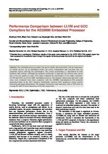
Table II summarizes the comparison of the output of level tank 2. The characteristic response difference can be clearly seen between two controllers. The PI controller has faster response than the MRAC controller with the rise time of 10.43 second. On the other hand, the output response using the MRAC has no overshoot compared to that using the PI controller. Compared with the PI controller, the MRAC controller has a shorter settling time of 14.4 second. Both have zero steady state response errors. However, the response using the MRAC controller has reached to the desired level faster than that of the PI controller.
water level in tank2 (cm)
16
VI. CONCLUSION
14 12
In conclusion, this paper successfully elaborates the designing of two controllers. A model for couple tank system is successfully designed and developed such that the height level tank 2 can be controlled at any desired level without over flow from the tank. The main contributions of this paper are deriving the mathematical model of the system, simulate the system with Matlab Simulink and applied different control strategies to the system such as PI controller and MRAC controller to control the liquid level in the tank. In the couple tank system, the most required criterion is that the system has a small or no overshoot and zero steady state error. PI controller is simple to design and easy to calculate the controller parameters using Zeigler-Nichols method, while in the MRAC the stability of the closed-loop system and the convergence of the adaptation error are assured by the Lyapunov theory of stability. The simulation result presented the conventional PI controller improved in the steady state region, while the MRAC improved in the transient and steady state regions of the response. Hence it can be concluded that MRAC yields better result than PI controller.
10 8
Ref. signal Ref. model
6
Plant response 1 =4 , 2=1
4
Plant response 1 =27 , 2=6
2 0
Plant response 1 =32 , 2=6.43 0
20
40 60 Time(sec)
80
100
Figure. 7. Output response of couple tank system using MRAC.
Fig. 8 shows the step response of the output level tank2 versus the time, the two responses have been plotted on the same graph to be compared. As can be seen, the solid line represents the desired level in the second tank, while dash dotted line represents the height level tank2 using PI controller and the dashed line represents the height level tank2 using MRAC, with some differences between the characteristic of the responses. Step response of the system using( PI and MRAC) controller Setpoint (9 cm) PI MRAC
water level in tank2 (cm)
12 10
ACKNOWLEDGMENT
8
This work was supported in part by the College of Electronic Technology. Department of Control Engineering. M. SAAD thanks College of Electronic Technology for their support.
6 4 2 0
0
20
40 60 Time(sec)
80
REFERENCES
100
[1]
Figure. 8. Comparison responses of PI and MRAC controller
©2014 Engineering and Technology Publishing
320
A. H. Yousif, S. Buyamin, and N. Abdul Wahab, “Integral time absolute error minimization for pi controller on coupled- tank liquid
Journal of Automation and Control Engineering Vol. 2, No. 3, September 2014
[2]
[3]
[4] [5] [6]
[7]
[8]
[9]
[10] [11]
[12] [13]
level control system based on stochastic search techniques,” Jurnal Teknologi (Sains & Kej.) Keluaran Khas, pp. 381– 402, Jan 2011. J. Malmborg and J. Eker, “Hybrid control of a double tank system in control applications,” in Proc. IEEE International Conference, 1997. H. Pan, H. Wong, V. Kapila, and M. S. de Queiroz, “Experimental validation of a nonlinear backstepping liquid level controller for a state coupled two tank system,” Control Engineering Practice, vol. 13, pp. 27-40, 2005. B. Stenlund and A. Medvedev, “Level control of cascade coupled flotation tanks,” Control Engineering Practice, pp. 443- 448, 2002. N. B. Almutairi and M. Zribi, “Sliding mode control of coupled tanks,” Mechatronics, pp. 427-441, 2006. T. L. Seng, M. Khalid, and R. Yusof, “Tuning of a neuro-fuzzy controller by genetic algorithms with an application to a coupled-tank liquid-level control system. engineering applications of artificial intelligence,” Engineering Applications of Artificial Intelligence, vol. 11, no. 4, pp. 517-529, 1998. S. N. Engin, J. Kuvulmaz, and V. E. Ömürlü, “Modeling of a coupled industrial tank system with ANFIS,” in MICAI Advances in Artificial Intelligence, 2004, pp. 804-812. M. S. Ramli, R. M. T. R. Ismail, M. A. Ahmad, S. M. Nawi, and M. A. M. Hussin, “Improved coupled tank liquid levels system based on swarm adaptive tuning of hybrid proportional-integral neural network controller,” American J. of Engineering and Applied Sciences, pp. 669-675, 2009. M. N. b Mahyuddin, “Direct model reference adaptive control of coupled tank liquid level control system,” Ms. Eng. Thesis, Dept. Mechatronics and Automatic Control, Universiti Teknologi Malaysia, October 2005. P. C. Chau. Process Control: A First Course with MATLAB. Cambridge University Press. 2002 B. Kumar and R. Dhiman, “Optimization of PID controller for liquid level tank system using intelligent techniques,” Canadian Journal on Electrical and Electronics Engineering, vol. 2, pp. 531-535, November 2011. K. J. Astrom and B. Wittenmark, Adaptive Control, Addison-Wesley, ch. 5, 1989. A. Xiong and Y. Fan, “Application of a PID controller using mrac techniques for control of the dc electromotor drive,” in Proc. International Conference on Mechatronics and Automation, Harbin, China, August 2007, pp. 2616-2621.
©2014 Engineering and Technology Publishing
321
M. Saad was born in Baniwalid in 1983, received B. E & M. E degrees in Control Engineering & Mechatronics and Automatic Control from The Higher Institute of Electronics/ Bani-walid, Libya & Universiti Teknologi Malaysia, Johor, Malysia, in 2006 and 2009 respectively. Currently, he is a Lecturer in the Department of Control Engineering at College of Electronic Technology, Bani-walid, Libya. He has published one conference paper. His research interest covers Automatic control, process instrumentation and modern control theory. Mr. Mustafa is a member of IEEE. A. Albagul was born in Baniwalid in 1968. He received his B.Sc. degree in electronic engineering (control engineering), The Higher Institute of Electronics, Baniwalid, Libya, 1989. MSc, in control engineering, University of Bradford, Bradford, UK, 1993. Ph.D, in electrical and electronic engineering, University of Newcastle upon Tyne, UK in 2001. His research interests are Control Systems, System Dynamics and Modeling, Smart Sensors and Instrumentation, Robotics and Automation. He was an Assistant Professor and then Associate Professor at the Department of Mechatronics Engineering, Faculty of Engineering, International Islamic University Malaysia from 2001 to 2006. He is currently a Professor at the Department of Control Engineering, College of Electronic Technology Baniwalid, Libya. Prof. Albagul is a MIEEE, MIEEE Control System Society, MIEEE Robotic and Automation Society, MIEEE Measurement and Instrumentation Society and Member of Libyan Engineers Society. He has many publications in refereed international journals and conferences. Y. Abueejela was born in Baniwalid in 1979, received B. E & M. E degrees in Control Engineering & Mechatronics and Automation systems from Tripoli university, Tripoli, Libya & University of Ton Husen onn, Malaysia, Johor, Malysia, in 2006 and 2009 respectively. He is a Lecturer in the Department of Control Engineering at College of Electronic Technology, Bani-walid, Libya. He has published two conference papers. His research interest covers Automation control and Robotics.