WSEAS TRANSACTIONS on SYSTEMS and CONTROL
Mohammed Hussin Al-Mola, Musa Mailah, Pakharuddin Mohd Samin, Abdul Halim Muhaimin, Mohd Yunus Abdullah
Performance Comparison between Sliding Mode Control and Active Force Control for A Nonlinear Anti-Lock Brake System MOHAMMED HUSSIN AL-MOLA1, MUSA MAILAH1, PAKHARUDDIN MOHD SAMIN 2, ABDUL HALIM MUHAIMIN1 MOHD YUNUS ABDULLAH1 1 Department of Applied Mechanics & Design Faculty of Mechanical Engineering Universiti Teknologi Malaysia 81310 Skudai, Johor MALAYSIA 2 Department of Aeronautics, Automotive and Ocean Engineering Faculty of Mechanical Engineering Universiti Teknologi Malaysia 81310 UTM Johor Bahru, Johor MALAYSIA
[email protected],
[email protected],
[email protected] Abstract: - The Anti-lock braking system (ABS) is the most common safety system in the vehicles, which works to increase the generating braking force between the tire and the road surface in way to keep the stability in vehicles during braking. The high nonlinearity due to the interaction between the tire and road, the uncertainties in vehicle dynamics always exist and using the standard PID controller will not be accurate enough to the extent required to deal with the uncertainties. Two robust control techniques, the sliding mode control (SMC) and an intelligent active force control (AFC) that both of them deal with the dynamic systems to provide durability and quell the unrest that may found in the system. In this paper highlights the ability of this proposed technique to improve the dynamic system robustly by combining them with standard PID in one control scheme (PID-AFC) comparing with (PID-SMC). Results showed the robustness of AFC and solo performance to improving the slip track without chattering phenomenon and thus reduce the stopping distance of the vehicle compared to other control schemes.
Key-Words: - Anti Lock Brake System; Active Force Control; Sliding Mode Control; Proportional-IntegralDerivative Controller; Robust control; Wheel Slip in the acquisition this kind of vehicles by the consumers. Therefore, it became necessary to focus on safety. Beforehand, the anti-lock brake system proposed to decrease the stopping distance of airplanes and since that time, it knows as one of the customary safety methods offered on most ground vehicles sold recently because of their highly supporting the drivers stop the vehicle in the safest stop. The system parameters basically governed by the road conditions, therefore; the performance of ABS can be not sufficient and acceptable all the time. Moreover, the noise and highly uncertain are the most common problems associated with sensors [1]. Two robust controllers have been applied; firstly, robust technique known as sliding mode control used to solve the chattering phenomenon that might happen in the system [2-3]. Applying the
1 Introduction It is well known that the antilock braking system (ABS) adapts the vehicle to keep on steerability by preventing the wheel lock during braking. However, it has some limitations as follows: slip oscillates around the peak friction point, many experiment are required for tuning the ABS system in trial and error manner. It’s only activating when the wheels are beginning to get lock-up. Otherwise; will lead to the loss of stability in steering the vehicle and it would be difficult to control the steering wheel manually any longer, which may result in severe accidents and injuries. Therefore; ABS does not necessarily shorten the stopping distance but, it does help to keep the vehicle under control during hard braking. Nowadays, the ground vehicles with high speeds have become more common due to the high demand
E-ISSN: 2224-2856
101
Volume 9, 2014
WSEAS TRANSACTIONS on SYSTEMS and CONTROL
Mohammed Hussin Al-Mola, Musa Mailah, Pakharuddin Mohd Samin, Abdul Halim Muhaimin, Mohd Yunus Abdullah
sliding mode controller on ABS designed with electric brake actuator was by [4]. Another trial to use this technique to evaluate the performance of ABS was by [5-6] to optimize the brake torque by considering the friction force as a result and uses the sliding mode with observer to find it. In [7], was investigating the ability of the SMC during braking operation to use the maximum value of road friction force on the wheels to find the algorithm that has ability to deal with the variety of system parameters. it has been proposed to show the adapting and tracking a desired slip ratio of the wheel during braking operation was by [6, 8-9]. Adaptive sliding mode control has been done by [10], it represents control method that focuses on controlling the variable different between the two common velocities in ABS (vehicle and wheel) in other words, the slip velocity. The objective of this control which is combined between the traditional SMC and the adaptive law is to prove the stability after estimate the road adhesion coefficient. Secondly, the proposed robust intelligent technique known as an active force control (AFC), has proposed in this paper and has been shown to be far superior compared to the standard PID control method in control of various dynamical systems [11-19]. This technique used widely in improving the movement of articulated of robot arm in both the theoretical and laboratory studies [12], where it added a remarkable effective improvement in the arm movement. It has been implement on two degrees of freedom Wagner brake model with standard PID controller and fuzzy logic to suppress the wobbling motion in the rotating disc brake system and the realized results were positive for adapt the brake model With this technique [13-14]. This technique has been used in laboratory on the active suspension system and the results were positive to improve the dynamic performance [1519]. Also proposed by [20] on two degrees of freedom of a spacecraft pitch attitude control enhanced with PD controller and showed impressive results on the system. The method has been used on the ABS and showed positive results in the control of the vehicle behavior during panic braking and provide optimum ratio for the coefficient of sliding in order to prevent the wheel from being totally locked under nonlinearities, parametric uncertainties [21-22]. Recent research used a hybrid control scheme based on AFC has been applied to ABS by enhancing with other control methods [23]. The system can be easily achieved using this technique for different road profile to keep the tire slip ratio corresponding to the peak traction coefficient during braking.
E-ISSN: 2224-2856
2 The system to be controlled Quarter vehicle model, the free body diagram in Fig. 1 represents the experimental mechanism of quarter vehicle model which describes the linear movement of the vehicle and rotational movement of the wheels under braking conditions [24-27]. The model is quite simple; in spite of this it maintains the basic characteristics of the actual system.
Fig. 1: Free body diagram of quarter vehicle model The governing equations of the motion of the dynamic system were based on Newton’s second law, starting by the upper and lower wheels respectively, and they can be written as:
J11 Ft r1 (d11 S U T B )
(1)
J 22 (Ft r2 d 22 S L )
(2)
The tractive force Ft in (1) and (2) views the road friction force multiplying the road coefficient which is given by the Coulomb law:
Ft ( )Fr
(3)
The normal force Fr , it can be calculated by using the following equation:
Fr
d 11 S U T B M g
(4)
L (sin ( )cos )
The φ is the angle between the normal at the contact point and the line L. increase the force on the wheel led to appear the slippage between the tire and the road surface.
102
R 22 R11 , 2 0 R 22
(5)
Volume 9, 2014
Mohammed Hussin Al-Mola, Musa Mailah, Pakharuddin Mohd Samin, Abdul Halim Muhaimin, Mohd Yunus Abdullah
WSEAS TRANSACTIONS on SYSTEMS and CONTROL
S slide E slip .E slip
R1: radius of the driven wheel, R2: radius of the drive wheel, ω1: angular speed of the upper wheel, ω2: angular speed of the lower wheel, J1: moment of inertia of the driven wheel, J2: moment of inertia of the drive wheel, Mg: moment of gravity and TB: braking torque
Where E slip= S*- S, S* the target slip and λ is a strictly positive constant. Ė slip is the derivative of E slip:
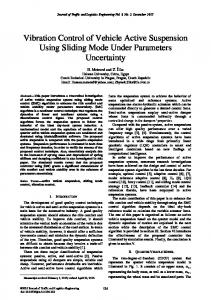
Road Adhesion Coefficient
Regarding to the friction coefficient of wheel slip toward the road, Fig. 2 shows the approximating relation by following formula [27] to get the road adhesion coefficient vs. wheel slip values.
E slip
0.35 0.3 0.25 0.2 0.15 0.1 0.05 0.1
0.2
0.3
0.4
0.5
0.6
0.7
0.8
0.9
dE slip dt
E slip (k 1) E slip (k ) ts
1
Wheel Slip
Fig. 2: Curve of road condition
( ) c1 c 2 2 c 3 3
c 4 p a p
(6)
2.1 PID Controller Proportional-Integral-Derivative controller, the widely used in a major control loops in the process control industries. Even it eliminates the instability of the passive dynamic behavior but, the respond of the dynamic system with PID controller is slow and need to enhance in order to improve the performance. Fig. 3: Phase-plane of SMC phenomenon [7] The transfer function of the standard PID control algorithm can be written as follows:
u (t ) K pe (t ) K i e (t )dt K d
d e (t ) dt
(7)
Where; Kp: Tuning parameter of proportional gain, Ki: Tuning parameter of integral gain, and Kd: Tuning parameter of derivative gain
2.2 Sliding mode control (SMC) In this study, the sliding-mode control theory is adopted to design the controllers because of its robustness [7]. The sliding-mode index S slide is defined as:
E-ISSN: 2224-2856
(9)
Where; ts is the sampling time. In Fig. 11, the sliding surface S slide ¼ 0 separates the phase plane into two semi-planes: one is S slide > 0 and the other is S slide < 0. Initially, sliding-mode switching control laws are adopted in the design of the controller, which give rise to discontinuous control signals and, as a consequence, chattering. In general, smoothing out the control discontinuity in a thin boundary neighboring the sliding surface can eliminate chattering.
0.4
0 0
(8)
Fig. 4: Schematic diagram of PID-SMC
103
Volume 9, 2014
WSEAS TRANSACTIONS on SYSTEMS and CONTROL
Mohammed Hussin Al-Mola, Musa Mailah, Pakharuddin Mohd Samin, Abdul Halim Muhaimin, Mohd Yunus Abdullah
2.3 Active Force Control (AFC) This strategy created by each of Hewit and Burdess (1981), who proposed the idea of AFC which is derived from the Newton’s second law of motion such as a rotating mass [11], we have:
T
total
J
(10)
Where; Ttotal is the sum of all torques acting on the dynamic body, J is the moment of inertia, and α is the angular acceleration. The objective of this control scheme is to control the dynamic system in order to ensure that the system will maintain its stability even with the presence of any external sudden disturbances [11]. It is based on the estimation of inertia or mass of proposed dynamic system with the precise values, and force or acceleration signal measuring which is induced by the system [19, 23]. For the ABS that will be embedded with the AFC scheme, the equation of motion becomes:
T B Q J 11
Fig. 4: AFC concept applied to the system
3 Results and Discussion The system has been simulated by using MATLAB and Simulink (s-function), PID controller and AFC as illustrated in Fig. 5.
(11)
AFC
Wheel Stop
Where; TB is the brake torque, Q is the disturbance torque, J1 is the moment of inertia of the upper wheel. The physical quantities directly need to be measured from the system are the actuating force and the vehicle acceleration which should be done by some sensing elements. The estimated disturbance torque Q′ can be computed by the equation [22-23]:
Q
TB E m 1R1 R1
Vehicle Stop Vehicle speed Wheel speed 0.2
General Scope
Tb Slip ratio
mu Fn
ABS
Ft
Fig. 5: The Simulink block diagram of PID-AFC scheme
(12)
After simulate the passive dynamic behavior with the simulation parameters [24, 27] are as follows: radius of the upper wheel= 99.5*1e-3 m, radius of the lower wheel = 99*1e-3 m, moment of inertia of the upper wheel= 7.5281*1e-3 kgm 2 , moment of
The principle of the AFC applied to the ABS as illustrated in Fig. 4. In this work, AFC method was implement to the ABS using MATLAB/Simulink and performed by (s-function) method for the dynamic model. The comparison was made to enhance the standard PID as other closed-loop control with the robust techniques in this paper. The aim of this control scheme is to ensure the system will remain stable and robust even under external disturbances that might affect suddenly to the system from the road condition, external environment climate during the function of braking case.
E-ISSN: 2224-2856
slip
PID Controller
inertia of the lower wheel= 25.603*1e-3 kgm 2 , viscous friction coefficient of the upper wheel= 1.2*1e-4 kgm 2 / s , viscous friction coefficient of the lower wheel= 2.25*1e-4 kgm 2 / s , reference slip=0.2, static friction of the upper wheel=3*1e-3, static friction of the lower wheel= 93*1e-3, and moment of gravity acting on balance lever=19.6181 Nm . The PID controller gains were tuned heuristically. To get the suitable values for the dynamic system, the gains were used are; 28, 19, and 0.6 respectively. Fig. 6 (a), shows the wheel
104
Volume 9, 2014
WSEAS TRANSACTIONS on SYSTEMS and CONTROL
Mohammed Hussin Al-Mola, Musa Mailah, Pakharuddin Mohd Samin, Abdul Halim Muhaimin, Mohd Yunus Abdullah
speed and slip ratio respectively during panic braking with/without ABS under 1800 r.p.m.
2000
Vehicle speed Wheel speed
1800
Angular speed (r.p.m)
1600
Without ABS, the wheel speed drop directly to zero after 0.3 second of applying braking force, and locked at the beginning braking case. While with ABS function, there is no locking up in the wheel till the vehicle stop. And Fig. 6 (b), the results in a slip value of 1 within 0.3 second with no ABS and how the system followed the reference slip with ABS.
1400 1200 1000 800 600 400 200 0 0
0.2
0.4
0.6
0.8
1
1.2
1.4
Time (s)
(a). Passive ABS 2000
No ABS ABS Reference
Vehicle speed Wheel speed
1800
1600
Angular speed (r.p.m)
Angular Speed (r.p.m)
1500
2000
1000
500
0
1400
1200
1000
800
600
400
200
-500 0
0.2
0.4
0.6
0.8
1
1.2
0
1.4
0
0.2
0.4
0.6
0.8
1
1.2
1.4
Time (s)
Time (s)
(a). Wheel speed
(b). PID scheme 2000
1
No ABS ABS Reference
0.9
1600
Angular speed (r.p.m)
0.8
Vehicle speed Wheel speed
1800
0.7
Slip
0.6 0.5 0.4 0.3
1400 1200 1000 800 600 400
0.2
200
0.1
0 0
0 0
0.2
0.4
0.6
0.8
1
1.2
0.2
0.4
0.6
0.8
1
1.2
1.4
Time (s)
1.4
(c). PID-SMC scheme
Time (s)
(b). Slip Ratio 2000
Vehicle speed Wheel speed
1800
Fig. 6: During Panic braking (No ABS) Angular speed (r.p,m)
1600
Fig. 7 (a), shows the passive dynamic system of the ABS. The unstable behavior of the wheel speed, denoting to the unsteerable and yawing movement during braking case. While in Fig. 7 (b), Fig. 7 (c), and Fig. 7 (d) disappeared by applying the control schemes which led the system stable till the vehicle stop. Taking into consideration the system stability with using the proposed technique.
1400 1200 1000 800 600 400 200 0 0
0.2
0.4
0.6 0.8 Time (s)
1
1.2
1.4
(d). PID-AFC scheme Fig. 7: Vehicle vs. wheel speeds during panic braking
E-ISSN: 2224-2856
105
Volume 9, 2014
Mohammed Hussin Al-Mola, Musa Mailah, Pakharuddin Mohd Samin, Abdul Halim Muhaimin, Mohd Yunus Abdullah
WSEAS TRANSACTIONS on SYSTEMS and CONTROL
The estimated mass (EM) need to be chosen for the dynamic system in order to implement the active force control. And is often worth between 0 and 1 as a percentage of the mass required for intelligent technique, as shown in the Fig. 8, it has been used several values of the estimated mass (EM) between (0.9-8.0) kg and it turns out that the system interact with the decrease in the value of the mass until stabilized at 0.9 kg perform effectively. Therefore; the decreasing of the EM values lead to improve the response of the slip ratio at 0.9 kg as shown in Fig. 8.
0.35
0.3
Slip
0.25
0.2
0.15
0
0.25
0.2
0.4
0.6
0.8
1
1.2
1.4
Time (s)
(b). Slip Ratio Fig. 9: During Panic braking (ABS) via three control schemes
0.2 Slip
Passive PID PID+SMC PID+AFC
0.15 Decreasing the EM values EM=0.9 Kg EM=4.0 Kg EM=5.0 Kg EM=6.0 Kg EM=7.0 Kg EM=8.0 Kg
0.1 0.05 0 0
0.2
0.4
0.6 0.8 Time (s)
1
1.2
4 Conclusion
1.4
Fig. 8: Slip Ratio with different EM values In Fig. 9 (a), shows the stopping distance during panic braking of the vehicle via three control schemes. The passive control has longer stopping by 60 cm compare with the system under control methods. While the Slip Ratio as demonstrate in Fig. 9 (b) shows the system more stable and without any yawing phenomenon in the vehicle behavior and shows that the PID-AFC is more robust and superior in performance compare with the passive dynamic in stability and with standard PID-SMC controller in robustness.
References: [1] M.R. Akbarzadeh, K.J. Emami, and N. Pariz, "Adaptive discrete-time fuzzy sliding mode control for anti-lock braking systems", Proc.Annu. Meeting NAFIPS, pp. 554-559, 2002. [2] Utkin, V. I. (1993). Sliding mode control design principles and applications to electric drives. IEEE Transactions on Industrial Electronics, 40(1), 23-36. [3] Harifi, A., Aghagolzadeh, A., Alizadeh, G., & Sadeghi, M. (2008). Designing a sliding mode controller for slip control of antilock brake systems. Transportation Research Part C: Emerging Technologies, 16(6), 731-741 [4] Lin, F. J., Chiu, S. L., & Shyu, K. K. (1998). Novel sliding mode controller for synchronous motor drive. IEEE Transactions on Aerospace and Electronic Systems, 34(2), 532-542.
14
Stopping distance (m)
12 10 8 6 4
Passive PID PID+SMC PID-AFC
2 0 0
0.2
0.4
0.6
0.8
1
1.2
1.4
Time (s)
(a). Stopping distance
E-ISSN: 2224-2856
In this paper, robust intelligent active force controller proposed to compare with traditional sliding mode control and both are combination with a standard PID. This new robust technique is deal with the acceleration and actuated force of the dynamic system. The performance of the proposed strategy as PID-AFC demonstrate a robust behavior of the system during panic braking case and superior performance over the standard PID and PID-SMC controllers for the ABS. The results show the ability to steer the vehicle with this technique and presented the effectiveness to improve the performance.
106
Volume 9, 2014
WSEAS TRANSACTIONS on SYSTEMS and CONTROL
Mohammed Hussin Al-Mola, Musa Mailah, Pakharuddin Mohd Samin, Abdul Halim Muhaimin, Mohd Yunus Abdullah
[5] Drakunov, S., Ozguner, U., Dix, P., & Ashrafi, B. (1995). ABS control using optimum search via sliding modes. IEEE Transactions on Control Systems Technology, 3(1), 79-85. [6] Ünsal, C., & Kachroo, P. (1999). Sliding mode measurement feedback control for antilock braking systems. IEEE Transactions on Control Systems Technology, 7(2), 271-281. [7] Wu, M. -., & Shih, M. -. (2003). Simulated and experimental study of hydraulic anti-lock braking system using sliding-mode PWM control. Mechatronics, 13(4), 331-351. [8] Song, J. (2005). Performance evaluation of a hybrid electric brake system with a sliding mode controller. Mechatronics, 15(3), 339-358 [9] Jing, Y., Mao, Y., Dimirovski, G. M., Zheng, Y., and Zhang, S. (2009). Adaptive global sliding mode control strategy for the vehicle antilock braking systems. Paper presented at the Proceedings of the American Control Conference, 769-773. [10] El. Hadri, A., Cadiou, J. C., & Msirdi, N. K. (2002). Adaptive sliding mode control for vehicle traction. Proc.of the 15th IFAC World Congress, Barcelona, Spain. [11] J. R. Hewit, J. S. Burdess, “Fast dynamic decoupled control for robotics using active force control”, Mechanism and Machine Theory, vol. 16, no. 5, 1981, pp. 535 - 542. [12] Hussein, S. B., Jamaluddin, H., Mailah, M., & Zalzala, A. M. S. (2000). Hybrid intelligent active force controller for robot arms using evolutionary neural networks. Paper presented at the Proceedings of the IEEE Conference on Evolutionary Computation, ICEC, 1, 117-124. [13] M. H. A. Al-Mola, Robust intelligent active force controller for a Wagner brake model, Universiti Teknologi Malaysia, Faculty of Mechanical Engineering, 2009, Master thesis. [14] M. H. Al-Mola, M. Mailah, S. Kazi, A. H. Muhaimin, and M. Y. Abdullah, “Robust active force controller for an automotive brake system”, 3rd Intl. Conf. on Intelligent Systems Modelling and Simulation (ISMS 2012), 2012, pp. 467-472. [15] G. Priyandoko, M. Mailah, “Controller design for an active suspension of a quarter car model using fuzzy logic active force control”, Proc. of the 2nd Intl. Conf. on Mechatronics. May 2005, Kuala Lumpur, pp. 693-700. [16] Z. Omar, Modelling and simulation of an active suspension system using active force control strategy, Universiti Teknologi Malaysia, 2002, Master Thesis.
E-ISSN: 2224-2856
[17] K. Hudha, H. Jamaluddin, M. P. Samin, and R. A. Rahman, “Active roll control suspension system (ARCS) using active force control strategy on a new modified half car model”, Society of Automotive Engineers, Warrendale PA, 2003. [18] Mailah, M., and Priyandoko, G. Mechatronic implementation of an intelligent active force. International Review of Mechanical Engineering, 4(7), 2010, 899-907. [19] G. Priyandoko, M. Mailah and H. Jamaluddin, Vehicles active suspension system using skyhook adaptive neuro active force control, Mechanical Systems and Signal Processing, 23(3), 2009, 855-868. [20] R. Varatharajoo, C. T. Wooi, M. Mailah, “Two spacecraft attitude degree-of-freedom controller”, Advances in Space Research, vol. 47, no. 4, 2011, pp. 685-689. [21] W. Lutfi, “Modelling and control of intelligent antilock brake system”, Universiti Teknologi Malaysia, Desember. 2005, Malaysia: Master Thesis. [22] M. H. Al-Mola, M. Mailah, A. H. Muhaimin, and M. Y. Abdullah, “Intelligent active force controller for an anti-lock brake system application”, 1st Intl. Conf. on Systems, Control, Power, Robotics in Singapore (SCOPORO 2012), 2012. [23] M. Al-Mola, M. Mailah, A.H. Muhaimin, M.Y. Abdullah, P.M. Samin, "Fuzzy-based PID with iterative learning active force controller for an anti-lock brake system," International Journal of Simulation: Systems, Science and Technology, vol. 13, pp. 35-41, 2012. [24] Oniz, Y., Kayacan, E., & Kaynak, O. A dynamic method to forecast the wheel slip for antilock braking system and its experimental evaluation. IEEE Transactions on Systems, Man, and Cybernetics, Part B: Cybernetics, 39(2), 2009, 551-560. [25] Mills, V., Samuels, B., & Wagner, J. (2002). Modeling and analysis of automotive antilock brake systems subject to vehicle payload shifting. Vehicle System Dynamics, 37(4), 283310. [26] Rajamani, R. (2006) Vehicle Dynamics and Control. New York, NY, USA: SpringerVerlag. [27] “User’s manual” The Laboratory Antilock Braking System Controlled from PC, Inteco Ltd., Crakow, Poland, 2006.
107
Volume 9, 2014