Abstract- The demand for control of electric power for electric motor drive system and industrial control exists since many years. ... Some ad- vanced techniques are practiced in motor control applica- tions. .... decision matrix shown in table-II.
Letter Paper Int. J. on Recent Trends in Engineering and Technology, Vol. 7, No. 2, March 2012
Performance Comparison of PID and Fuzzy Control Techniques in Three Phase Induction Motor Control T. D. Dongale1, S. R. Jadhav2, S.V. Kulkarni3, T. G. Kulkarni4, R. R. Mudholkar5, M. D. Uplane6 1-4
Email: {tukaram.eln, eln.sjdhav, svkulkarni19, tushar.kulkarni19}@gmail.com 5,6 {rrm_eln, sensor}@unishivaji.ac.in Department of Electronics, Shivaji University, Kolhapur, India
Abstract- The demand for control of electric power for electric motor drive system and industrial control exists since many years. Variable-speed drives are designed when a motor is combined with a power electronics converter. By introducing variable speed for the driven load, it is possible to optimize the efficiency of the entire system and this is the area where the maximum efficiency gains are possible. The closed loop control strategies employed are legion and PID is seemed to be superior amongst them. However it further needs to be improved in terms of overshoot and settling time. So control strategies based on soft computing could be good alternative. This paper describes the implementation of controllers based on PID and Fuzzy Logic strategies. A comparative performance analysis demonstrates that the clever exploring of Fuzzy Logic control strategies circumvents the demerits of PID control strategies.
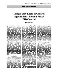
II. SYSTEM BLOCK DIAGRAM
Index Terms— PID, Fuzzy Controller, Simulink Model, Three phase inverter, Induction motor
The system block diagram is shown in fig.1. It is designed around PIC 16F877A. It includes inverter design, gate drive circuit, isolation and microcontroller. For the operation of variable frequency bridge inverter the required logic pulses are generated by using PIC microcontroller and are applied to gate drive circuit. The frequency for operation is read by microcontroller through Hall Effect speed sensor and current speed is sent to Simulink of PID or Fuzzy control technique through USART terminal of microcontroller. The gate drive circuit consists of opto-isolator provides isolation for microcontroller form the gate drive circuitry. The basic three phase voltage source inverter consists of six power MOSFETs with built in anti parallel diodes for freewheeling action. The IRFP-460 N- MOSFET operates as a switch. AC voltage from the power grid is rectified filtered and applied to three phase inverter as DC source. Power supplied to the motor is modulated by frequency generated by microcontroller. The speed sensed by Hall Effect sensor is displaying LCD [10].
I. INTRODUCTION AC motors are more popular with their integration in large number of applications like pumps, conveyors, machine tools, centrifugal machines, presses, elevators, and packaging equipment etc. The major benefits of using AC motor in a system are improved reliability, better performance, higher efficiency, easy scalability and feasibility of speed and torque control by different techniques. The techniques such as Rotor Resistance Control, Stator Voltage Control, Variable f, V/F Control, Slip Energy Recovery Scheme etc. play significant role in precisely controlling the speed of motors. Many researchers have reported the work on speed control of AC machines employing different control strategies [1-3]. The performance comparison of various drives reported in literature help the comprehensive understanding the drive option targeted for application of interest [5, 11, 13]. An induction motor supplied by an ac drive can operate over a good range of frequency, typically from 10Hz to 90Hz. This range of frequencies yields rotor speeds from zero rpm to the rated value. The ac drive can produce the rated torque at any frequency within this range from zero to the rated frequency. Some advanced techniques are practiced in motor control applications. Among these PID is most popular Algorithm. Some researchers have used Fuzzy, Fuzzy-PID and Neuro Fuzzy techniques in their applications. In the present work the three phase motor drive is proposed implemented using PIC microcontroller. © 2012 ACEEE DOI: 01.IJRTET.07.2.517
Figure 1. System Block Diagram
A. Three Phase Inverter Design Three phase inverter designed using power MOSFETs is as shown in fig.2. The inverse diode associated with the device is sufficient to operate the circuit at higher frequencies. MOSFET technology promises to use much simpler and efficient drive circuits with significant cost benefits compared to bipolar devices. High voltage capacitor is connected across the rectifier out to provide low impedance path for high frequency current at switching of power devices.
Letter Paper Int. J. on Recent Trends in Engineering and Technology, Vol. 7, No. 2, March 2012 threshold proportional to the supply VDD (3V-20 V). This MGD has two gate drive channels. C. Microcontroller PIC 16F877A The role of PIC16F877A is to generate PWM of desired frequency using timer/ counter module [4, 6]. It also monitors the sensed speed by Hall Effect sensor and sends it serially to Simulink designed for PID and Fuzzy control technique. According to present speed the Simulink model will generate thee control signal which is fed back to microcontroller for PWM variation. Microcontroller also displays the current speed in RPS (Rotation per Second) on 16x2 LCD. Figure 2.Three phase half bridge inverter
The conduction sequence of MOSFET is 612, 123, 234, 345, 456, 561, avoids conduction of two MOSFETs of the same branch at time. There must be some short time delay between turn off MOSFET and turn on MOSFET, which must be greater than or equal to turn-off time of MOSFET (HH20 nS). The Phase to neutral output waveforms are as shown in fig.4.
D. Hall Effect Speed Sensor In the present work a unipolar Hall Effect speed sensor MH 183 is used for sensing the speed. It incorporates advanced chopper stabilization technology to provide accurate and stable magnetic switch points. The design, specifications and performance have been optimized for applications of solid state switches [10]. III. PID AND FUZZY SIMULINK MODEL DEVELOPMENT Using Simulink facility of MATLAB the models for PID Controller and Fuzzy Controller have been developed for realtime motor speed control.
Figure 3. Real Time Controlling of three Phase Induction Motor
Figure 4. Inverter Output Waveforms (Simulated in PSIM software)
B. Gate Drive Using IC- IRS 2110 A single chip: IRS2110 serves the purpose of implementing gate drives including the circuitry that takes into account the voltage biasing of the high side MOSFETs [7, 8]. The IR2110 MOS gate driver IC has two channels controlled by TTL or CMOS compatible inputs. IRS2110 have the transition © 2012 ACEEE DOI: 01.IJRTET.07.2.517
A. PID Controller Simulink Design in MATLAB PID Tuner provides a fast and widely applicable singleloop PID tuning method for the Simulink PID Controller blocks. With this method the PID parameters can be easily tuned to achieve a robust design with the desired response time. The actual speed of motor is sensed by speed sensor using PIC controller and it sent serially to Simulink. As shown in fig.5 the Simulink block corresponding to constant is used to set desired speed. Here auto tune PID is used for tuning plant or system. The transfer function of motor system is a second order type that exhibits overshoot and large settling time which forms the metrics of performance in the present study.
Figure 5. PID Simulink Model
Letter Paper Int. J. on Recent Trends in Engineering and Technology, Vol. 7, No. 2, March 2012 B. Fuzzy Controller Simulink Design in MATLAB
develops a decision signal intending to maintain the speed. The program is developed in MPLAB environment with hitch c-compiler.
Figure 6. Fuzzy Simulink Model
Fig.6 shows Simulink design model for Fuzzy Controller. It contain query instrument for accepting the real time present speed of motor through serial port of PIC. The constant sets the reference speed. Error block generates the output which is the error between actual speeds and set speed that is applied to one input of Fuzzy controller and other to store the error in memory to compute a change in error. Multiplexer combine both inputs and gives it to Fuzzy controller. Real time scope is used to observe actual behavioral of a system. The instrument block is used to send output of Fuzzy Controller to PIC. The Fuzzy Inference Scheme (FIS) for Fuzzy controller is design using Mamdani method [11]. C. PID Simulation Model
Figure 8. Real Time PID Response
D. Fuzzy Simulation Model For speed control of induction motor using Fuzzy Controller, it is necessary to develop Fuzzy Inference System (FIS) in MATLAB environment. PID is one of the popular methods for many applications but it has certain limitations. Fuzzy control is another simplest method for control applications. It basically closely associated with the human’s decision making. It is rule based approach providing smooth control strategy [11, 12]. FIS designed the for speed control of induction motor as is shown in fig.9.
Figure.9. FIS Editor for FUZZY Controller by Mamdani’s Method Figure 7. Auto-Tune PID Tuning Response
Fig.7 shows the response of auto-tune PID controller. Auto-tune PID tuning response indicated little sluggish response in tracking the set point. The various performance metric parameters are shown in table-I. TABLE-I: SYSTEM PARAMETER
FOR
THREE PHASE INDUCTION MOTOR CONTROL
Fig.8 shows the tuned PID output response and real-time speed of induction motor. Depending upon set speed the error in speed is computed that is applied to the PID controller. Output of PID is passed over to PIC microcontroller to maintain the speed. Program embedded in microcontroller © 2012 ACEEE DOI: 01.IJRTET.07.2.517
Figure.10. Rule Viewer for FUZZY Controller by Mamdani’s Met hod
For this particular application, Mamdani’s controller is used, which has two inputs namely ‘error’ and ‘change of
Letter Paper Int. J. on Recent Trends in Engineering and Technology, Vol. 7, No. 2, March 2012 error’ and single output. Input and output variable ranges have been portioned by seven triangular membership functions labeled as ‘NL, NM, NS, Z, PS, PM, PL’. The error input is nothing but difference between the speed sensed using Hall Effect sensor and set point speed, and change of error is the difference between current speed and previous speed. The previous speed is stored in memory block which holds the speed data for particular instant of time. According to these inputs and control policy the rules are defined using decision matrix shown in table-II. TABLE-II: FUZZY R ULE BASE DECISION MATRIX FOR SPEED CONTROL
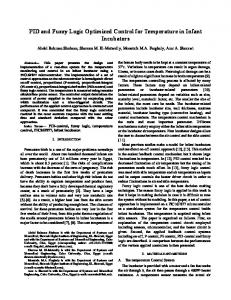
provide precise controlling action within their limits. PID controller is good due it ability of auto tuning. Upon tuning it tracks the set point. But it suffers from more settling time and overshoot. As evident from response curve (Figures 7 and 8) the PID in simulated and real time implemented forms has greater over and undes shoots besides longer settling time. PID has presented difficulties during tuning. This is where Fuzzy Control Fuzzy seems to be a promising control strategy. The figure 11 depicts the response of Fuzzy controller intended to drive the three phase induction motor. Fuzzy Controller has offered negligible settling time than PID controller and with almost no overshot. Comparison of experimental results of both the controllers reveals that that speed controlling of AC induction motor with Fuzzy controllers is smooth and easy than PID controlling method. REFERENCES
The rules have the following formatIF error is NL AND change of error is NL THEN output is NL IF error is NM AND change of error is PS THEN output is NS In all forty nine rules are defined as per the control demand needs the action. The rules are fired according to the inputs and decisions pertaining to output control signal are generated. This output is again sent back to the PIC microcontroller. Based on present speed it generates a PWM sequence for increasing or decreasing the speed. The system is operated in closed loop. The fuzzy inference process is shown in figure 10. The response of fuzzy simulation is shown in fig.11. It shows the settling time required and also the settled output for given input.
Figure 11. Real Time Fuzzy Controller Response for Three Phase Induction Motor Control
IV. RESULTS AND DISCUSSION Designing a suitable controller for three phase induction motor is a challenge. In practice non fuzzy control algorithms seems to be doing better on commercial level, yet scope exits to develop the newer control techniques based on soft computing. PID and FUZZY controllers are very efficient for speed controlling of three phase ac induction motor. They © 2012 ACEEE DOI: 01.IJRTET.07.2.517
[1] Gade S S, Shendge S B, Uplane M D, “Performance comparison of Auto Tune PID Controller with Conventional PID Controller,” International Journal IJCSC, Volume-1, Number1 of Jan 2010, serial number 39,pp. 273-277, ISSN: 09737391. [2] R. Arulmozhiyal, K Baskaran, N.Devarajan, J.Kanagaraj, “Real Time Matlab Interface for Speed Control of Induction Motor Drive using dsPIC 30F4011,” International Journal of Computer Applications (0975-8887) Volume 1-Number- 5. [3] Ashok Kusagur, Dr. S.F.Kodad, Dr.B.V.Sankar Ram, “Modeling, Design and simulation of an Adaptive Neuro- Fuzzy Inference System(ANFIS) for speed control of Induction motor”, International Journal of Computer Applications (0975-8887) Volume- 6,Number- 12, September 2010 [4]http://www.microch ip.com/wwwproducts/ Devices.aspx?dDocName=en010242 (PIC16F877A datasheet). [5] G. Chen, “Conventional and Fuzzy PID Controllers: An Overview”, 1996. [6 ]h tt p :/ /w w w. m ic r oc h ip .c o m / w w w p ro du c ts / Devices.aspx?dDocName=en010242 [7] http://www.irf.com/product-info/hexfet/ [8] http://www.irf.com/productinfo/cic/fsgatedriverics.html [9] www.variablefrequencydrives.net/ [10] MH 183 CMOS Unipolar Hall Switch.pdf. [11] Gade S S, Shendge S B, Uplane M D,”On line Auto Tuning of PID controller Using Successive Approximation Method,” IEEE Xplore,International conference on 12th – 13th March , ITC-2010 cochin. [12] Bart Kosko,”Neural network and fuzzy system- a dynamic approach to machine intelligence”, University of south California, Pentice Hall of India, 2001. [13] Chitra, Assistant Professor (senior), VIT University, Vellore, India, T.Meenakshi [14] Assistant Professor, Jansons Institute of Technology, India. J. Asha Professor, I.F.E.T. College of engineering, India. “Fuzzy logic controller for cascaded H-bridge multi level Inverter”, ISSN: 0975-5462 Vol. 2 no. 2 Feb. 2011. [15] Matlab, Simulink User Guide, the Math Works Inc, 2010.