7264
IEEE TRANSACTIONS ON POWER ELECTRONICS, VOL. 31, NO. 10, OCTOBER 2016
Performance Comparison of Three-Step and Six-Step PWM in Average-Current-Controlled Three-Phase Six-Switch Boost PFC Rectifier Laszlo Huber, Senior Member, IEEE, Misha Kumar, and Milan M. Jovanovi´c, Fellow, IEEE
Abstract—In this paper, a three-step PWM method for the average-current-controlled three-phase six-switch boost PFC rectifier is proposed. It is shown that the three-step PWM compared to the conventional six-step PWM exhibits a lower total harmonic distortion of the input currents and higher power factor. However, the three-step PWM, unlike the six-step PWM, is adversely affected by the duty-cycle limitations and has unbalanced conduction losses of the upper and lower switches of the three-phase rectifier bridge. The average-current control of the three-step and six-step PWM is illustrated with MATLAB/Simulink simulation waveforms and experimentally verified on a 3 kW prototype. Index Terms—Average-current control, discontinuous spacevector modulation (SVM), duty-cycle limitation, low-pass filtering and sampling, power factor (PF), segment detection, six-step PWM, three-phase six-switch boost PFC rectifier, three-step PWM, total harmonic distortion (THD), zero-sequence signal (ZSS) injection.
I. INTRODUCTION ODAY, the active three-phase power factor correction (PFC) rectifiers need to meet very challenging performance requirements. In the majority of applications, the input current of the active three-phase PFC rectifiers is required to have a total harmonic distortion (THD) less than 5% and a power factor (PF) greater than 0.99 [1]. One of the most cost-effective topologies that can meet these requirements is the three-phase six-switch boost PFC rectifier [2], which is usually implemented without a neutral-point connection. A number of control methods that can achieve a high quality of input currents in the three-phase six-switch boost PFC rectifier are available [3], [4]. Generally, approaches using direct control of input current versus, for example, direct power control, result in a better quality of the input currents [5]. Today, the control circuit is usually implemented with digital technology. One direct current control method, well suited for the digital implementation, is the average current control [6], [7]. In a three-wire three-phase applications because the sum of the phase currents is zero, the control can be implemented by having only two out of the three current controllers actively shaping the current at a given time. The desired current in the inactive-controller phase is obtained by the sum of currents of
T
Manuscript received August 10, 2015; accepted October 29, 2015. Date of publication December 8, 2015; date of current version May 20, 2016. Recommended for publication by Associate Editor T. Shimizu. The authors are with the Power Electronics Laboratory, Delta Products Corporation, Research Triangle Park, NC 27709 USA (e-mail:
[email protected];
[email protected];
[email protected]). Color versions of one or more of the figures in this paper are available online at http://ieeexplore.ieee.org. Digital Object Identifier 10.1109/TPEL.2015.2506554
the actively controlled phases. One implementation of this control method is based on dividing the line cycle of the input phase voltages into six 60° segments [six-step pulse width modulation (PWM)] as shown in Fig. 1(a) [8], [9]. In each 60° segment, the controller in the phase with the highest absolute value voltage is disabled, i.e., switches in the corresponding leg are turned OFF, which results in reduced switching losses. In this paper, another implementation of this control method is proposed. It is based on dividing the line cycle of the input phase voltages into three 120° segments (three-step PWM) as shown in Fig. 2. In each 120° segment, the controller in the phase with the most positive (or most negative) phase voltage is disabled, i.e., the switches in the corresponding leg are turned OFF. The three-step PWM is equivalent to the discontinuous spacevector modulation with unbalanced conduction losses between the upper and lower switches [10]. A detailed performance comparison of the three-step and sixstep PWM in the average-current controlled three-phase sixswitch boost PFC rectifier is also provided in this paper. It is shown that the three-step PWM compared to the six-step PWM exhibits lower THD of input currents and higher PF. The operation of the three-step and six-step PWM is illustrated with the MATLAB/Simulink simulation waveforms and experimentally verified on a 3-kW prototype. II. AVERAGE CURRENT CONTROL WITH THREE-STEP AND SIX-STEP PWM In the six-step PWM, a line cycle of input phase voltages is divided into six 60° segments such that within a 60° segment none of the three-phase voltages changes sign, as shown in Fig. 1(a). In each 60° segment, the controller in the phase with the highest absolute value voltage is disabled, i.e., switches in the corresponding leg are turned OFF. For example, in segment I, the controller in phase “a” is disabled, i.e., switches Sap and San are turned OFF, as shown in Fig. 1(b). The simplified circuit diagram of the three-phase six-switch boost PFC rectifier with six-step PWM in segment I is shown in Fig. 1(c). Since in segment I, the leg in phase “a” is disabled and the phase current ia is positive, rectifier input aR is connected to the positive output rail (through diode Dap ). By sinusoidal modulation of switches in legs “b” and “c,” desired sinusoidal average phase-to-phase voltages vaRbR and vaRcR can be generated between the rectifier inputs, respectively. As the sum of the phase–phase voltages at the rectifier inputs must be zero, a desired voltage vbRcR is automatically generated. To generate sinusoidal average phase-tophase voltages between rectifier inputs, the current controllers
0885-8993 © 2015 IEEE. Personal use is permitted, but republication/redistribution requires IEEE permission. See http://www.ieee.org/publications standards/publications/rights/index.html for more information.
HUBER et al.: PERFORMANCE COMPARISON OF THREE-STEP AND SIX-STEP PWM
Fig. 1.
7265
Six-step PWM: (a) 60º segments, (b) circuit diagram in segment I, (c) simplified circuit diagram in segment I.
TABLE I STEADY-STATE DUTY-CYCLE OF SWITCHES FOR SIX-STEP PWM 60° Segment I II III IV V VI
da p
da n
db p
db n
dc p
dc n
1 −d c a 1+da b 0 1 − dc a da b
0 1 + dc a −d a b 1 dc a 1 − da b
1 − da b db c 1 −d a b 1 + db c 0
da b 1 − db c 0 1 + da b −db c 1
1 + dc a 0 1 − db c dc a 1 −d b c
−d c a 1 db c 1 − dc a 0 1 + db c
Fig. 2. Three-step PWM with 120º segments referenced to: (a) positive envelope, (b) negative envelope of input phase voltages.
are designed to control phase–phase currents. The output of the phase–phase-current controllers determines the phase–phase duty cycles dab , db c , and dca so that in steady-state operation vaRbR = dab Vo , vbRcR = db c Vo , and vcRaR = dca Vo . Switch duty cycles dap , dbp and dcp are obtained from phase–phase duty cycles so that dab = dap − dbp , db c = dbp − dcp , and dca = dcp − dap . For example, in segment I, dap = 1 and, therefore, dbp = 1 − dab and dcp = 1 + dca . It should be noted that dap = 1 means that the rectifier input aR is connected to the positive output rail due to the conduction of diode Dap . The steady-state duty cycle of all switches is summarized in Table I, whereas, the variation of duty cycle dap during the whole line cycle is shown in Fig. 3 as an example. As can be seen in Fig. 3, duty cycle dap exhibits abrupt changes at 60°-segment transitions,
Fig. 3. Duty cycle of upper switch in phase “a” for six-step PWM at 120 Vrm s input voltage.
which induces input-current transients at the segment transitions. These transients, which can be seen as notches and glitches in the input current waveforms and can be regarded as segmenttransition noise, may cause false segment detection in the six-step PWM. In the proposed three-step PWM, a line cycle of input phase voltages is divided into three 120° segments such that within a 120° segment one-phase voltage is always greater or smaller than the other two phase voltages, as shown in Figs. 2(a) and (b), respectively. Accordingly, the three-step PWM is either referenced to the positive or to the negative envelope of the
7266
IEEE TRANSACTIONS ON POWER ELECTRONICS, VOL. 31, NO. 10, OCTOBER 2016
TABLE II STEADY-STATE DUTY-CYCLE OF SWITCHES FOR THREE-STEP PWM REFERENCED TO POSITIVE ENVELOPE OF PHASE VOLTAGES 120° Segment I II III
da p
da n
db p
db n
dc p
dc n
1 1 + da b 1 − dc a
0 −d a b dc a
1 − da b 1 1 + db c
da b 0 −d b c
1 + dc a 1 − db c 1
−d c a db c 0
TABLE III STEADY-STATE DUTY-CYCLE OF SWITCHES FOR THREE-STEP PWM REFERENCED TO NEGATIVE ENVELOPE OF PHASE VOLTAGES 120° Segment I II III
da p
da n
db p
db n
dc p
dc n
−d c a 0 da b
1 + dc a 1 1 − da b
db c −d a b 0
1 − db c 1 + da b 1
0 dc a −d b c
1 1 − dc a 1 + db c
Fig. 5. Simplified circuit diagram of power stage (L a = L b = L c = 1 mH, C p = C n = 2240 μF) and block diagram of control circuit.
Fig. 4. Duty cycle of upper switch in phase “a” for three-step PWM referenced to: (a) positive envelope, (b) negative envelope of input phase voltages (120 Vrm s ).
phase voltages. In each 120° segment, the controller in the phase with the most positive (or most negative) phase voltage is disabled, i.e., the switches in the corresponding leg are turned OFF. Similarly to the six-step PWM, the control goal is to generate sinusoidal average phase-to-phase voltages between the rectifier inputs aR, bR, and cR, and, therefore, the current controllers are designed to control the phase–phase currents. The steadystate duty cycles of the switches operating with a three-step PWM referenced to the positive and negative envelope of the phase voltages are summarized in Tables II and III, respectively, whereas, the variation of the corresponding duty cycle dap during the whole line cycle is shown in Fig. 4(a) and (b). As can be seen in Fig. 4, the duty cycle dap does not exhibit abrupt changes at 120°-segment transitions. As a result, the three-step PWM exhibits much reduced notches and glitches at the segment transitions so that segment detection is much less sensitive to segment-transition noise compared to that in the six-step PWM. Comparing duty cycle dap in Figs. 3 and 4, it can be concluded that the practical duty-cycle limitations (in order to meet the dead-time requirements for the IGBT module and
Fig. 6. Block diagram of control circuit for implementation of six-step and three-step PWM with phase-current controllers and ZSS injection.
taking into account the propagation delay times of the optocouplers in the interface circuit between the DSP and IGBT module) only affect the three-step PWM. As can be seen from Fig. 3, for a minimum duty cycle Dm in = 0.05 and maximum duty cycle Dm ax = 0.95, as an example, the duty-cycle limitations do not have effect on the six-step PWM circuit operation because the duty-cycles of the switches in the two active phases are in the 0.265–0.735 range. In Fig. 3, when the switches in leg “a” are turned OFF, dap = 1 in segment I and dap = 0 in segment IV is achieved through the conduction of diodes Dap and Dan , respectively. However, for the three-step PWM implementation, the limited duty-cycle range affects circuit operation and its performance. As can be seen in Fig. 4(a), at the beginning of segment II duty cycle dap is required to continuously decrease from unity, whereas at the end of segment III dap is required to continuously increase to unity.
HUBER et al.: PERFORMANCE COMPARISON OF THREE-STEP AND SIX-STEP PWM
Fig. 7.
7267
ZSS signal for six-step PWM.
Fig. 9. Experimental waveforms during steady-state operation (120 Vrm s , 2 kW): phase currents Ia , Ib , Ic [A] with (a) six-step PWM, (b) three-step PWM referenced to negative envelope of input phase voltages.
Fig. 10.
Fig. 8. ZSS signal for three-step PWM referenced to: (a) positive envelope, (b) negative envelope.
However, if the maximum duty cycle is limited to Dm ax = 0.95, the phase current will be distorted at the I–II and III–I segment transitions. Similarly, as can be seen in Fig. 4(b), at the end of segment I duty cycle dap is required to decrease to zero, whereas at the beginning of segment III dap is required to increase from zero. However, if the minimum duty cycle is limited to Dm in = 0.05, the phase current will be distorted at the I–II and II–III segment transitions. It should be noted that for both the six-step and three-step PWMs, identical operation can be achieved, if instead of phaseto-phase-current controllers, phase-current controllers are used with appropriate zero-sequence-signal (ZSS) injection. The implementation with phase-current controllers and ZSS injection is described in the next section. III. POWER STAGE AND CONTROL CIRCUIT The simplified circuit diagram of the three-phase six-switch boost PFC rectifier is shown in Fig. 5. The switches are
Definition of sampled filtered and sampled unfiltered currents.
implemented with IGBTs in a six-pack module [11]. The switching frequency is selected as fsw = 20 kHz, which is the maximum recommended fsw for the IGBT module. The input-phase voltage range is 120% ± 15% Vrm s , 45–65 Hz, the nominal output voltage is 400 V, and the maximum output power is 3 kW. The block diagram of the control circuit common for both six-step and three-step PWMs implemented with phase–phase current controllers is also shown in Fig. 5. Average-current control is implemented using digital signal processor (DSP) TMS320F2808 from TI [12]. For average-current control, the input phase–phase voltages, phase currents, and the output voltage are sensed and converted to the digital signals through the 12-bit analog-digital converter (ADC) of the DSP. The input voltage range of the ADC is 0–3 V, i.e., the full-scale range FSR = 3 V. As only positive voltages can be applied to the input of the ADC, the bipolar phase–phase voltages and phase currents are scaled to ±FSR/2 and level shifted by FSR/2. The output signals of the DSP are the digital PWM (DPWM) gate signals for the bottom switches Sxn , xࢠ{a,b,c}. The DPWM operates with a triangular carrier. As the clock frequency of the DSP is fsysclo ck = 100 MHz, the peak value of the triangular carrier is Cpk = 1/2·fsysclo ck /fsw = 2500. All the sensed signals are sampled at the peak of the triangular carrier, i.e., at the middle of the turn-on time of the upper switches. It should be noted that by sampling the inductor currents at the middle of the turn-on time of the upper switches, the sampled values of the inductor currents are equal to the average values during a switching period. Since, the value of the average inductor current is directly obtained in each sample, i.e., it is not reconstructed from several samples, no antialiasing filter is needed for the sampled inductor currents. Instead, the sensed current signals need to be
7268
IEEE TRANSACTIONS ON POWER ELECTRONICS, VOL. 31, NO. 10, OCTOBER 2016
Fig. 12. Key simulated waveforms in Fig. 11(a)–(c) for six-step PWM zoomed in around instants: (a) T 1 , (b) T 2 .
Fig. 11. Key simulated waveforms during steady-state operation (120 Vrm s , 2kW) for corner frequency of low-pass filter of 20 kHz and without duty-cycle limitations: (a) input phase voltages [V]; (b) inductor current Ia [A], filtered inductor current Ia f [A], (c) sampled filtered and sampled unfiltered inductor currents [A] for six-step PWM; (d) Ia , Ia f [A], (e) sampled filtered and sampled unfiltered inductor currents [A] for three-step PWM (referenced to v e nv n ).
conditioned by a low-pass filter to remove the switching noise. The corner frequency of the input- and output-voltage antialiasing filters is fAAFin = 3 kHz and fAAFout = 550 Hz, respectively, whereas the corner frequency of the low-pass filter of the sensed inductor currents is fLPF = 92.5 kHz. The voltage controller is implemented with PI compensation (for better regulation of the output voltage), whereas, the current controller is implemented with P compensation, which
exhibits better performance compared to that with PI compensation. Namely, as it was shown in [13] and [14] for the three-phase six-switch boost PFC rectifier with average-current control and with a mismatched input-voltage and the input-current sensing gains, the current controller with P compensation exhibits lower THD of input currents and higher PF compared to that of PI compensation. The average-current control implementation also includes voltage feedforward (VFF) [6] and duty-cycle feedforward (DFF) [15]. Generally, a VFF can make the output voltage practically insensitive to line-voltage variations. However, a VFF with P-compensated current controller is effective only if DFF is also implemented, as shown in [13] and [14]. The 60°-segments for six-step PWM are detected by using comparators to determine the sign of the phase voltages, whereas, the 120°-segments for three-step PWM are detected by comparing the phase voltages. As in the six-step PWM
HUBER et al.: PERFORMANCE COMPARISON OF THREE-STEP AND SIX-STEP PWM
7269
Fig. 14. Key simulated waveforms during steady-state operation (120 Vrm s , 2 kW) with three-step PWM (referenced to negative envelope of input phase voltages) for corner frequency of low-pass filter of 92.5-kHz: (a) input phase voltages [V]; (b) inductor currents [A], and (c) duty cycle of bottom switches [digital values with respect to C p k = 2500] without duty-cycle limits; (d) inductor currents [A], and (e) duty cycle of bottom switches [digital values with respect to C p k = 2500] at 5%–95% duty-cycle limits. TABLE IV THD OF INDUCTOR CURRENTS AT DIFFERENT DUTY-CYCLE LIMITS Duty-cycle limits [%] THDi [%]
Fig. 13. Key simulated waveforms in Fig. 11(a), (d), (e), for three-step PWM zoomed in around instants: (a) T 3 , (b) T 4 .
strong transient input-current noise is generated at 60°-segment transitions, additional measures are taken to improve the reliability of the 60°-segment detection. First, the segment detection is disabled if the absolute value of the sum of the sensed and sampled phase voltages is significantly greater than zero, i.e., if |va0 + vb0 + vc0 | > ΔVzero . Second, after a new segment is detected, the segment detection is disabled for a specified blanking time Tblank to prevent noise-induced segment change due to false segment detection. In the experimental circuit, the segment detection is implemented with ΔVzero = 13 V and Tblank = 9Tsw = 450 μs. It should be noted that in order to meet the dead-time requirements for the IGBT module [11] and taking into account the propagation delay times of the optocouplers in the interface circuit between the DSP and IGBT module [16], the duty cycle range is limited from Dm in = 0.05 to Dm ax = 0.95.
0–100 2.28
3–97 2.6
5–95 3.76
6–94 4.86
7–93 6.54
The block diagram of the control circuit common for both six-step and three-step PWM implemented with phase-current controllers and ZSS injection is shown in Fig. 6. ZSS signal vZSS for the six-step PWM, shown in Fig. 7, is obtained from the input phase voltages and the output reference voltage as ⎧ Voref ⎪ − venvp if |venvp | ≥ |venvn | ⎨ 2 vZSS = . (1) ⎪ ⎩ − Voref − v if |v | < |v | envn envp envn 2 while ZSS signals for the three-step PWM referenced to the positive and negative envelope of input phase voltages, shown in Fig. 8(a) and (b), respectively, are defined as vZSS =
Voref − venvp 2
(2)
and Voref − venvn (3) 2 It can be observed in Figs. 7 and 8 that the sum of the phase voltage va0 and ZSS voltage vZSS , when divided by Voref and level shifted by ½ will result in the same duty cycle dap as obtained with the phase–phase-current controllers shown in Figs. 3 and 4, respectively. Finally, it should be noted that both the six-step PWM and three-step PWM implemented with phase-current controllers vZSS = −
7270
IEEE TRANSACTIONS ON POWER ELECTRONICS, VOL. 31, NO. 10, OCTOBER 2016
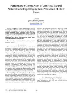
Fig. 15.
Measured performance of three-step and six-step PWM as function of load current: (a) THDi , (b) PF.
and ZSS injection can be equivalently implemented with space vector modulation with an appropriate distribution of the zero switching state vectors [17], [18]. IV. PERFORMANCE COMPARISON OF THREE-STEP AND SIX-STEP PWM Fig. 9(a) and (b) shows the measured steady-state waveforms of the phase currents ia , ib , and ic at nominal phase voltage of 120 Vrm s and for 2-kW load for the six-step and threestep PWM referenced to the negative envelope of the phase voltages, respectively. As can be seen in Fig. 9(a) and (b), for both the six-step and three-step PWM, the phase currents are distorted at segment transitions. However, these distortions are more pronounced for the six-step PWM. Consequently, the sixstep PWM has higher THD of phase currents and lower PF compared to the three-step PWM, as shown by the respective THD and PF measurements in Fig. 9(a) and (b). The phase-current distortions at segment transitions are primarily caused by the low-pass filtering and sampling of the inductor currents. In the three-step PWM, they are also affected by duty-cycle limitations. To explain the distortions in the phase currents caused by the low-pass filtering and sampling, Simulink simulations are employed. Specifically, simulations for the six-step and threestep PWM were performed for a decreased low-pass corner frequency of 20 kHz, instead of 92.5 kHz used in the experimental circuit, to amplify the effect of the low-pass filtering for the sake of a more clear explanation. The simulations were done without limiting the duty cycle, i.e., by allowing the full dutycycle range from zero to unity. The effect of a limited duty-cycle range is addressed by a separate set of simulations. The results of the simulations are presented in Fig. 11, which shows the sampled inductor-current waveforms before and after
the filtering. Specifically, in Fig. 11(c) and (e), the waveforms of the sampled filtered and an unfiltered inductor current for the six-step and three-step PWM are compared, respectively. The definition of the sampled filter inductor current Ixfs , xࢠ{a,b,c}, and the sampled unfiltered inductor current Ixs , xࢠ{a,b,c}, is given in Fig. 10. As it can be observed in Fig. 11(c) for the six-step PWM, in every 60°-segment, the sampled filtered inductor currents in two actively controlled phases are greater than the corresponding sampled unfiltered inductor currents. For example, in the highlighted 60°-segment in Fig. 11(c), Iafs > Ias and Icfs > Ics . To facilitate the understanding of this effect, the waveforms of the input phase voltages vx0 , xࢠ{a,b,c}, and inductor currents of phase “a”, i.e., ia , iaf , iafs , and ias in Fig. 11 (a)–(c) are zoomed in an around instant T1 , where sampled currents ias and iaf s have a negative slope, and instant T2 , where sampled currents ias and iafs have a positive slope, as shown in Fig. 12(a) and (b), respectively. As can be seen in Fig. 12, filtered inductor current iaf lags behind the inductor current ia . At the sampling instant (at the middle of a switching period, i.e., at the middle of the turn-on time of the upper switches), iaf > ia , and, therefore, the sampled filtered inductor current is greater than the sampled unfiltered inductor current, i.e., iafs > ias . The current controllers shape the sampled filtered-inductor currents to follow the reference currents so that iafs + ibfs + icfs = 0. At the same time, the sum of the three phase currents flowing in the circuit must be zero, i.e., the sum of the sampled unfiltered-inductor currents is also zero iaf + ibf + icf = 0. Therefore, if iafs > ias and icfs > ics , it follows that ibfs < ibs , as shown in Fig. 11(c). Since the current in the phase of a nonactive (passive) controller is greater than the actively controlled phase currents, at the 60°-segment transitions when the role of actively and nonactively controlled currents changes, the current of the phase transitioning to passive control and the phase
HUBER et al.: PERFORMANCE COMPARISON OF THREE-STEP AND SIX-STEP PWM
transitioning to active control exhibit step changes. These current changes at the 60°-segment transitions are primarily responsible for the increased current THD. At 120°-segment transitions of the three-step PWM, the difference between sampled filtered and sampled unfiltered inductor currents is significantly smaller than that at 60°-segment transitions of the six-step PWM, as it can be observed in Fig. 11(e). This effect can be explained by the reduced ripple in the inductor currents at the 120°-segment transitions, as shown by the zoomed in waveforms in Fig. 13. Consequently, the phase-current distortions at segment transitions due to the effect of low-pass filtering and sampling are less pronounced for three-step PWM than for six-step PWM. Simulation waveforms in Fig. 14 illustrate the effect of the duty-cycle limitations on the phase-current distortions at segment transitions for the three-step PWM. At 120°-segment transitions, without duty-cycle limitations, duty cycles dxn , xࢠ{a,b,c}, and inductor currents ix change without oscillations, as shown in Fig. 14(c) and (b), respectively. However, limitation of the maximum duty cycle below 1 causes a perturbation and results in duty-cycle oscillations at 120°-segment transitions, as shown in Fig. 14(e). Consequently, the inductor currents also exhibit oscillations at 120°-segment transitions as shown in Fig. 14(d), which results in increased THD. Specifically, with 5%–95% duty-cycle limits, the THD of the inductor currents increases by 1.48% compared to that without duty-cycle limits. The THD of inductor currents at different duty-cycle limits is presented in Table IV. It can be concluded from Table IV that in order to meet the THD < 5% requirement, the duty-cycle limits should be equal or less than 6%–94%. Finally, the measured THD of phase currents and PF in the 10%–100% load range are presented in Fig. 15(a) and (b), respectively. It should be noted that the THD and PF values in Fig. 15 are obtained as average values of the measured THD and PF of individual phases. As can be seen from Fig. 15, in the entire measured load range the three-step PWM exhibits lower THD and correspondingly higher PF compared to the sixstep PWM. The performance of the three-step is significantly better than that of the six-step PWM at lighter loads. For the experimental circuit with the three-step PWM, the measured THD of the input current was below 5% in the 50%–100% load range. V. SUMMARY In this paper, a three-step PWM method for an average current controlled three-phase six-switch boost PFC rectifier is proposed and its performance is compared to the conventional six-step PWM method. The steady-state duty cycles of the switches in the three-step PWM do not exhibit abrupt changes at the 120°-segment transitions, unlike the steady-state duty cycles of the switches in the six-step PWM, which change abruptly at the 60°-segment transitions. As a result, the three-step PWM induces smaller inputcurrent transients at the segment transitions, which improves its THD and PF performance and reduces its sensitivity to false
7271
segment detection. However, the three-step PWM, unlike the six-step PWM, is adversely affected by duty cycle limitations. Both the six-step and three-step PWMs can be implemented either with the phase-current controllers and an appropriate ZSS injection or with the phase–phase current controllers, which inherently include ZSS injection. Performance comparison of the three-step and six-step PWMs is done on a 3-kW prototype of the three-phase six-switch boost PFC rectifier. In the entire measured load range the three-step PWM exhibits lower THD and, correspondingly, higher PF compared to the six-step PWM. The performance of the three-step is significantly better than that of the six-step PWM at lighter loads. REFERENCES [1] J. W. Kolar and T. Friedli, “The essence of three-phase PFC rectifier systems—Part I,” IEEE Trans. Power Electron., vol. 28, no. 1, pp. 176– 198, Jan. 2013. [2] T. Friedli, M. Hartmann, and J. W. Kolar, “The essence of three-phase PFC rectifier systems—Part II,” IEEE Trans. Power Electron., vol. 29, no. 2, pp. 543–560, Jan. 2014. [3] M. P. Kazmierkowski and L. Malesani, “Current control techniques for three-phase voltage-source PWM converters: A survey,” IEEE Trans. Ind. Electron., vol. 45, no. 5, pp. 691–703, Oct. 1998. [4] M. Malinowski and M. P. Kazmierkowski, “Control of three-phase PWM rectifiers,” in Control in Power Electronics—Selected Problems. San Diego, CA, USA: Academic, 2002. [5] M. Hartmann, H. Ertl, and J. W. Kolar, “Current control of three-phase rectifier systems using three independent current controllers,” IEEE Trans. Power Electron., vol. 28, no. 8, pp. 3988–4000, Aug. 2013. [6] P. C. Todd, “U-134 UC3854 controlled power factor correction circuit design,” Unitrode Appl. Note, pp. 3–269–3–288, Sep. 1999. [7] M. Fu and Q. Chen, “A DSP based controller for power factor correction (PFC) in a rectifier circuit,” in Proc. Appl. Power Electron. Conf., Mar. 2001, pp. 144–149. [8] C. Qiao and K. M. Smedley, “A general three-phase PFC controller for rectifiers with a parallel-connected dual boost topology,” IEEE Trans. Power Electron., vol. 17, no. 6, pp. 925–934, Nov. 2002. [9] S. Hiti, D. Borojevi´c, R. Ambatipudi, R. Zhang, and Y. Jiang, “Average current control of three-phase PWM boost rectifier,” in Proc. 26th IEEE Annu. Rec. Power Electron. Spec. Conf., Jun. 1995, pp. 131–137. [10] K. Zhou and D. Wang, “Relationship between space-vector modulation and three-phase carrier-based PWM: A comprehensive analysis,” IEEE Trans. Ind. Electron., vol. 49, no. 1, pp. 186–196, Feb. 2002. [11] Powerex: PM50CLA120 Intelligent Power Modules, Data Sheets, 2009. [12] Texas Instruments: TMS320F2808 Digital Signal Processor, Data Manual, 2011. [13] L. Huber, M. Kumar, and M. M. Jovanovi´c, “Performance comparison of PI and P compensation in average-current-controlled three-phase six-switch boost PFC rectifier,” in Proc. Appl. Power Electron. Conf., Mar. 2014, pp. 935–942. [14] L. Huber, M. Kumar, and M. M. Jovanovi´c, “Performance comparison of three-step and six-step PWM in average-current-controlled threephase six-switch boost PFC rectifier,” IEEE Trans. Power Electron., vol. 30, no. 12, pp. 7123–7137, Dec. 2015. [15] D. M. Van de Sype, K. De Gusseme, A. P. M. Van den Bossche, and J. A. Melkebeek, “Duty-ratio feedforward for digitally controlled boost PFC converters,” IEEE Trans. Ind. Electron., vol. 52, no. 1, pp. 108–115, Feb. 2005. [16] Powerex: BP7B-L-Series IPM Interface Circuit Reference Design, Application Notes, 2009. [17] L. Huber, M. Kumar, and M. M. Jovanovi´c, “Implementation and performance comparison of five DSP-based control methods for three-phase six-switch boost PFC rectifier,” in Proc. Appl. Power Electron. Conf., Mar. 2015, pp. 101–108. [18] K. Zhou and D. Wang, “Relationship between space-vector modulation and three-phase carrier-based PWM: A comprehensive analysis,” IEEE Trans. Ind. Electron., vol. 49, no. 1, pp. 186–196, Feb. 2002.
7272
Laszlo Huber (M’86–SM’15) was born in Novi Sad, Yugoslavia, in 1953. He received the Dipl. Eng. degree from the University of Novi Sad, Novi Sad, Yugoslavia, the M.S. degree from the University of Niˇs, Niˇs, Yugoslavia, and the Ph.D. degree from the University of Novi Sad in 1977, 1983, and 1992, respectively, all in electrical engineering. From 1977 to 1992, he was an Instructor at the Institute for Power and Electronics, University of Novi Sad. In 1992, he was with the Virginia Power Electronics Center, Virginia Tech, Blacksburg, as a Visiting Professor. From 1993 to 1994, he was a Research Scientist with the Virginia Power Electronics Center. Since 1994, he has been a Senior Member of the R&D Staff at the Power Electronics Laboratory, Delta Products Corporation, Research Triangle Park, NC, USA, the Advanced R&D unit of Delta Electronics, Inc., Taiwan, one of the world’s largest manufacturers of power supplies. He has published more than 100 technical papers and holds eight U.S. patents. Dr. Huber received the IEEE Power Electronics Society Transactions Prize Paper Award for the best papers published in 2009 and 2013, and the Yugoslav Conference on Electronics, Telecommunication, Automation, and Nuclear Technique Best Paper Award in 1990. He is currently an Associate Editor of the IEEE TRANSACTIONS ON POWER ELECTRONICS.
IEEE TRANSACTIONS ON POWER ELECTRONICS, VOL. 31, NO. 10, OCTOBER 2016
Misha Kumar was born in New Delhi, Delhi, India, in 1987. She received the Bachelor of Technology degree in power-electrical engineering from Guru Gobind Singh Indraprastha University, Delhi, India, in 2009, the M.S.E.E degree from North Carolina State University (NCSU), Raleigh, NC, USA, in 2011. During her graduate studies, she worked as a Summer Research Assistant at FREEDM System Center, NCSU, Raleigh. Since August 2011, she has been a Member of R&D Staff at Delta Power Electronics Laboratory (DPEL), Delta Products Corporation, Research Triangle Park, NC. Her current research interests include analysis, modeling, simulation, and design of digital control of power converters especially single-phase, three-phase boost PFC rectifiers, and gradient power supplies for MRI applications.
Milan M. Jovanovi´c (S’85–M’88–SM’89–F’01) was born in Belgrade, Serbia. He received the Dipl. Ing. degree from the University of Belgrade, and the Ph.D. degree from Virginia Tech, Blacksburg, VA, USA, both in electrical engineering. He is currently the Senior Vice-President for R&D of Delta Products Corporation, the U.S. subsidiary of Delta Electronics, Inc., Taipei, Taiwan, one of the world’s largest manufacturers of power supplies. Dr. Jovanovi´c is a Member of the U.S. National Academy of Engineering.