in (23). Indicating with the transforms of we as- sume: (27). The coefficients and need to be ..... Dr. Vatalaro was a co-winner of the 1990 âPiero Fantiâ INTELSAT/.
322
IEEE TRANSACTIONS ON WIRELESS COMMUNICATIONS, VOL. 1, NO. 2, APRIL 2002
Performance Evaluation of a Network Synchronization Technique for CDMA Cellular Communications Franco Mazzenga, Francesco Vatalaro, Senior Member, IEEE, and Charles E. Wheatley, III, Fellow, IEEE
Abstract—For code-division multiple-access (CDMA) cellular communications synchronous operation offers significant advantages over asynchronous operation. This feature has been already included in second-generation systems, such as the CdmaOne based on the IS-95 standard. Nonetheless, synchronous operation does not seem to be assessed as a basic system option for third-generation systems. This is mainly due to the contrasted choice of having global positioning system (GPS) receivers located at any of the base transceiver stations (BTSs) to perform station synchronization. However, the existing CdmaOne interface permits time transfer between the various BTSs and a simple time difference measurement technique can provide an internal, network-based means for time synchronization of base stations clocks. This paper considers a recently proposed approach based on the pilot strength measurements message delivered by every mobile station (MS), combined with round trip delay measurements that BTSs perform on the MS transmissions. In this paper, we consider some possible algorithms to reduce time misalignments, and continuously phase-lock the clocks at different BTSs. Having developed an appropriate analytical/simulation approach, in the environment of a CDMA network, the paper evaluates and compares the performance of two suitable centralized architecture configurations, i.e., master–slave synchronization (MSS) and mutual synchronization (MUS). Both network architectures turn out to be applicable and provide suitable timing performance. Finally, the paper provides a preliminary discussion on some related issues, such as GPS avoidance, synchronization of BTSs inside buildings, tunnels, and subways and hybrid MSS/MUS synchronization network architectures. Index Terms—Centralized control, code division multiaccess, land mobile radio cellular systems, synchronization.
I. INTRODUCTION
F
OR code-division multiple-access (CDMA) cellular communications [1] synchronous operation offers significant advantages over asynchronous operation. Therefore, CDMA second-generation cellular systems such as the CdmaOne system [2], based on IS-95 specifications [3], require base transceiver stations (BTSs) to be synchronized to a few microseconds. The same feature has been included in the Cdma2000 proposal for third-generation (3G) systems. Manuscript received June 27, 2000; revised December 12, 2000; accepted April 4, 2001. The editor coordinating the review of this paper and approving it for publication is Q. Bi. This work was supported by Qualcomm Inc under grant Study Contract “Cdma2000 base stations synchronization”. F. Mazzenga and F. Vatalaro are with the Dipartimento di Ingegneria Elettronica, Università di Roma Tor Vergata, Rome, Italy (e-mail: mazzenga @ing.uniroma2.it). C. E. Wheatley, III, is with Qualcomm Inc., San Diego, CA 92121 USA. Publisher Item Identifier S 1536-1276(02)02094-9.
Nonetheless, synchronous operation does not seem to be assessed yet as a basic system option for 3G systems. Presently, global positioning system (GPS) receivers located at the BTSs are commonly used to perform BTSs synchronization. However, postal telephone and telegraph (PTT) administrations and/or mobile network operators may be reluctant to have a system based on GPS and/or on any other navigation systems out of their control. Two main concerns are generally put forward: GPS is under U.S. government control, and possible service limitations and installation difficulties may arise inside buildings, tunnels, subways, etc. For these reasons some proposed 3G CDMA systems have been designed to be asynchronous, and do not impose tight timing requirements to BTSs. However, such a drastic measure should be better avoided, not to lose the several benefits of synchronous CDMA such as: faster initial mobile acquisition, faster completion of handoffs, reduced mobile wake time when in idle-mode, increased reliability of common channels, and more options for accurate location-based services. Therefore, alternative strategies for BTSs synchronization should be studied and, possibly, implemented. To avoid, or at least reduce, dependence on GPS, it was observed that the existing CdmaOne interface (IS-95) permits time transfer between the various BTSs [4]. The measurement technique proposed in [4] adds an internal, network-based means for time synchronization of base stations clocks. Not only can this method alleviate the reliability requirement of the individual GPS receivers but, in principle, it can also eliminate the need for GPS timing at any BTSs. According to this new approach, the information contained in mobile generated messages, such as the pilot strength measurements message (PSMM), are combined with round trip delay (RTD) measurements that BTSs perform on mobile transmissions, in order to estimate time differences between any pair of BTSs. Centralized or decentralized algorithms can be used to reduce time misalignments, and continuously phase-lock the clocks at different BTSs. Having developed an appropriate analytical/simulation approach, in this paper we evaluate the performance of two centralized CDMA network synchronization architectures operating on the basis of the time differences computed through the technique introduced in [4]. The paper is organized as follows. In Section II, we first review and discuss the technique in [4] and then we summarize some applicable network synchronization concepts. In Section III, we identify suitable models for the BTSs clocks and we sketch a general clock timing correction procedure. Starting
1536-1276/02$17.00 © 2002 IEEE
MAZZENGA et al.: PERFORMANCE EVALUATION OF A NETWORK SYNCHRONIZATION TECHNIQUE
Fig. 1.
323
Timing transfer time-line.
from these models we describe and evaluate one synchronization algorithm operating with uniformly spaced time-offset samples extracted from the measurements provided by the technique in [4]. Then, Section IV evaluates the performance of the proposed synchronization procedures. In Section V, we provide a preliminary discussion on some related system level problems. Finally, in Section VI, we draw our conclusions. II. TIME OFFSET MEASUREMENTS In this section, we present a time transfer technique suitable for synchronization of BTSs and then we introduce the synchronization system architecture alternatives discussed in this paper.
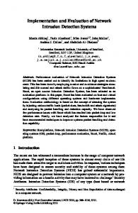
involved in soft-handoff.1 This estimation procedure enables timing transfer between two (or more) BTSs. It can be better understood looking at the timing diagram in Fig. 1. BTS(1) and BTS(2) measure the round trip time intervals indicated with and , respectively. We denote as and the propagation time to the MS from BTS(1) and from BTS(2), rethe “dead” time within the MS, spectively. We also denote as i.e., the time between reception and transmission at the MS of pilot 1. From the diagram in Fig. 1, we obtain the following set of equations:
(1)
A. Time Transfer Technique One CDMA key feature, present both in existing and in proposed systems, is soft-handoff (as known as soft-handover) [5]. During soft-handoff, a mobile station (MS) is simultaneously connected with multiple BTSs (normally two). The call processing procedure during soft-handoff for IS-95 is detailed in [3]. To initiate soft-handoff, a MS sends information on relative pilots strengths and relative arrival times in the PSMM. Information on pilots in the active set is transmitted in the PSMM (see [3]). Based on this information, soft-handoff is enabled to those links that will provide suitable diversity gain. The MS uses the first arriving pilot for demodulation as a time reference, since the parameters of other pilots are evaluated with respect to this time reference. In addition, a MS is normally required to align its uplink transmissions to within 1 s of this time reference, except when the reference pilot changes. The signal transmitted by the MS is transponded with respect to the reference pilot. Therefore, the reference BTS can estimate the propagation time by noting the time difference between the BTS transmission time and the time the mobile signal is received back at the BTS itself. This time difference is referred to as RTD. When soft-handoff is enabled the RTD can be suitably combined with the information in the PSMM to obtain the time difference estimate between the two (or more) BTSs
where is the time difference (offset) between the transmission is the delay of pilot 2 received instants of pilot 1 and pilot 2, at the mobile with respect to pilot 1, and is contained in the PSMM. Therefore, the time offset is given by (2) , Two remarks can now be useful. First, is independent of is unchanged if the round trip measureso the time offset ments are delayed or anticipated by a constant quantity. Second, the up-link transmission time is assumed to be identical to the down-link transmission time. This condition is valid in all practical cases, and is important so that a systematic error does not affect the measurement of . B. Applicable Network Synchronization Concepts Two different approaches are generally adopted for network synchronization [6]. The first is a hierarchical strategy known as master–slave synchronization (MSS). The second is a democratic strategy known as mutual synchronization (MUS). In a 1Actually the PSMM reports on all the pilots over a given threshold. This includes pilots in the neighbor as well as other sets. However, only the pilots in the active set can be used in the basic time transfer method because neighbor cells do not measure RTD.
324
IEEE TRANSACTIONS ON WIRELESS COMMUNICATIONS, VOL. 1, NO. 2, APRIL 2002
A. Clock Models Now we turn our attention to the clock parameters that should be extracted from the received time offset samples. To this aim we introduce a model to describe the clock of each BTS. We consider the normalized timing process of the clock [6] at the th BTS. It can be modeled as (3) is the number of BTSs, is the “free running” where is the control signal used to correct the clock. term, and In our case, the MSC provides the control signals to each BTS. The free running term is usually expressed as (4)
()
Fig. 2. Scheme of the assumed synchronization architecture—RT D i , with k ; are the round trip delays, and T is measured at the ith mobile terminal and is inserted in the PSMM to be broadcast to all visible BTSs.
=12
1
MSS approach, the clocks are all locked in phase and/or in frequency to a network master clock. The master clock must be highly accurate and reliable. In a MUS approach, there are no master clocks, and the network is partially or fully connected. Each individual clock adjusts its time so as to reduce the time offset between itself and a weighted average of the nearby, or all, other clocks. For the purpose of our study, we now introduce a reference centralized network architecture that can be conveniently used to implement both the MSS and the MUS strategies based on the time offset measurements obtained with the time transfer technique described above. We consider a certain number of BTSs connected to the same , mobile switching center (MSC). The MSC collects both , for any mobiles in soft-handoff and for any and pairs of BTSs involved in each soft-handoff procedure. Then, the MSC performs time offset calculations for each pair of BTSs in its set. Fig. 2 shows the architecture assumed for the purpose of our study. For simplicity, synchronization between BTSs belonging to different MSCs is not considered. In fact, we assume that no soft-handoff can take place between pairs of such BTSs. The problem of synchronization between BTSs belonging to different MSCs entails transfer of data between different MSCs. Therefore, we are only concerned here with the problem of providing synchronization within the set of BTSs associated to the same MSC. III. SYNCHRONIZATION TECHNIQUE In this section, we first introduce the clock models used in the rest of the paper, then, we provide one synchronization algorithm operating on the basis of the time offset measurements given in (2). Then, we analyze the characteristics of the measurement sample, along with those of noise and jitter.
is the initial phase, is the normalized frequency where is the phase error, is the normalized frequency drift, and noise term. Normalization is made with respect to the nominal frequency of the voltage controlled oscillator (VCO) that is assumed to be the same for all BTSs. For the following derivations the value of the nominal frequency is not important, and we assume that the nominal frequency is unitary. Therefore, in the following, we can simply refer to as the frequency error. Using (3) the time offset process between the th and th BTSs can be modeled as
(5) where
When the MSC evaluates the time offset between each pair of BTSs, e.g., between BTS( ) and BTS( ), we obtain noisy sam, i.e. ples of the random process noise
(6)
are measured at each soft-handoff time, using Samples of the technique in [4]. The noise term collects all possible effects, including thermal noise, quantization noise, etc. For simplicity, and without loss of generality, in the following we assume that for . B. Reference Clock Control Algorithm The main objective of a generic BTS clock control algorithm is to correct any timing phase differences and frequency errors, , , for , while no attempts are done i.e., . toward estimation and correction of the phase noise terms , the If we neglect the presence of the correction term and completely characterize the noisy parameters . A clock control procedure based on time offset process the measured time offset samples is now described. This algorithm is sufficiently general and has been assumed as the reference one for the purposes of our study.
MAZZENGA et al.: PERFORMANCE EVALUATION OF A NETWORK SYNCHRONIZATION TECHNIQUE
Fig. 3.
325
Scheme of the control procedure at the MSC.
Given a set of samples ,2 with , and an integer, we are requested to estimate , , and . The estimated values, , , and , or suitable combination of them, can be simultaneously transmitted to each BTS to perform phase, frequency and, possibly, frequency drift corrections. In practice, a mean square first-order linear interpolation can be used to extract the desired clock parameters, , so that the quadratic i.e., we can select estimates error functional
(7) in (7) indicates is minimum. The random variable the number of time offset samples measured in the th collection interval. in BTS( ) Now, the purpose of each correction signal is to alter the phase and the frequency of the th clock [e.g., , etc.]. So, after are characterized by upclock correction the processes and . Ideally, all updated values are dated values null for any and , so that the updated timing processes, neglecting phase noise, are perfectly aligned at any BTSs. and will be reestimated in the The offset values following fitting procedure cycle, based on a new set of sam, and so on. Fig. 3 illustrates the assumed clock ples, control procedure. The variable in Fig. 3 refers to the length of the observation interval during which time offset samples is a design parameter to are collected. The estimation rate be selected according to the expected average soft-handoff frequency, the degree of short and long term stability of the BTSs clocks, and the accuracy needed to estimate the clock parameters. Additionally, the estimation rate could be changed when steady-state conditions are reached. In Fig. 4, we illustrate the architecture of the proposed discrete-time clock control strategy. For simplicity of representation only time phase and frequency error clock corrections are illustrated. The two filters with imand are used to reduce noise pulse responses in the estimated parameters. The time dependence on the th collection interval of the estimated clock parameters has been 2Since t is the soft-handoff time between BTS(i) and BTS(k ) it should be . For simplicity of notation, we omit the superscript in the rest indicated as t of the paper.
Fig. 4.
Scheme of the clock control procedure at the MSC.
evidenced. The phase comparator in Fig. 4 processes the measurements obtained with the technique in [4] and then calculates the necessary clock parameters to perform clock corrections. In Fig. 4, a control commands generation unit (CCGU) is used to derive the suitable clock commands on the basis of the received synchronization data. In the MSS strategy, the MSC identifies a master BTS. For instance, the BTS with the highest number of connections with other BTSs can be selected. In a MSS strategy, phase and frequency corrections for each BTS need to be calculated with respect to the clock of the master BTS. Without loss of generality, we consider a case with four BTSs to better explain the procedure. Base stations are identified as BTS( ), with , and we arbitrarily assume BTS(1) as the master stabe the connection array between base stations, such tion. Let if a soft-handoff can occur between BTS( ) that and BTS( ) and, otherwise, zero. In our example, we assume an otherwise, zero. is sufficiently “well behaved” we can calculate , If , based on those frequency offset values diwhere rectly available from measurements. In our example, we cannot from measurements, while we can didirectly estimate and , therefore, we calculate as rectly extract follows:
The same approach is valid for evaluating where , either directly or indirectly. All these data are transmitted to the slave BTSs in the “correction” time interval (see Fig. 3) and the VCO time phase, frequency of the controlled BTS are correspondingly updated (see Fig. 4). In the MUS approach described in [6]–[8], the clock correction signal for each BTS is obtained by averaging the time-continuous time offset signals measured between the selected BTS and all the BTSs connected to it. If we use the model in (3)–(6) , and and we neglect the presence of the control signals noise, we have the averaged error signal (8)
326
IEEE TRANSACTIONS ON WIRELESS COMMUNICATIONS, VOL. 1, NO. 2, APRIL 2002
where
The coefficients
are given by if BTS( ) is connected to BTS( )
(9) otherwise, and when is the number of BTSs connected to BTS( ). Thus, in the and MUS case, the MSC calculates the estimated clock parameters ,and ,with ,and . Then it sends to BTS( ) their averages over the number of BTSs connected to BTS( ). In the following, we describe and evaluate some possible clock control algorithms that can be used with the measurements provided by the technique in [4]. According to [4], we obtain a set of non uniformly spaced time offset measurements for each pair of BTSs in the network. Now we intend to define a clock synchronization strategy based on uniformly time spaced quantities extracted from the non uniformly time spaced ones. A first method to build a uniformly time-discrete model is to consider only one representative time offset sample in each time interval . The simplest approach is to calculate the average of the measured time offsets for each collection interval (10) is the number of measured time differences between BTS( ) and BTS( ) in the th collection are the measurement times lying in the colinterval, and . In the following, we illustrate lection interval a clock control algorithm able to drive (10) around zero for each pair of BTSs in the network.
where
C. Analysis of the Discrete-Time Model Before deriving the clock control algorithm, in this section, we provide some alternative expressions for the averaged sample in (10). Neglecting the measurement noise, we have (11) th collection interval with and Substituting (11) into (10), we obtain In the
, we measure .
with
term
, i.e., (14)
The average is also calculated with respect to (14), we have
. Using (15)
affects As (15) shows, a frequency error proportional to . When are uniformly spaced in each collection is as in Fig. 5. time interval (uniform sampling), This figure shows that the time difference between BTS( ) and BTS( ) increases by (16) in each collection interval. When needs to be selected, it is for all the values of and where necessary that is the maximum allowed time difference between each s is usually assumed). If is pair of BTSs ( known, an upper bound can be achieved for the maximum value of to be selected in order to respect the tolerance specification. is related to the quality of the The maximum value of oscillators in the BTSs. In the presence of measurement noise, (15) can be rewritten as (17) accounts for the measurement noise in the time where offset samples. It is given by (18)
(12) Writing rewritten as
Fig. 5. Averaged samples as a function of time in the absence of noise and when a negative frequency error difference is considered.
(12) can be
(13) can be The random process decomposed as the sum of its average and a zero-mean random
is the noise in the time offset measured at . To a where is a white zero-mean first approximation, we assume that process and it is only related to the quantization error. In this , the variance of is case, conditioning on (19) is the variance of the quantization noise. The average where standard deviation of measurement noise can be achieved aver. aging (19) with respect to
MAZZENGA et al.: PERFORMANCE EVALUATION OF A NETWORK SYNCHRONIZATION TECHNIQUE
Fig. 7.
327
Discrete-time scheme of the proposed clock control procedure.
Thus, from (24) the NVCO transfer function is Fig. 6. Scheme of the proposed clock control procedure based on discrete-time phase locked loop (PLL).
(25) and denote the transforms of and , respectively. To drive to zero, we need to select so that the loop transfer function the filter
where
D. Control Algorithms In this section, we illustrate a synchronization algorithm to in (10) around zero for drive the average time offset each pair of BTSs in the network. We consider a generic pair of BTSs in the network, say BTS( ) and BTS( ), the latter being the controlled BTS. The principle scheme of the proposed control procedure is illustrated in Fig. 6. After time phase correction the clock signal of the controlled BTS is for
(26) (e.g., see [9] and [10]). We contains at least two zeros in the transforms of in (23). indicated as the transforms of we asIndicating with sume:
(20)
is the time phase correction term applied up to where in the clock of the controlled BTS. Therefore, the time time offset between BTS( ) and BTS( ) is (21) The “phase comparator” in Fig. 6 performs time averaging of as output. the measured time offset samples and gives Using (17), the average time offset is
(22) . To drive where we indicated toward zero, we vary . The clock control procedure in Fig. 6 operates as follows. The time phase of the VCO located in the controlled BTS is varied by a step proportional which is obtained at the output of the discrete-time to in Fig. 6. The process of varying the phase of the filter VCO in the controlled BTS can be modeled with the numerical VCO (NVCO) in the time-discrete scheme of Fig. 7, which is obtained from the scheme in Fig. 6. To obtain the scheme in Fig. 7, we assumed (23) The NVCO performs a discrete-time integration, i.e., (24)
(27) and need to be selected in order to have The coefficients a stable and a low noise loop [10]. The above procedure can be directly applied to the MSS case to control each pair of BTSs in the network. The procedure can also be used in the case of MUS, provided that the average time sample is (28) where in (9).
is the number of BTSs in the network and
is given
IV. RESULTS OF THE ANALYSIS In this section, we provide some results to illustrate the effectiveness of the proposed technique. First, some simulation results are shown to evidence the convergence behavior of the procedure. Then, some statistical parameters are reported. To obtain the results illustrated in the following sections, we simulated the normalized time phase processes in (20) for each BTS in the network and the clock control procedure in Section III-D was applied. Time differences between two handoff events were assumed to be random with exponential statistic with handoff frequency . Time differences were assumed to be statistically independent. Finally, a uniform measurement noise with stanns was considered. This value was obdard deviation tained from the experiments described in [4].
328
IEEE TRANSACTIONS ON WIRELESS COMMUNICATIONS, VOL. 1, NO. 2, APRIL 2002
Fig. 8. Time difference between each pair of BTSs as a function of the handover instants, H H 0:5, M = 6. (a) MSS case. (b) MUS case.
=
=
Simulation results were provided for both the MSS case and the MUS case. A. Simulation Results , an observation time , and an average time between soft-handoff s. Furthermore, the frequency errors are for each randomly generated in the interval BTS( ). In Fig. 8(a) and (b), we illustrate the time difference for each pair of BTSs in the network as a function of the soft-handoff times. The MSS case and the MUS case have been BTSs in the network were considered. analyzed and In the MUS case, we always assume that the BTSs are fully connected. This is not a limitation for the applicability of the proposed control technique. The same initialization parameters (frequency errors and initial time differences) were used in the MSS case and in the MUS case. We assume
Fig. 9. Time difference between each pair of BTSs as a function of the handover instants, H = 0:2; H = 0:8. (a) MSS case. (b) MUS case.
In our examples, the plots cover 7 10 s (about one week). This is a very long time, however, soft-handoff from a given mobile generally happen fast than one per minute, and any given BTS sees more than one mobile. This could reduce the pull-in time by a factor of ten. In Fig. 9(a) and (b), we illustrate the time difference behavior for each pair of BTSs in the network as a function of the softBTSs and , . handoff times for BoththeMSS caseandtheMUScaseareconsidered.Asexpected, and and convergence time also depends on the values of rapidlyincreasesif and areselectedsothattheloop transfer function has a pole near the unit circle. Thus, proper (adaptive) selectionof and can helpinreducingthelong pull-intime that may be experienced in the case of low handoff frequency (such as in rural areas served by macrocells with large radius). in (15) on Finally, to illustrate the effect of random term the selected closed loop clock control strategy, in Fig. 10(a) and
MAZZENGA et al.: PERFORMANCE EVALUATION OF A NETWORK SYNCHRONIZATION TECHNIQUE
329
Fig. 11. Standard deviation of the sequence at the output of the phase comparator as a function of the number of BTSs in the network, H = H = 0:5, MSS case and MUS case.
Averaged sample as a function of the time collection interval = = 0 5 MSS case. (a) With measurement noise. (b) No measurement noise.
Fig. 10. H
H
:
(b), we show the average time sample measured at the output of the phase comparator with and without measurement noise. The BTSs. From Fig. 10, it MSS case was considered and can be observed that even in the absence of measurement noise the average sample still shows very small oscillations about zero. As expected, from simulation it was further observed that in the absence of measurement noise, residual oscillations completely disappear when uniformly spaced time sample measurements are taken. A similar behavior was observed in the MUS case. B. Statistical Results In Fig. 11, we provide the standard deviation of the sequence at the output of the phase comparator in Fig. 6. To obtain the standard deviation in Fig. 11 a Monte Carlo simulation was performed. At each iteration the initial time phases and the fre-
quency errors for each BTS were randomly generated and we evaluated the variance of the sequence at the output of the phase comparator in steady state conditions. Standard deviation was obtained as the square root of the mean variance. As expected, in the MSS case the standard deviation does not change with the number of BTSs in the network. On the contrary, due to the averaging effect, in the MUS case the standard deviation rapidly decreases with the number of BTSs. Finally, we observe that the proposed algorithm is not able to in each colcompensate for the time phase offset due to lection time interval. This is not significant if the collection time is fulinterval is selected so that the condition is such that , to a first attempt filled. When we can lower . In this case, the average number of available time offset measurements may be considerably reduced and estimated parameters may be affected by large errors. A first alternative, not reasonably implemented, is to update the clocks whenever there are measurements. This would make a variable. Keeping constant is maybe the right choice, and adaptively reducing it may be desirable. In this case, when timing , or is too small data are not available, i.e., for the average time sample in (10) to have a low measurement noise, no corrections are applied or a correction in the previous step is first weighted and subsequently reapplied. Another alterand to suitably native to varying , consists in estimating correct the frequency error at each BTS. In this case, we need to resort to the algorithm in Section III. V. RELATED SYSTEM-LEVEL ISSUES Some specific problems at system level may require additional investigations, to optimally implement a selected synchronization strategy based on the time transfer technique introduced in [4]. Three of them are now preliminarily discussed: GPS avoidance, synchronization of BTSs inside buildings, tunnels, and subways and, finally, hybrid synchronization network architectures.
330
IEEE TRANSACTIONS ON WIRELESS COMMUNICATIONS, VOL. 1, NO. 2, APRIL 2002
GPS avoidance was one main motivation for this study. As stated in Section I, it would be desirable avoiding usage of external navigation systems. However, the proposed network synchronization algorithms properly operate if the BTSs clocks start in a quasi-synchronous state, i.e., if time offsets between the BTSs do not exceed a threshold above which it may be difficult to perform soft-handoff. In addition, when the synchronization procedure is started, it may be necessary to ensure that time offset overshoots do not exceed a given threshold (e.g., 10 s, or so). In this case, BTSs cannot be considered synchronous and, possibly, soft-handoff may not be enabled, too. Should the proposed synchronization procedure be used as the basic synchronization method for the network, a suitable method to drive the BTSs toward steady-state need to be studied. Obviously, a possibility is to adopt a GPS receiver for a short time interval at each start of network operations. However, by doing so autonomy of the CDMA network with respect to GPS, as some network operators request, is not achieved. Assuming that at least one MS is always available (e.g., appropriately located on purpose),3 a base station can force this MS to transmit the PSMM, or equivalent message. This station can now measure a RTD. However, to apply the time transfer technique in [4], it is necessary that the same BTS asks for another BTS in the active set of the MS to perform another RTD measurement, and this would imply a preventive exchange of information between both BTSs. Notice that if this procedure is available, in principle the technique would be independent of the soft-handoff frequency. Therefore, we can expect that GPS is no longer needed, and that the network could be able to maintain its synchronization, after an initial alignment procedure (operator assisted). The second point to be discussed concerns BTSs located in special conditions such as inside buildings, tunnels, and subways where CDMA networks can face difficulties in synchronizing BTSs. In fact, in these cases it may be difficult to install GPS antennas. In principle, the time transfer technique offers an effective means to solve this problem, conditioned on the average soft-handoff frequency is sufficiently large (value to be determined as a function of network conditions). The positioning of GPS antennas inside buildings is a topic of great interest. However, it is out of the scope of the paper to illustrate the available market products that can be used to solve this problem. The third and last comment regards the synchronization architecture of a large network (or, said differently, of a fullydeployed network of BTSs). When the number of BTSs involved in the network synchronization procedure is large, hybrid MSS/MUS strategies could be preferred. The proposed algorithms are sufficiently flexible to accommodate for hybrid synchronization solutions. If a single MSC serves all the base stations under consideration, the first hybrid architecture that can be easily implemented is composed of a principal set of mutually synchronized BTSs. To each MUS-synchronized base station we can associate a subset of secondary BTSs. The clock of each secondary BTS is, therefore, slaved to the (average) clock of the mutually synchronized principal base stations set. 3This
could be a function provided at a specific BTS, or at all of them.
A hybrid MSS/MUS architecture may be appropriate, as it promises to combine the advantages of both the master–slave and the MUS approaches. Additional considerations should be made to establish criteria to apportion base stations between the two sets of primary and secondary BTSs, ensuring both stability and good steady-state performance. A stability analysis for both the MSS and the MUS techniques has been reported in [11]. For the hybrid network case, a more thorough consideration of network performance in transient conditions may also be advisable. VI. CONCLUSION Our study aimed at evaluating performance of a time transfer technique recently proposed in the literature [4]. This new technique relies upon autonomous means for time synchronization of base stations clocks in a CDMA network, without need to resorting, in principle, to external time references, such as the GPS at any BTSs. According to the technique in [4], the information contained in mobile-generated messages, such as the PSMM, is combined with round-trip delay measurements. By appropriate processing, the time offset information between pairs of base stations can be extracted. Both centralized and decentralized algorithms can be used to reduce time misalignments between different BTSs. In our study, we investigated on centralized approaches performed at the MSC. Our investigations pointed out that different network architecture configurations appear to be feasible to implement a network synchronization procedure based on the technique in [4]. The hierarchical MSS approach and the democratic MUS approach have been considered here. Both turn out to be applicable and provide suitable timing performance. In the present case, a main difference with respect to the MSS and MUS architectures previously analyzed in the literature consists of the randomness of timing data availability. This implied the need to devise an appropriate analysis approach, and to resort to computer simulation for performance evaluation. The flexibility of the MSS and MUS procedures is another important aspect to be considered. In fact, the CDMA network can evolve and the number of BTSs can considerably increase during its lifetime. From our studies, MUS performs better than MSS but it is less flexible, especially if we need to insert an additional BTS in the network. The computational complexity of the MUS strategy is higher than that of MSS. However, due to averaging performed in the MUS case, more accurate results with respect to the MSS strategy can be achieved. In fact, when the noise contributions on the measurements can be considered statistically independent (as it is the case), averaging allows to considerably reduce the power of the overall noise term. Finally, the paper provided a preliminary discussion on some related issues, such as GPS avoidance, synchronization of BTSs inside buildings, tunnels, and subways, and hybrid MSS/MUS network architecture configurations. APPENDIX JITTER ANALYSIS The last term in (15) can be seen as a “jitter” with respect . Its characteristo the time position
MAZZENGA et al.: PERFORMANCE EVALUATION OF A NETWORK SYNCHRONIZATION TECHNIQUE
331
measurements. In this case, from simulation we conjectured that (30) Using (30), (17) can be rewritten as
(31) Although it is not easy to calculate the first and second-order in (14), two simple upper bounds can be found moments of for the mean and the variance. In particular, for relatively large , we have values of (32) and (33) To derive the two upper bounds in (32) and (33), we used (29) as and we expressed
(34)
Fig. 12. (a) Simulated normalized first-order moment of the non uniform samples noise and its upper bound. (b) Ratio between the upper bound on the variance and the simulated variance.
tics depend on the handoff statistics. In general, the statistical characterization of this term may be hardly achieved. Assuming handoff statistics, in this section, we derive an upper bound on the variance of the jitter term in (15) or in (17). can be obtained as a cumulative sum of By definition, random variables, i.e.,
were assumed to be statistically indeThe random variables pendent and unconstrained. To obtain (32) and (33) we further is a Poisson random variable with average assumed that . value In Fig. 12(a) and (b), we show the first-order moment obtained from simulation and from the upper bounds in (32) and the ratio between the upper bound in (33) and the simulated variance. From Fig. 12(b), it can be noted that the upper bound in (33) is always about four times larger than the simulated variance. ACKNOWLEDGMENT The authors wish to thank Prof. A. J. Viterbi for suggesting the study and for continuous advice. They also thank the anonymous reviewers for their comments that led to sensible improvement of the paper. REFERENCES
(29)
are independent and and for simplicity, we consider that . identically distributed in each time interval For this reason in the following, we omit the dependence on . are exponentially distributed, i.e., We assume that , and with the average time between two soft-handoffs or, equivalently, two consecutive time difference
[1] A. J. Viterbi, Principles of Spread Spectrum Communication. Reading, MA: Addison-Wesley, 1995. [2] K. S. Gilhousen, I. M. Jacobs, R. Padovani, A. J. Viterbi, L. A. Weaver, Jr., and C. E. Wheatley, III, “On the capacity of a cellular CDMA system,” IEEE Trans. Veh. Technol., vol. 40, pp. 303–312, May 1991. [3] TIA/EIA/IS-95, “Mobile station–base station compatibility standard for dual-mode wideband spread spectrum cellular system,” Telecommunication Industry Association, July 1993. [4] C. E. Wheatley, III, “Self synchronizing a CDMA cellular network,” Microwave J., vol. 42, pp. 320–328, May 1999. [5] A. J. Viterbi, A. M. Viterbi, K. S Gilhousen, and E. Zehavi, “Soft handoff extends CDMA cell coverage and increases reverse link capacity,” IEEE J. Select. Areas Commun., vol. 12, pp. 1281–1288, Oct. 1994.
332
IEEE TRANSACTIONS ON WIRELESS COMMUNICATIONS, VOL. 1, NO. 2, APRIL 2002
[6] W. C. Lindsey, F. Ghazvinian, W. C. Hagmann, and K. Dessouky, “Network synchronization,” Proc. IEEE, vol. 73, pp. 1445–1467, Oct. 1995. [7] J. H. Chen and W. C. Lindsey, “Network frequency synchronization—Part I,” in Proc. MILCOM-98, Boston, MA, Oct. 18–21, pp. 973–975. , “Network frequency synchronization—Part II,” in Proc. IEEE [8] Globecom-98, Sydney, Australia, Nov. 8–12, pp. 3086–3090. [9] A. J. Viterbi, Principles of Coherent Communications. New York: McGraw Hill, 1966. [10] W. C. Lindsey and C. M. Chie, “A survey of digital-phase locked loops,” Proc. IEEE, vol. 69, pp. 410–431, Apr. 1981. [11] F. Mazzenga and F. Vatalaro, “Performance evaluation of a network synchronization technique for IS-95 and cdma2000,” Qualcomm Report, 1999.
Franco Mazzenga received the Dr.Ing. degree in electronics engineering cum laude from the University of Rome Tor Vergata, Rome, Italy. He received the Ph.D. degree in telecommunications from the University of Rome Tor Vergata, discussing a thesis on “Parameter estimation of cyclostationary processes for multiuser spread spectrum systems.” In 1993–1994, he was with Fondazione Ugo Bordoni (FUB), involved in radio propagation at millimeter waves. From 1998 to 2000, he was a researcher at the Consorzio di Ricerca in Telecomunicazioni (CoRiTeL), Rome, Italy. Presently, he is a Researcher at the Electronic Engineering Department of the University of Rome Tor Vergata. His main interests are in statistical signal processing, multiple access radio techniques with emphasis on UMTS, and in estimation theory. Dr. Mazzenga was awarded the prize for the 40th year of the FUB, Rome, Italy for his thesis.
Francesco Vatalaro (M’85–SM’91) received the Dr.Ing. degree in electronics engineering from the University of Bologna, Italy, in 1977. He was with Fondazione Ugo Bordoni, FACE Standard, and Selenia Spazio, Italy. In 1987, he became an Associate Professor of Radio Systems at the University of Roma Tor Vergata, Italy, where he is presently a Full Professor. In 1998, he was a Visiting Professor at the University of Southern California, Los Angeles, and in 2000 was a Visiting Professor at University of California, Los Angeles (UCLA). Since 1985, he collaborated in and promoted several satellite communications projects within national Italian and European programmes. He is the author of about 100 research papers published in international journals and conference proceedings. His research interests include mobile and personal communications, satellite communications, spread spectrum systems, and multiple access systems. Dr. Vatalaro was a co-winner of the 1990 “Piero Fanti” INTELSAT/ Telespazio international prize. He is a member of the Editorial Board of the Int. J. of Satellite Communications, New York; Wiley. He is the Chairman of the IEEE Joint Vehicular Technology/Communications Society Italy Chapter, and is a member of several Scientific Committees in Italy.
Charles E. Wheatley, III (F’99) received the B.S. degree in physics from the California Institute of Technology, Pasadena, in 1956, and the M.S. and Ph.D. degrees in electrical engineering from the University of Southern California, Los Angeles, in 1958 and 1972, respectively. He has been involved with spread spectrum systems for over 36 years, initially working with frequency hopping systems for military applications at North American Aviation, later Rockwell International. From 1973 to 1981, he contributed to the GPS program on various terminal designs and also on GPSs spaceborne Rubidium Frequency Standard. In 1982, he moved to Linkabit Corporation, where he was involved primarily with the Milstar program, concentrating on radio frequency (RF) and system issues. He joined QUALCOMM Inc., San Diego, CA, in 1987, and is now Senior Vice President-Technology, concentrating on RF hardware design, system design, field-testing, and standards development. He has been working on various aspects of CDMA as applied to cellular/personal communications since its inception in 1989. He holds over 45 patents on various techniques and devices, all related to the field of communications.