International Journal of Scientific & Engineering Research, Volume 4, Issue 5, May-2013 ISSN 2229-5518
44
Performance Evaluation of Custom Power Devices in Power Distribution Networks to Power Quality Improvement: A Review Mahmoud zadehbagheri, Naziha Ahmad Azli, Askar bagherinasab, Shahrin bin Md Ayob Abstract—Power distribution networks are considered the main link between power industry and consumers and they are exposed to public judgment and evaluation more than any other section. Thus, it is essential to study power quality in distribution section. On the other hand, power distribution networks have always been exposed to traditional factors such as voltage sag, voltage swell, harmonics and capacitor switching which destruct sinusoidal waveforms and decrease power quality as well as network reliability. These are the abnormalities which are imposed to the networks by the consumers resulting in bad effects on other consumers and the network equipment. Thus, power suppliers are committed to provide the consumers with a reliable power of acceptable quality. These goals are achieved by applying power electronic devices, called Custom Power devices, in power distribution networks to solve the problem of abnormalities which disturb power quality. The present study tries to introduce and compare different types of Custom Power Devices and explain their application and the simulation results show the role of these devices in power quality enhancement. Index Terms— Custom Power Devices, Distribution Networks, Power Quality, Voltage Abnormalities.
—————————— ——————————
1 INTRODUCTION
P
ower quality started to gain high importance for power supply companies and low voltage consumers since the late 1980s. In this regard, the power distribution companies tried to improve power quality following the consumers' requests. The reasons behind the increasing attention on this issue can be as follows: If a component fails, severe consequence will emerge due to the complex interconnection of the systems- significant increase of harmonics in power systems power supplier companies pay more attention to power quality due to increasing knowledge of the consumers about power quality issues- higher sensitivity of the existing electrical equipment against the different kinds of disturbances manifested in power distribution networks[1,2,7].Today,electrical equipment producers present their products based on the power quality level. Based on the available standards in this regard, development of power electronic devices and the offered models to compensate for the variations in power distribution networks aim to provide the highest level of power quality for the consumers. These power quality equipment’s are the power electronics devices which are connected together either in series or shunt and their performance is monitored by an intelligent digital control system [3,4,9].
IJSER
————————————————
Mahmoud Zadehbagheri is with the Universiti Teknologi Malaysia, Faculty of Electrical Engineering, 81310 Skudai , Johor, Malaysia .(
[email protected]) Naziha Ahmad Azli is with the Universiti Teknologi Malaysia, Faculty of Electrical Engineering, 81310 Skudai, Johor, Malaysia. (
[email protected]). Askar Bagherinasab is with the Universiti Teknologi Malaysia, Faculty of Electrical Engineering, 81310 Skudai, Johor, Malaysia. (
[email protected]). Shahrin bin Md Ayob is with the Universiti Teknologi Malaysia,Faculty of Electrical Engineering , 81310 Skudai, Johor, Malaysia. (shahrin @fke.utm.my).
2 POWER QUALITY
Power quality is a term used to describe the rate of voltage quality in A.C power systems [7,8]. An ideal status for a power network is achieved when a balanced/undistorted threephase voltage with a sinusoidal waveform and constant magnitude and frequency is delivered and any deviation from the ideal status is regarded as weakness in power quality. Electricity consumers evaluate power quality based on its influence on the operation of their equipment and devices [2]. Since sensitivity to power quality disturbances varies from one device to another, different consumers show different perspectives towards the delivered power quality. For example, variation in voltage magnitude may not disrupt operation of a heater. However, emergence of this phenomenon in any lighting device may lead to variation in the amount of produced light resulting in eyestrain. From the perspective of one consumer, voltage variation is not considered a noticeable disruption whereas another consumer may consider this phenomenon as an important disturbance in power quality. Therefore, it is difficult to identify a unanimous criterion for power quality. Recently, extensive efforts have been made by other organizations such as International Electro technical commission (IEC) and Institute of Electrical and Electronics Engineers (IEEE) to identify and classify various power quality disturbances and set a limit for each of them. In this study, it is tried to introduce some methods applied to mitigate various types of power quality disturbances. Therefore, this paper presents a comprehensive survey of custom power devices for mitigation of Power quality problems. [5,6].
2.1An overview of Power quality Improvement Methods There are some long-established methods to mitigate power quality disturbances. Since voltage sags and interruptions have been regarded as the most widespread type of power quality disturbance in the past, various methods have been proposed to confront these two phenomena , Motor-generator
IJSER © 2013 http://www.ijser.org
International Journal of Scientific & Engineering Research, Volume 4, Issue 5, May-2013 ISSN 2229-5518
sets (to confront interruptions) and Ferro resonance Transformers (to confront voltage sags of large loads) are among these methods [10,11]. Devices such as Load Tap Changing Transformers, line voltage drop compensators and shunt capacitors are common to solve the problem of long-term voltage changes. Surge arrestors are applied to protect against transient overvoltage’s . Passive filters are used to reduce the harmonic distortion level of current flow and network voltage. Technology advancement in power electronics has played a significant role in the emergence and evolution of power quality improvement devices .The following parts of the present study introduce some of these devices and explain how they operate[5,6,7].
3
CUSTOM POWER DEVICES
Applying power electronic devices to improve energy transmission systems under the concept of Flexible AC transmission systems (FACTS) is almost a widespread method. However, applying these devices in distribution systems has not been considered until recent years due to the expansion of distribution systems and absence of need to these devices. In the last two decades, high power quality has become essential due to significant expansion in the use of electronic devices at all levels of consumers .(industrial, commercial and domestic) and high sensitivity of these devices to various types of power abnormalities. One of the power quality improvement solutions is using FACTS devices in distribution systems with different application and controlling strategy which is proposed under the term Custom Power. In fact, reliability and power quality are the goals considered in distribution networks and these goals are achieved through Custom Power devices [12,13]. Applying custom power devices is one of the two ways for power improvement in shops, offices and houses .The other way is for the companies that develop the products being consumed in the distribution networks to improve their products. There are many reasons to use custom power devices among which the following reasons can be pointed out [14]: most factors that damage power and influence sensitive loads are derived from the system itself. If the consumers' power quality issues are solved by improving performance of power production sources (distribution networks), the former can be given better services. Finally improving power quality through using custom power devices costs less than solving the problems of one or more specific customers. Fig.1 illustrates the application of FACTS devices as well as custom power devices [15,30].
45
4 GENERAL CLASSIFICATION OF CUSTOM POWER DEVICES Generally, custom power devices fall into two main categories as shown in Fig. 2 . The first category contains those devices that do not need DC energy storage sources and are mainly applied as static keys in the system and play the role of ordinary circuit breakers and advantage of these switches than conventional mechanical switches is their high switching speed. Generally speaking, these devices are subcategories of solid state breakers(SSBs). Among these devices, solid state transfer switches(SSTS) are the most widelyused and are usually located to back up sensitive loads and generally according to type and sensitivity of load , in addition to primary feeder , secondary feeder is also required. [15]. Unlike SSBs, the devices that need DC energy storage sources have complicated power and control circuits. Moreover, these devices may be employed in applications such as compensating active and reactive power, eliminating harmonics and compensating for unbalanced voltage etc. These devices can undertake different roles based on their applications. For example, these devices can be applied as an active power filter for removing harmonics. This type of custom power devices falls into three groups: shunt( Distribution Static Compensator), series (Dynamic Voltage Restorer) and series-shunt(Unified Power Quality Conditioner). The following subsections elaborate on each of the three groups of custom power devices [16,31].
IJSER
Fig. 1 Application location of FACTS and Custom Power devices
Fig. 2 Types and configuration of Custom Power Device
4.1 Distribution Static Compensator (D-STATCOM) Compensating for reactive power in a distribution network plays a crucial role in the power quality improvement, power factor correction and maintaining constant voltage distribution. Among the various existing conditioners, voltage controllers for voltage source converters quickly respond to reactive power demands. Thus, they are used for power factor correction and voltage regulation. Distribution static compensator (D-Statcom) is a type of VSC-based controllers regarded as an appropriate alternative for Static VAR Compensator( SVC) and they can take the capacitive reactive power current from the power system to produce reactive power [7,11]. D-STATCOM is used to compensate for power quality disturbances such as unbalanced voltage, voltage drop and voltage variations that occur in a millisecond. In such a short time, D-STATCOM can inject active and reactive power into the system for sensitive loads compensation.Active power injection must be conducted through an energy storage system.
IJSER © 2013 http://www.ijser.org
International Journal of Scientific & Engineering Research, Volume 4, Issue 5, May-2013 ISSN 2229-5518
D-STATCOM can operate like a synchronous voltage source which has variable phase and magnitude. In this case, the terminal voltage is controlled leading to power factor correction. In addition, this device can be used as an active filter to eliminate current harmonic [17,18]. When D-STATCOM is used along with a SSB and an energy storage source, it operates like an uninterruptable power supply (UPS) for short-term interruptions. Moreover, D-STATCOM can be used as an efficient device for voltage flicker compensation [10,11]. Fig. 3 illustrates the main function of a D-STATCOM. These functions are harmonic compensation for load, negative sequence current and reactive current. D-STATCOM operates like a synchronous condenser without mechanical inertia and controls fluctuations easily and quickly using its power electronics properties. As the D-STATCOM operates, line parameters are supervised permanently and compared with the optimal signal strength. Then, the required current and voltage are created to eliminate disturbances. Thus, this device does not allow the load-created disturbances into the system.
46
S DVR Sl Vinject
(1)
In which SDVR and Sl are the MVA ratings of DVR and load and Vinject is the injected voltage in pu. For example, a DVR with the capacity of approximately 50% for sensitive load keeps load voltage for 98% of load losses based on the distribution system in 0.9 per unit. Another aspect to be considered in a DVR is its ability in injecting the required energy into the distribution system. Fig. 4 illustrates the power circuit of a DVR. It consists of four main parts: mainly a voltage source inverter (VSI) , an injection transformer, a passive filter and an energy storage [22].
Fig. 4 Actual schemes of a DVR
IJSER
Fig. 3 Main Functions of D-STATCOM
It is worth mentioning that STATCOM was used for the first time in sawmills in England, Colombia and Canada to control flickers caused by large induction motors. D-STATCOM has the rating of 2 MVA and a load of 2.6 MVA with the power factor of 0.85. Voltage variations in these factories were caused by device current difference while cutting the logs. These current flow changes cause voltage variation at the point of common coupling( PCC). Using D-STATCOM eliminates these voltage variations [19,20,21,35].
4.2 Dynamic Voltage Restorer (DVR) Dynamic voltage restorer is a powerful electronic device that can compensate for voltage sags and voltage swells caused by disturbances and is structurally similar to D-STATCOM and consists of three single-phase inverters and a DC bus. However, a DVR's transformers are connected to a distribution line in series and controls magnitude and voltage phase of the two sides of load by injecting voltage into the network in a millisecond. By using a D-STATCOM, it is aimed to protect sensitive loads against negative effects of disturbing loads. However, using a DVR aims to protect sensitive loads against disturbances of the system. The main application of the DVR is to improve voltage sag and voltage sinking through three-phase voltage injection into the distribution network voltage in series or synchronously. In different applications and capacities, DVR is used with nominal capacity of 2-4 MVA to inject voltage of 0.3-0.5 per unit in 300-500 milliseconds. The nominal capacity of a DVR is calculated in the following way:
Designing the control system in a DVR is of high importance since it determines its response speed and how it can compensate for voltage sag and voltage swell. Control circuits are used to analyze control signal timing parameters such as magnitude, frequency and phase shift that are injected by the DVR. The injected voltage is supplied based on the control signal and by means of the existing inverters on the power circuit. A DVR can determine the amount of voltage sag or voltage swell by measuring the network's three-phase voltage and comparing it with the reference voltage and then exerts the appropriate command signal into the power electronics converter. An AC/DC converter is a voltage-source-type converter that produces the required voltage and injects it into the network through a series transformer. In the case that only short-term voltage variations are considered, using a DC capacitor as an energy restoration component suffices. However, a power supply must be used on the side of the DC converter if permanent voltage regulation and voltage distortion compensation. Fig.5 is a simple illustration of a DVR on the distribution network[23,24,25].
IJSER © 2013 http://www.ijser.org
Fig. 5 an overview of a DVR and its Operation
International Journal of Scientific & Engineering Research, Volume 4, Issue 5, May-2013 ISSN 2229-5518
4.3 Unified Power Quality Conditioner (UPQC) A UPQC is the most comprehensive system for power quality improvement of distribution networks suggested so far. Structurally, UPQC is a combination of a D-STATCOM and a DVR that are common in a short circuit. As illustrated in Fig. 6 .In fact, a UPQC comprises of two PWM-controlled converters that use one DC bus jointly.Two parameters of current and voltage are used as reference on the control circuit. In this structure, the parallel branch is responsible for load current harmonic compensation, reactive power compensation, power factor correction and no-load current correction. In contrast, the series branch is responsible for compensating for harmonic components of network voltage, correcting three-phase voltage unbalance, compensating for voltage sag and voltage swell, voltage flicker compensation and damping harmonic fluctuations between load and network [26,27,28,32].
47
Adding a parallel active filter on the load side the UPQC results in universal power quality conditioning system (UPQS). Consequently, UPQS is derived from UPQC. The main goal of a UPQS is compensating for source voltage and load current faults such as line voltage sag and voltage swell, temporary interruptions, unbalance, flicker, reactive distortion and unbalanced current. Fig.8 illustrates an overview of a UPQS used for power quality improvement and it contains a harmonic generating load with parallel connection(diode and thyristor) and sensitive load. The feeder also has harmonic distortions. The p-q theory is used in controlling both the series and parallel components [28,29,33].
IJSER
Fig.8 Overview of UPQS
5
Fig.6 Schematic of UPQC
5.1 D-STATCOM
Fig.7 shows a combination of series and parallel compensation in which network voltage harmonic is represented by a voltage source Vc and network current harmonic is represented by a current source Ic. In the consumer bus, a diode converter has been considered at the sample of voltage and current harmonic production and sensitive loads have been connected to the harmonic in the same bus. The produced harmonics in the network influence the feeder bus and power supply source leading to distortion in the produced voltage.
Fig.7 Combination of series and parallel compensation
SIMULATION RESULTS
In this section, a D-STATCOM's performance in a sample distribution network is investigated using computer simulation through PSCAD/EMTDC software. The sample distribution network includes linear, non-linear and unbalanced loads .The D-STATCOM's performance is investigated against one of the disturbances such as harmonic distortions.
Fig. 9 Waveforms of current (KA) with the presence of D-STATCOM in the network A: Sum of low voltage load current B: Current waveforms feeder loads C: Injected current by D-STATCOM
IJSER © 2013 http://www.ijser.org
International Journal of Scientific & Engineering Research, Volume 4, Issue 5, May-2013 ISSN 2229-5518
48
As illustrated in Fig. 9, the D_STATCOM has compensated for all lower order harmonic components of the load.
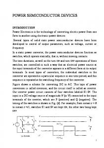
5.2 DVR In this section, a DVR's performance in a sample distribution network is investigated. Fig.10 ,and Fig.11 shows the voltage of one of the phases' load with and without DVR. It is illustrated that a DVR is successful in compensation leading to power quality improvement in the distribution network.
Fig. 13 Compensation of voltage sag resulted from occurrence of threephase short circuit to the ground
The ability of these devices in power quality improvement against various disturbances has been compared and it is available in Table 1 in the appendix.
6 CONCLUSTION In this study, some quantities in power quality have been pointed out according to the IEEE and IEC standards. Moreover, application of custom power devices for improving these quantities are also mentioned. According to this study, DSTATCOM is used in distribution networks to compensate for power quality problems such as unbalanced load, voltage drop, voltage fluctuation, unbalanced voltage and harmonic distortions. A DVR is responsible for voltage sag and swell protection , voltage balancing and compensating for voltage harmonic distortions while UPQC is responsible for compensating for load current harmonic, reactive power compensation, power factor correction, correcting non-load current and regulating DC circuit voltage.
IJSER
Fig. 10 Voltage of one of the phases' load (A) with and without DVR
REFERENCES
Fig. 11 Voltage (Pu) of one of the phases' load (A) with and without DVR
5.3 UPQC Fig.12 shows the waveform of PCC bus's three-phase voltages when subjected to a three-phase short circuit to the ground. According to Fig. 12, the occurrence of a short circuit in one of the buses leads to voltage sag. Fig.13 shows the waveform of PCC bus's three-phase voltages after compensation by a UPQC. Fig.13 shows that the UPQC has delivered balanced sinusoidal voltage to the load by the compensation.
Fig. 12 Voltage sag resulted from occurrence of three-phase short circuit to the ground
[1] Arrillaga, J., Y.H. Liu, and N.R. Watson, Semiconductor Power Devices, in Flexible Power Transmission. 2007, John Wiley & Sons, Ltd. p. 21-56 [2] Pal, Y., et al., A Review of Compensating Type Custom Power Devices for Power Quality Improvement. 2008 Joint International Conference on PowerSystemTechnology.2008.1004-1011. [3] Recommended Practice for Monitoring Electric Power Quality, 2009. IEEEStd.1159,IEEE [4] Coteli, R., et al., Phase Angle Control of Three Level Inverter Based DSTATCOM Using Neuro-Fuzzy Controller. Advances in Electrical and (1): p.77-84 Computer Engineering, 2012.12 [5] M .Brent Hughes and John S. Chan, "Canadian National Power Quality Survey", Power tech Labs Inc , Canada and B.C Hydro, Canada, 1992. [6] J . Bumett, "Survey of Power Quality in High-Rise Air Conditioned Buildings", Power Electronics and Variable-Speed Drives Conference, 2628October1994. [7] Bilgin, H.F. and M. Ermis, Design and Implementation of a CurrentSource Converter for Use in Industry Applications of D-STATCOM. Ieee TransactionsonPowerElectronics,2010.25(8):p.1943-1957. [8] Najafi, E., A.H.M. Yatim, and Ieee, A D-STATCOM Based On Goertzel Algorithm for Sag Detection and a Novel Current Mode Controller. Iciea 2010: Proceedings of the 5th Ieee Conference on Industrial Electronics and
IJSER © 2013 http://www.ijser.org
International Journal of Scientific & Engineering Research, Volume 4, Issue 5, May-2013 ISSN 2229-5518
Applications, Vol 2. 2010. 441-446 [9] Xi, Z., et al., Improving Distribution System Performance with Integrated STATCOM and Supercapacitor Energy Storage System, in 2008 Ieee Power Electronics Specialists Conference, Vols 1-10. 2008. p. 13901395 [10] Cetin, A., et al., Reactive power compensation of coal convetor drives by using D-STATCOMs, in Conference Record of the 2007 Ieee Industry Applications Conference Forty-Second Ias Annual Meeting, Vols. 1-5. 2007 p.1731-1740. [11] Xu, S., et al., Development of a D-STATCOM prototype based on cascade inverter with isolation transformer for unbalanced load compensation.2005 [12] J. A. Oliver, R. Lawrence, B. B. Banerjee, .How to Specify PowerQuality-Tolerant Process Equipment. IEEE Industry Applications Magazine, Sept/Oct 2002. [13] E. Acha , V.G. Agelidis , O. Anaya-Lara, T.J.E. Miller, .Power Electronic Control in Electrical Systems. MPG Books Ltd., BODMIN, Cornwall,FirstPublished2002. [14] Shiva Swaminatham , Rajat K. Sen, .Review of Power Quality Application of Energy Storage Systems .Contractor Report, SAND98-1513 [15] CUSTOMPOWER - State of the art., Report by CIGRE WG14.31,2000. [16] T.Devaraju and V.C. Veera Reddy, Role of custom power devices in Power Quality Enhancement: A Review .International Journal of EngineeringScienceandTechnologyVol.2(8),2010,3628-3634 [17] Cetin, A. and M. Ermis, VSC-Based D-STATCOM With Selective Harmonic Elimination. Ieee Transactions on Industry Applications, 2009. 45(3): p. 1000-1015.
49
[29] Vinod K hadkikar," Enhancing Electric Power Quality Using UPQC: A Comprehensive Overview ," IEEE TRANSACTIONS ON POWER ELECTRONICS, VOL. 27, NO. 5, MAY 2012. [30] Olimpo Anaya-Lara and E. Acha," Modeling and Analysis of Custom Power Systems by PSCAD/EMTDC" IEEE TRANSACTIONS ON POWER DELIVERY, VOL. 17, NO. 1, JANUARY 2002. [31] Yash Pal, A. Swarup, and Bhim Singh," A Review of Compensating Type Custom Power Devices for Power Quality Improvement," Power System Technology and IEEE Power India Conference, 2008. [32] Nikita HariK ,Vijayakumar, Subhranshu Sekhar Dash," A Versatile Control Scheme for UPQC for Power Quality Improvement," IEEE InternationalConference(ICETECT),2011. [33] Jovica V. Milanovic´, and Yan Zhang," Modeling of FACTS Devices for Voltage Sag Mitigation Studies in Large Power Systems ," IEEE TRANSACTIONS ON POWER DELIVERY, VOL. 25, NO. 4, OCTOBER 2010. [34] R.J. Nelson et al., “Requirements for Dynamic Voltage Restoration to Relieve Distribution System Voltage Sags”, American Power Conference, April 1995. [35] Stewal1 M. Ramsay Patrick E. Cronin, “Using Distribution Static Compensator (D-STATCOMs) To Extend The Capability Of VoltageLimited Distribution Feeders”UMSGroup,2001.
APPENDIX
IJSER
[18] Yao, X.-l., et al., LCL output filter design and the influence to the D-STATCOM compensation characteristic. 2011 International Conference on Electronics, Communications and Control. 2011. [19] Noroozian, R., A Performance Comparison of D-STATCOM and DC Distribution System for Unbalanced Load Compensation. International Review of Electrical Engineering-Iree, 2012. 7(2): p. 4194-4207 [20] Meng, X.-p., et al., Controlling Study of D-STATCOM Based on Reinforcement Learning Adaptive PID. 2009 Ieee International Conference on Automation and Logistics. 2009. 1208-1211 [21] Masdi, H., et al., Design of a prototype D-statcom for voltage sag mitigation. National Power & Energy Conference: PECon 2004, Proceedings. 2004. 61-66. [22] Antonio Moreno-Munoz, Daniel Oterino , Miguel," Study of sag compensation with DVR," IEEE MELECON 2006, May 16-19, Benalmadena (Malaga), Spain [23] M.Osbome , R.H. Kitchin And H .M. Ryan," Custom Power Technology In Distribution System An Overview, " lEE Symposium, Reliability And Security Of Distribution Systems1995. [24]: P. Daehler ,R . Affolter ," Requirements And Solutions For Dynamic Voltage Restorer ,A Case Study," ABB Review 1/2001. [25] Ravilla Madhusudanl, Ramamohan Rao," Modeling and Simulation of a Dynamic Voltage Restorer (DVR) for Power Quality Problems Voltage Sags and Swells," IEEE- International Conference On Advances In Engineering, Science And Management (ICAESM -2012) March 30, 31,2012 [26] M. Aredes, “Active Power Line Conditioner” Dr.-Ing. Thesis, Technische University Berlin, Berlin, Germany, March 1996. [27] M. Aredes , J. Hafner , K. Heuman, “A Combined Series and Shunt Active Power Filter”, IEEE/KTH Stockholm Power Tech Conf , Power Electronic, Sweden, June 1995, PP.237-242. [28] D.Graovac, V .Katic And A. Rufer ," Power Quality Compensation Using Universal Power Quality Conditionering Systems (UPQS) ," IEEE Power Engineering Review, December 2000.
TABLE I ABILITIES OF CUSTOM POWER DEVICES ON POWER QUALITY IMPROVEMENT
Type of
Voltage
Voltage
device
Sag
Swell
Transient
D-
-
∗
∗
DVR
∗
∗
UPQC
∗
UPQS
Voltage
Harmonic
Interruption
∗
-
-
∗
∗
∗
-
∗
∗
∗
∗
-
∗
∗
∗
∗
∗
-
-
-
∗
-
-
-
SSTS
∗
∗
-
-
-
∗
SSCB
-
-
-
-
-
∗
APF
-
-
∗
-
∗
-
fluctuations
STATCOM
SA
SA= Surge Arrester, APF= Active power filter
IJSER © 2013 http://www.ijser.org