ogy Converence, Caesars Palace, Las Vegas, Nevada,. May 1995, Components, Hybrids, and Manufacturing. Technology Society, IEEE, pp. 780{785.
Performance Evaluation of Micromechanical Binary Phase-only Holographic Optical Elements David A. Winick Bruce E. Duewer S. Palchaudhury Paul D. Franzon Integrated Electronic Systems Laboratory Department of Electrical and Computer Engineering North Carolina State University Box 7911 Raleigh, NC 27695 http://www.ece.ncsu.edu/erl/ Abstract | This paper presents some results of our development and test e�orts in micromachine design for optical modulation. In this work, we have developed, using a readily available surface micromachine fabrication process (MUMPs), a series of arrayed micromirror elements. These element arrays form phase-mostly spatial light modulators (SLM's), similar to Texas Instruments'
exure beam micromirror device (FBMD) [1]. Characteristics that distinguish our elements from those of TI include: integrated support posts to stabilize the elements at points beyond pull-in potential, non-metallic supporting structures to reduce di�ractive noise, bistable drive capabilities without the need for transistor arrays, and greater mirror surface stability. Sections 1 and 2 describe our elements (EmBMP's). Their arrayed operation is covered in Section 3. Optical evaluations in Section 4 measure the feasibility of these devices in the application of optical interconnect, as well as bracket further discussion concerning the use and technology requirements. Key words: holographic optical interconnect, spatial light modulators, digital micromirror devices.
1 Introduction The use of micro-electro-mechanically actuated elements for micromirror modulation of light has been successfully demonstrated by several parties [1] [2] [3]. However, despite the speed and cost advantages over optoelectronic solutions [4], their use in di�ractive free-space optical beam routing has yet to gain acceptance. This is due to the size di�erential that still exists between MEMS and optical wavelengths. In order to use these devices in di�ractive modulation, micromirrors must be optically stable, and their placement must at least approximate quarterwavelengths. Additionally, space-bandwidth-products demand large arrays of tightly-spaced elements. The element arrays discussed in this paper are operated
in digital mode, to approximate binary holographic elements, with applications in optical interconnect and projection display generation. The actuation characteristic of these elements, under proper biasing, exhibits a bistability that would enable low-power, high-yield elements that can be addressed progressively, in the form of a passive matrix. The ability to address an N � N array using O(2N) lines from the periphery, rather than O(N 2 ) lines or vertically-integrated logic, allows for relatively compact and inexpensive layout. A detailed explanation of this addressability is included in Section 3. The design of these elements attempts to tackle several optical concerns, as well. The rst of which is phase error. As exible beams are actuated toward points of instability, deviations in thin- lm amorphous material size, shape, and density would otherwise lead to deviations in mirror position. Most of the e�ects of these deviations are averted in our devices, which are driven beyond this region of instability. Stable states are kept as far from the pull-in condition as possible, in order to maintain stability.
2 Electro-mechanically Bistable MEMS Pistons In this section, we discuss the design of electromechanically bistable MEMS pistons (herein referred to as EmBMP's) and their use as phase modulation elements. When arrayed, EmBMP's provide a compact, low-cost, low-power, and potentially e�cient means for free-space optical modulation.
2.1 Theory of Operation EmBMP's are micromirrors, fabricated in a micromachining process that provides a at metal surface to re ect a free-space wavefront. The wavefront phase is modulated by mechanically re-positioning these micromirrors in the wavefront. The particular MEMS elements to which we
V refer in this paper are termed `pistons' after their up and down directions of movement. NMh EmBMP's are controlled by mechanical placement of -B set an upper capacitive plate relative to a lower plate, on the substrate. The plates are manufactured in an initial placement which re ects an `up' position (d = d0); as the plates +Vswitch are moved closer together, the capacitance increases, and a `down' position is obtained (d = d0 ? Gapstop ). The el-Bhold NMl ement exhibits a strict two-position (`up/down') behavior due to a bistability in the electrostatic actuation that is -V switch used to move the plate. Flexure beams used to support the upper plate act as -Breset springs. At least two must be used on each EmBMP for dpi drel 0 d symmetrical stability; three can provide better stability in a hexagonal con guration, but keeping the beams long and of minimal count will reduce the necessary driving Figure 1: Electrostatic characteristic, voltage vs. displacevoltage. The electrostatic actuation (displacement) curve ment of the two capacitive plates follows an equation which is the sum of the capacitive actuating force and the returning (spring) force of the supporting exure beams: movement between stable states is drawn over a portion of its characteristic curve below: 3 F cap L Since the mass and mechanical displacement is small, y(F) = 6NEI the switching speed of these devices is dependent on the pull-in voltage and mechanical settling time. An increase where Fcap is the force across two parallel plates of area A, in switching voltage can vary the pull-in speed nearly lingap distance d = d0 ? y(F), and dielectric constant �; and early. The release speed, neglecting damping, is largely limited by the natural frequency, and therefore length, of the the other variables de ne the supportive structure: the mirror-mass-coupled springs. Device speeds are ex2 pected to be in the 10's to 100's of kHz range, depending Fcap = �V2d2A on structure and drive method. This pull-in and release cap speed are damped mainly by the `squeeze- lm' property [5] of air owing between the two plates. In an array of L = beam length such elements this ow is limited by the space between N = number of beams each element, and so is a function of mirror area coverage E = Young's modulus for the elements. I = inertial moment
X
Mechanical operation of the EmBMP occurs across a region of instability known as the \pull-in". It is at this point that one of the two opposing forces overcomes the other. A mechanical stop is included to prevent the capacitive gap from closing completely; and an electrical bias is driven a marginal distance above the minimum-gap release voltage and below the pull-in voltage, to hold the switch in a stable position. From here, a small switching voltage can be used to open and close the switch. Because the elements are capacitive in nature, they can easily store charge, with very little dissipation occurring only through the drive circuitry to maintain their positions. Furthermore, a slight modi cation of the previously explained drive method can take advantage of this (Figure 1 and Table 2.2), allowing large arrays of switches to be controlled via row and column strobe lines, as described in the next section. An advantage of this method is cost: these switches can be fabricated in a process that does not need transistors, and thus does not predicate corresponding dopant levels. A representation of the EmBMP's
2.2 Fabrication
We have been researching these devices since the beginning of MCNC's MUMPs process availability. They provide a mechanical device with the least amount of reliance on material quality or environmental wear-and-tear. The elevation of a very simple piston element design is shown below: MCNC's surface micro-machining is a process by which a structure of thin lm materials layered on a substrate is subjected to a nal fabrication stage that etches away any exposed sacri cial material. This nal etch of chosen material results in movable mechanical structures. Mechanical actuation of these particular structures is then transduced from electrical energy sources (voltage) through the principle of electrostatics. This process by which we created the elements discussed below consists of layers as described in [6]. The polysilicon layers, deposited via LPCVD, are Phosphorus doped and annealed for reduced internal stresses and ne grain
We have tested piston type 12M1D2 devices to reliably operate at pull-in and release voltages of 28.6V and 19.5V , respectively. Although fringing e�ected the actual capacitance of these devices (Figure 4 shows di�erence between Fastcap data and parallel plate model), these drive voltages correspond closely to the design VVrel ratio. Other dePI vice types have o�ered correspondingly similar responses, as well, with error likely due to lm elasticity or thickness deviations. 1.4e-14
Figure 2: Typical piston array layout
Selects
(Xi ; Yj )
+Vswitch +0V
+Breset
+Bhold
+Bset
hold reset
hold hold
set hold
Table 1: EmBMP state control line voltages
2.3 Analysis and Outlook The EmBMP drive capacitance must meet the following equation in order to fall beyond pull-in at minimum height (see characteristic curve): (d0 ? Gapstop) < 32 d0 In simple geometries pull-in typically occurs after the top plate has moved 1/3 of its distance toward the bottom plate; the voltage at this point is VP I . Following pull-in, the voltage across the plated must be reduced in order to return the top plate to an `up' position; this release voltage is termed Vrel . A Gapstop is built into each element to prevent the upper and lower plates from contacting. For maximum stability (resistance to driver noise), a ratio should be chosen, in order to maintain small VVrel PI stability points at a steeper portion of the characteristic. Increasing the number of beams will increase angular stability, and thus maintain operation near this curve. Beam length and capacitive area can then be selected for appropriate drive levels and speed.
Capacitances
1e-14
8e-15
6e-15
4e-15
2e-15
0 2.4e-06
2.2e-06
2e-06
1.8e-06
1.6e-06 Air Gap
1.4e-06
1.2e-06
1e-06
8e-07
Figure 4: 3D data vs. parallel plate model 10 VPI12m1e2(s)-VREL12m1e2(s) VPI12m1e2b(s)-VREL12m1e2b(s)
9 8 Pull-in minus Release Voltage (V)
size. Reactive ion etching (RIE) is used to pattern all of the layers, except the metal and nitride. The metal is patterned by lift-o�. And the nitride layer acts to isolate the structure from the substrate, and is consequently unpatternable. The process also includes the ability to etch dimples, 7500� A deep, into the rst layer of oxide. Use of this etch along with the calculated over-etch of other layer combinations allows us to build EmBMP's with many gap heights. These various gap heights result in the fabricated element designs which have characteristics shown in Figure 3 (`down' position gap heights for each curve are depicted by the horizontals of like line-type).
drive_c(z0) signal_c(z0) fc_drive fc_signal
1.2e-14
7 6 5 4 3 2 1 0 2e-05
3e-05
4e-05 5e-05 6e-05 7e-05 8e-05 Length of Element Side (period ‘s’ in microns)
9e-05
0.0001
Figure 5: EmBMP switching voltage estimation
3 Arrays The EmBMP's are arranged in a 2-dimensional array, where each element micromirror acts to re ect a chosen phase level of an incident beam, approximating a holographic optical element [7]. Both rectangular and hexagonal arrays have been designed, with center-to-center spacing periods no less than 42�m, limited by feature size and design rule constraints. In order to conserve space, one direction of strobe lines connects to the lower electrodes using 0th -layer polysilicon, while the other connects upper
90 pis_1de2m2_54(d) pis_1dm1de2_52(d) pis_1dm2_54(d) pis_1e2m1d_62(d) pis_1m1d_50(d) pis_1m1e2_76(d) pis_12m1e2_52(d) pis_1m1e2_58(d) pis_1dm1de2_42(d)
80
70
Actuation Voltage
60
50
40
30
20
10
0 2.4e-06 2.2e-06 2e-06 1.8e-06 1.6e-06 1.4e-06 1.2e-06 1e-06 8e-07 6e-07 4e-07 2e-07 Gap Height
0
Figure 3: HC4 piston actuation characteristics electrodes through the springs. By alternating element rotations (see Figure 2), it is possible to share anchors and extend springs across opposing sides of each element.
3.1 Programming the Elements Programming of the array element positions is performed based on two sets of voltage levels reaching each element (see Table 2.2). Figure 1 shows how the voltage across each piston can be divided into a switching voltage, Vswitch, and a bias voltage. ?Bhold is chosen just above the release level, ?Bset is chosen just below the pull-in level, and +Vswitch becomes the voltage in between. Thus when switching voltages ( +0, +Vswitch ) are carried on row strobes and bias voltages ( ?Bset , ?Bhold , ?Breset ) are carried on column strobes, the array elements can be programmed row-by-row. In order to hold the programs of all the rows, ?Bhold should be maintained on each. To set (\down") certain elements in a row, the corresponding row strobe should carry ?Bset , and the column strobes for those elements should carry +Vset. Likewise, to reset (\up") certain elements in a row, the corresponding row strobe should carry ?Breset , and the column strobes for those elements should carry +0V .
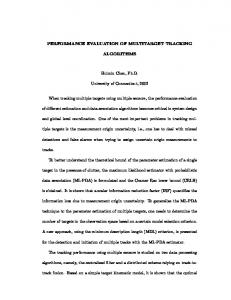
4 System Evaluation Evaluation of EmBMP performance in this section is based upon its ability to modulate and incident optical wavefront as a programmable holographic optical element, for beam steering and focusing. The use of a mosaic structure, such as that found in EmBMP, for display generation exhibit several interesting modulation transfer function properties which are beyond the scope of this paper. The mosaic structure is formed by pixelation in the EmBMP modulator. Each micromirror is spaced from its neighbor in order to provide freedom of movement. Unfortunately, this spacing causes some loss in incident power. Part of that loss is due to light hitting the spaces instead of the micromirrors. And part is due to a di�ractive envelope function that is created by the e�ective aperture of each micromirror in the EmBMP spacing. The micromirror coverage area of each element has drastic e�ects on optical e�ciency. We have found that for an EmBMP array of 64 � 64 elements, a coverage of 88% (equal to that of TI's commercial micromirrors) and size of twice the incident beamwidth is necessary to maintain less than 1dB loss simply due to light not reaching the micromirrors. While this array is possible with current
technology, it does pose some system topography limitations due to its size. One method of compensation, which we are currently investigating, is the use of di�ractive microlenses, to give an e�ective 100% ll-factor to each micromirror.
4.1 Beamsteering An EmBMP array can be modeled as an array of like apertures. Consequently the resulting wavefront is calculated as the convolution of the shape function, de ned by the array program, and the envelope function, de ned by micromirror coverage. This envelope function acts to reduce the e�ciency of the system for larger beamsteering angles. Another source of loss in beamsteering is the spacebandwidth product:
Figure 6: Simulated EmBMP beam steering capability
SBWP = (Bd)2 where B is the highest programmable spatial frequency (and smallest increment, therefore, between each frequency), and d is the size of the array (and thus the number of increments that can be programmed). The SBWP describes the maximumtheoretical number of target directions that can be independently speci ed. Since the size of EmBMP element is still relatively large compared to wavelength, a reduction in the number of programmable grating periods at small di�raction angles is apparent. Furthermore, since the binary nature of the EmBMP only allows Figure 7: EmBMP phase program for F/57 lens two-phase programming, any di�raction will be symmetrical; consequently, the usable output plane must be divided in half, in both dimensions. Simulated output of a onedimensional grating program, at maximum steering angle (Nyquist limit), is shown in Figure 6, for a 32 � 32 ar- 5 Conclusions ray of 10�m elements, and near-infrared wavelength. Loss can be attributed to both the negative order and higher orders. A partial solution to this problem, which we are Flexure-beam actuators have been proven as high yield also currently investigating, is the addition of a constant and high reliability MEMS devices, even in large arrays. (quarter) phase to half of the array elements, in order to Similardevices are already incorporated in commercialdisrecover power from the negative di�raction orders. play products by Texas Instruments and airbag deployment mechanisms by Analog Devices. The compactness and long life of EmBMP devices, due to minimalwear, sup4.2 Focusing plement their applicability as optical modulation mechaEmBMP arrays can also be programmed as a Fresnel nisms. With proper layout techniques and fabrication prolens. Figure 7 shows the phase program of an F/57 lens cess , we feel these modulator arrays can be designed to t in a 32 � 32 array with 30% micromirror coverage, as we betwixt free-space optical beam paths, for beam steering, have fabbed in MUMPs. The resulting intensity pro le, signal routing, and micro-adaptive optics. Electro-mechanically bistable MEMS pistons can be at focal length, is shown in Figure 8. When compared to that of an F/100 program (Figure 9, you can see that, like built with low-cost materials, driven at relatively low opbeamsteering, higher-order noise becomes apparent when erating power, and layed out in a reasonably small footapproaching maximumprogrammable frequencies. Encod- print for optical modulation. We are currently investigating schemes to optimize di�raction e�ciency of the out- ing their continued technology advancement and developput, such as phase rotation, low-resolution encoding, and ment for chip-to-chip optical data lines and airborn laser radar systems. simulated annealing, are being investigated.
[3] Frank Merat and Mehran Mehregany, \Integrated micro-opto-mechanical systems", in MicroOptics/Micromechanics and Laser Scanning and Shaping, M. Edward Motamedi and Leo Beiser, Eds., San
Figure 8: EmBMP output for F/57 program
Jose, CA, Feb. 1995, pp. 88{98. [4] D. C. O'Brien, R. J. Mears, T. D. Wildinson, and W. A. Crossland, \Dynamic holographic interconnects that use ferroelectric liquid-crystal spatial light modulators", Applied Optics, vol. 33, no. 14, pp. 2795{2803, May 1994. [5] Gary Keith Fedder, Simulation of Microelectromechanical Systems, Ph.D. dissertation, University of California at Berkeley, Sept. 1994. [6] Karen W. Markus and David A. Koester, MultiUser MEMS Process (MUMPs) Introduction and Design Rules, MCNC, Electronic Technologies Division,
Mar. 1994. [7] David A. Winick, W. Michael Teague, and Paul D. Franzon, \A micro-machined approach to optical interconnect", in 45th Electronic Components and Technology Converence, Caesars Palace, Las Vegas, Nevada, May 1995, Components, Hybrids, and Manufacturing Technology Society, IEEE, pp. 780{785. Figure 9: EmBMP output for F/100 program
Acknowledgments This work is accomplished with much needed support, and the authors wish to thank the following funding sources: NSF for Dr. Franzon's Young Investigator's Award, Motorola and IEEE/CPMT for laser technologies and Mr. Winick's Fellowship, and DARPA/USAF for related contracts and grants. Also to the software developers for use of their tools: Cadence, Fastcap, and LightPipes.
References [1] Tsen-Hwang Lin, \Integration of micromirror and mixed-signal ics for optical information processing", in Micro-optics/micromechanics and laser scanning and shaping, San Jose, CA, Feb. 1996, SPIE { The Inter-
national Society for Optical Engineering, pp. 78{87.
[2] Gleb Vdovin, Simon Middelhoek, and Lina Sarro, \Spatial light modulator based on the control of the wavefront curvature", Tech. Rep., Laboratory of Electronic Instrumentation and DIMES, Delft University of Technology, The Netherlands, 1995.