IEEE International Conference on Communications 2013: IEEE ICC'13 - Workshop on Radar and Sonar Networks (RSN)
Performance Evaluation of Modified OFDM for Underwater Communications Prashant Kumar
Preetam kumar
Electrical Engineering Department Indian Institute of Technology Patna Patna, India
[email protected]
Electrical Engineering Department Indian Institute of Technology Patna Patna, India
[email protected] OFDM transmits signals over several orthogonal carriers concurrently making its performance robust with rational spectral efficiency and reasonable data transmission rate. The convergence of high-capability, low-power digital signal processors (DSPs) and advances in acoustic channel modeling and communication theory has allowed several commercial and scientific OFDM based underwater applications to emerge.
Abstract—Conventional orthogonal frequency division multiplexing (OFDM) can reduce errors in underwater channels but frequency selective fading can still degrade the data on carriers near deep fade regions. Recently spread-OFDM (SOFDM) which combines the properties of spread spectrum with multicarrier communication has become popular. In this paper spreading by Walsh-Hadamard (WH) codes, discrete Fourier transform (DFT), discrete cosine transform (DCT) and carrier interferometry (CI) codes have been compared for underwater acoustic communication using OFDM. The spreading technique not only helps overcome frequency-selective and multipath fading but also provides reduced peak to average power ratio (PAPR). The performance of this modified OFDM scheme is evaluated in terms of bit error rate (BER) and PAPR. Simulation results show that with CI-SOFDM it is possible to achieve a BER of 1e-4 at 15dB signal to noise ratio. It is also shown that CI-SOFDM offers best PAPR performance. To further improve the BER performance a two level orthogonal spreading by WH followed by CI-SOFDM is also evaluated for underwater communication. The proposed scheme exploits the spreading gain diversity of WH code and phase characteristic property of CI signal to achieve a further gain of 1dB at a BER of 1e-4.
However OFDM has high peak to average power ratio (PAPR) as one of its main shortcomings. Several methods of reducing PAPR have been proposed and a comprehensive comparison between these in terms of power loss, distortion, data rate loss, and extra processing can be found in [2]. In this work the performance of WH-SOFDM, CI-SOFDM, DCTSOFDM, DFT-SOFDM and WH-CI-SOFDM systems in the UWA channel is evaluated using computer simulation. The remaining part of the paper is organized as follows: Section II presents the basics of OFDM system and the concept of spread OFDM as applied to underwater acoustic channel. Section III describes the system model, the underwater acoustic channel and simulation parameters. Section IV concludes the paper with a discussion over the simulation results.
Keywords— Underwater acoustic communication; WalshHadamard code; SOFDM; CI code; DFT; DCT; PAPR; BER
I.
II.
In conventional OFDM the incoming serial data stream is split into N parallel streams, following which an N (N being the total number of subcarriers being used) point IFFT operation is performed resulting in a complex baseband OFDM signal
INTRODUCTION
A reliable, high-speed acoustic link is of great importance for transmission of time-critical sea data from submerged sensors, real-time underwater video transmission for ocean exploration, undersea automated surveillance, communication between manned/unmanned underwater vehicles, etc.
1 x[m] 2N
N 1
s[n]e
j
2n m N
n 0
(1)
th
The Underwater acoustic (UWA) channel suffer from frequency-dependent attenuation and has low propagation speed of sound, around 1500 m/s, making UWA communication a tough job, and compel specific system design. The underwater acoustic communication has a poor data rate of only tens of kilobits per second for low ranges up to 1 km, and it has even poorer data rates at longer ranges [1]. Since underwater acoustic sensor network (UWASN) has nodes having limited power, reducing the transmission power may increase network life span but at the cost of increased bit error rate (BER), as signal to noise ratio (SNR) might not be high enough to ensure satisfactory information transmission.
978-1-4673-5753-1/13/$31.00 ©2013 IEEE
SPREAD OFDM
x[m] is the m time domain sample of the OFDM symbol, 0 ≤ m ≤ N-1 and s[n] is the in-phase and quadrature symbol transmitted on the nth subcarrier, 0 ≤ n ≤ N-1. The OFDM symbol is seen as the inverse fast Fourier Transform (IFFT) of the data symbols s[n]. x[m] can be transmitted using in-phase and quadrature modulators. To recover the symbols at the receiver, FFT operation is performed. Spectral voids are always present in frequency selective multipath channels like the UWA channel and can severely distort or annul out the OFDM carriers that are in their neighborhood, resulting in a loss of the symbols carried by
967
those subcarriers. This ultimately results in a high BER and bandwidth wastage because of the need for retransmission of the lost data. For long propagation delay UWA channel retransmission is not appreciated. Use of forward error correction (FEC) technique is quite feasible. Another approach is to scatter the groups of data symbols over the entire bandwidth. This technique is called code spread (CS) OFDM. CSOFDM or simply SOFDM enjoys the spreading gain of CDMA along with multicarrier transmission [3]. The data symbols are scattered over the complete bandwidth such that every individual subcarrier bears a linear combination of all the data symbols. Even if some subcarriers are faded intensely, then also there is possibility to recover the total transmitted symbols. At the receiver spread symbols are simply separated by the use of linear matrix operation.
Wm Wm
sW s [n]
WN N
(2)
(3)
In case of CI spread OFDM, let the M bit input data be di,{di,0 ≤ i ≤ M-1} and the corresponding symbols after binary phase shift keying mapping be: xl, {xl = 2d i -1,0 ≤ l≤ M-1}. On spreading by CI matrix, the spread symbols can be represented by Sk, {Sk=IFFT(xl)}
(4)
N is used to keep the average normalization constant energy of the vector unchanged. As the coefficients of WHT are always “+1” and “-1” the IFFT of the vector sw[n] has a lower PAPR compared to standard OFDM. The inverse WHT (IWHT) is also obtained by multiplying the transformed vector , sW[n], by the normalized WH matrix WN i.e.,
WN N
M 1
S k xl e j 2lk / M
l 0 (8) These CI spread symbols {Sk, 0 ≤ k ≤ M-1} are mapped onto M subcarriers. Oversampling by a factor Q is used to approximate the true signals. The Q-time oversampled samples can be obtained by performing QM-point IDFT on the data block Sk. The resulting frequency domain symbols Xk are then transformed to the time-domain symbol sequence
(5)
The WH-SOFDM system model is only a slightly modified OFDM model with a spreading block before the IFFT operation and a dispreading block after the FFT operation. In SOFDM, the frequency domain signal is multiplied by a WH spreading matrix before it is fed to the IFFT [4]. The WH matrix can be generated recursively for sizes a power of two. The WH transform is an orthogonal linear transform that can be implemented by a butterfly structure as the IFFT and since the WH and IFFT transforms can be combined and calculated with less complexity than the IFFT alone which means that the system complexity is reduced by applying WH spreading.
^ x n ,0 n N 1 by an IFFT operation.
X n IFFT( X k ) nk
The transmitted OFDM symbol is given by
s WN x IFFT N
is an AWGN vector of
B. CI- spread OFDM A new multi-carrier modulation into the UWA channels which is called Carrier Interferometry OFDM (CI-SOFDM) was introduced in [5]. CI-SOFDM has a low PAPR characteristic and inherent frequency selective combining, which makes it a very attractive signaling scheme in frequency selective fading channels [6]. In CI-SOFDM, each low-rate parallel symbol stream is simultaneously modulated onto all N carriers by the application of a unique orthogonal complex spreading sequence (applied in the frequency domain). This creates frequency diversity benefits for each symbol stream, leading to high performances. Additionally, the use of carefully selected complex spreading sequences eliminates large peaks in power, thereby alleviating PAPR concerns. The CI spreading is implemented using IFFT operation.
where N is the length of the data symbol vector. The
s sW
frequency response estimation and size N.
The WHT of a data symbol vector, s[n] is given by
(7)
^
where W1 = +1. Thus,
W W1 1 1 W2 1 W1 W1 1 1
where h0 is the channel impulse response, H 0 is the channel
A. WH- spread OFDM The Walsh Hadamard Transform (WHT) actually multiplies a 2m-length vector by a 2m X 2m matrix given by
W W2 m m Wm
FFT ( x * h0 w) WN WN s d ^ ^ N H0 N H0
j 2 1 N 1 X ke N N k 0
1 N
1 N
(6)
M 1
Sk e
j 2
nk N
k 0
M 1M 1
x e k 0 l 0
l
j 2
( n Ql ) k N
(9)
As presented to date, the implementation of original CISOFDM is complicated, and it is important to note that the
And the symbol the de-mapper receives is
968
The even symmetric DCT or DCT II is the most popular one. The DCT of x[n] is defined as follows:
receiver is designed for detecting only one information symbol. Although it has been proved that CI-SOFDM improves BER performance by exploiting frequency diversity and depress the PAPR simultaneously, its implementation was complicated and only conceptual transmitter and receiver models have been given in the literature so far.
1 / 2 for k 0 w[k ] 1 for 1 k N
The discrete Fourier transform (DFT) and discrete cosine transform (DCT) are also used in pre-coded (spread) OFDM to reduce PAPR [7], [8].
S k xl e
M 1 M 1
x e k 0 l 0
l
j 2
C e k 0
k
j 2
nk N
(15)
E. WH-spread CI-SOFDM In an attempt to explore the options of two level of orthogonal spreading applied to OFDM for UWA channel, WH-spread CI-SOFDM is simulated. The data symbols are first spread by WH matrix and the obtained output is used to perform CI-SOFDM. Although the complexity of the system will increase and performance will be dependent on frequency and phase synchronization, this new system will combine the spreading gain diversity of WH code and phase characteristic property of CI signal to achieve still lower BER. A similar analysis can be found in [11],[12] for general wireless communication.
nk
1 N
N 1
DCT operation as spreading function is better as it allows for the use of the efficient DCT to scatter and de-spread the data symbols, making the demodulation process simpler. A comparative study between DFT spread OFDM and DCT spread OFDM applied to UWA channel has been done in [10].
nk
j 2 1 M 1 Sk e N N k 0
(14)
1 N
X n IFFT( X k )
1 wk Cx k cos k (2n 1) , 0 n N xn N 2 N k 0 0, otherwise
^ x n ,0 n N 1 by an IFFT operation. X n IFFT(Ck )
l 0 (10) These DFT spread symbols {Sk, 0 ≤ k ≤ M-1} are mapped onto M subcarriers. Oversampling by a factor Q is used to approximate the true signals. The Q-time oversampled samples can be obtained by performing QM-point IDFT on the data block Sk. The resulting frequency domain symbols Xk are then transformed to the time-domain symbol sequence ^ x n ,0 n N 1 by an IFFT operation.
j 2 1 N 1 X ke N N k 0
(13)
The resulting frequency domain symbols Ck are then transformed to the time-domain symbol sequence
j 2lk / M
N 1 2 x[n] cos k (2n 1) , 0 k N C x [k ] 2 N n 0 0, otherwise N 1
C. DFT-spread OFDM In case of DFT spread OFDM, let the M bit input data be di,{di,0 ≤ i ≤ M-1} and the corresponding symbols after mapping be: xl, {xl = 2d i -1,0 ≤ l≤ M-1}. On spreading by FFT operation, the spread symbols can be represented by Sk, {Sk=FFT(xl)} M 1
(12)
( n Ql ) k N
(11)
It is interesting to note that subcarrier mapping becomes very important. At least one half of the subcarriers are cancelled, otherwise the FFT spreading and the IFFT operation of OFDM would nullify each other. However for a spreading by DCT it is not necessary to nullify subcarriers and hence all subcarriers would be useful and carry information.
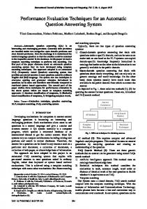
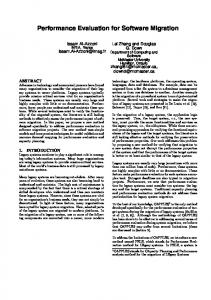
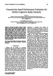
III. SYSTEM MODEL AND SIMULATION PARAMETERS A. System Model The block diagram of a simple OFDM system is shown in figure 1. The system model for spread OFDM is similar to conventional OFDM but slightly modified by including an additional spreading block before the IFFT stage and another de-spreading block after the FFT stage. All the spreading blocks i.e. WH, DFT, DCT and CI blocks in their respective schemes spread information over several subcarriers which results in diversity gain in a frequency selective fading channel. The system model is shown in figure 2. Figure 3 shows the two level spreading scheme WH-CI-SOFDM, where the first level of spreading is done with WH matrix and the second level by CI operation.
D. DCT-spread OFDM Computational efficiency makes DFT very popular, but it has major drawback of being complex and having meager energy concentration. Energy concentration is the property to pack the energy of a sequence into as small number of frequency coefficients as possible. If compaction is high, one only has to transmit a few coefficients. DCT effectively decorrelates the transformed signal and the output has the maximum variance in the least number of transform coefficients. DCT is a better transform, from energy focusing point of view [9].
969
B. Channel Model Channel modeling plays an important role in the effective design of reliable and high data rate system. Shallow acoustic channel has been modeled as a four to five path Rayleigh channel. Time variant fading has been included and additive noise is taken from Rayleigh fading channel model [13],[14]. A time variant and correlated fading factor in the signals amplitude or the power accounts for the multiplicative fluctuation of each individual path. Additive white Gaussian noise (AWGN) for the system is combined at the receiver. After suitable filtering and amplification; and cyclic prefix removal, the received signal is demodulated by FFT algorithm. A serial to parallel conversion of despread signal gives the final data. The channel impulse response can be expressed by
Figure 1. System Model for simple OFDM
M
h(t , ) ai (t ) (t i )
(16)
i 1
where M represents the number of rays used in the multipath channel model. ai(t) and τi(t) are the complex-valued time varying channel magnitudes and the propagation delay of the kth path. A detailed study of parameters used can be found in [14].
Figure 2. System Model for Spread OFDM
C. Simulation Parameters and Assumptions In this paper simple binary phase shift keying modulation has been used and IFFT-FFT based OFDM has been implemented for 64 subcarriers. OFDM, WH-SOFDM, DFTSOFDM, DCT-SOFDM and CI-SOFDM have been simulated for ocean channel. The system specifications are shown in Table I. It is assumed that the receiver has complete channel state information. The receiver is implemented using matched filter. The use of cyclic prefix reduces the effective signaling rate but the benefit gained in terms of simplified equalization is often sufficient justification to accept the reduced data rate. D. PAPR of OFDM System The maximum possible value of the PAPR is N (number of subcarriers), which occurs when all the subcarriers add up constructively at a single point. This value rarely occurs and hence a statistical description is preferred. The complementary cumulative distribution function (CCDF) for a symbol block is used. It is determined by: CCDF = probability (PAPR > PAPR0) IV.
Figure 3. System Model for WH-CI-SOFDM TABLE I.
(17)
SIMULATION PARAMETERS
Parameters No. of transmitted bits
RESULTS AND CONCLUSION
Mapping
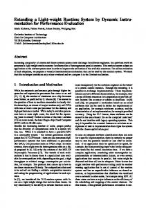
BER and PAPR performances of the different variants of modified OFDM have been evaluated over underwater acoustic channel using Monte Carlo simulation in MATLAB. Figure 4 shows the CCDF of PAPR for OFDM and different modified OFDM schemes. It is observed that CISOFDM offers a PAPR gain of about 1dB at a CCDF of 4e-4 which is marginal compared to WH-SOFDM, DFT-SOFDM and DCT-SOFDM. In conventional OFDM with BPSK modulation the worst case PAPR is N. For CI-SOFDM, the square of maximum amplitude equals the average power in time domain resulting in a PAPR equal to 1, which is much lower than N.
BPSK
Carrier frequency
7 kHz
Signal frequency band: BW
10 kHz
Number of subcarriers: N
64
Coherent time: Tc=1/τmax
210 ms
Maximum Delay Spread: τmax
25 ms
Sub carrier bandwidth: Δf=BW/N
156.25 Hz
Valid symbol duration: TD=1/ Δf
6.4 ms
Cyclic prefix period: TCP≥ τmax
25 ms
Channel
970
DFT-SOFDM 1e6
5-path UWA channel
[11] Mukherjee, M.; Kumar, P.;, “Overloaded WH-Spread CI/MCCDMA with Iterative Interference Cancellation,” Communications Letters, IEEE, vol.15, no.12, pp.1391-1393, December 2011 [12] Xue Li; Chakravarthy, V.D.; Bin Wang; Zhiqiang Wu;, “Spreading Code Design of Adaptive Non-Contiguous SOFDM for Dynamic Spectrum Access,” Selected Topics in Signal Processing, IEEE Journal of , vol.5, no.1, pp.190-196, Feb. 2011 [13] M. C. Domingo, “Overview of channel models for underwater wireless communication networks,” Physical Communication, vol. 1, no. 3, pp. 163–182, 2008 [14] Zielinski, A,; Young Hoon Yoon; Lixue Wu, “Performance analysis of digital acoustic communication in a shallow water channel”, IEEE Journal of Oceanic Engineering, vol. 20, Issue 4 Oct 1995
Figure 5 shows the plot of BER versus SNR for OFDM and different modified OFDM schemes applied to underwater acoustic channel. Simulation results illustrate that for WHSOFDM, the error floor is observed at BER of 4e-4 whereas for both DFT-SOFDM and DCT-SOFDM the error floor is observed at about 8e-5. CI-SOFDM achieves a BER of 2e-6 at 20 dB SNR. Due to the hostile behavior of UW channel it is extremely difficult to achieve a SNR value of even 15 dB at the receiver. Thus it is seen that CI-SOFDM seems to be better solution for UWA communication compared to other variants of spread OFDM. In an attempt to further improve the BER performance, a two level orthogonal spread OFDM (WH-CI-SOFDM) with same specifications is applied to underwater acoustic channel. The BER plot for this scheme is shown in Figure 6. This new proposed system for UWA channel offers an SNR gain of about 1dB at a BER of 1e-5 compared to CI-SOFDM, with small increase in system complexity. This gain is due to the polyphase nature of CI spreading code compared to the binary spreading codes. The simulation results indicate the feasibility of the proposed modified OFDM schemes for UWA communications. REFERENCES [1]
M. Stojanovic and J. Presig, “Underwater acoustic communication channels: Propagation models and statistical characterization,” IEEE Communications Magazine, January 2009, pp.84-89 [2] S. H. Han and J. H. Lee, “An overview of peak-to-average power ratio reduction techniques for multicarrier transmission,” IEEE Wireless Communications, vol. 12, no. 2, pp. 56-65, April 2005 [3] Al-Mahmoud, M.; Zoltowski, M.D.;, “Performance evaluation of Code-Spread OFDM using Vandermonde spreading,” Radio and Wireless Symposium, RWS ’09. IEEE, vol., no., pp.320-323, 1822 Jan. 2009 [4] Dlugaszewski, Z.; Wesolowski, K.;, “WHT/OFDM - an improved OFDM transmission method for selective fading channels,” Communications and Vehicular Technology, 2000. SCVT-200. Symposium on, vol., no., pp.144-149, 2000 [5] Fang Xu; Xiaoyi Hu; Ru Xu;, “A Novel Implementation of Carrier Interferometry OFDM in an Underwater Acoustic Channel,” OCEANS 2007 - Europe , vol., no., pp.1-5, 18-21 June 2007 [6] Wiegandt, D.A.; Nassar, C.R.; Wu, Z.;, “The elimination of peakto average power ratio concerns in OFDM via carrier interferometry spreading codes: a multiple constellation analysis,” System Theory, 2004. Proceedings of the Thirty-Sixth Southeastern Symposium on , vol., no., pp. 323- 327, 2004 [7] Sun Shanlin; Hou Chunping; Yan Lei; Fu Jinlin;, “A Novel Method Based DCT to Reduce PAPR of OFDM Systems,” Wireless Communications, Networking and Mobile Computing, 2008. WiCOM’ 08. 4th International Conference on, vol., no., pp.1-5, 12-14 Oct. 2008 [8] Yonghuai Zhang, Haixin Sun, En Cheng, and Weijie Shen, “An Underwater Acoustic Implementation of DFT-Spread OFDM,” EURASIP Journal on Advances in Signal Processing, vol. 2010, Article ID 572453, 6 pages, 2010 [9] Ahmed, N.; Natarajan, T.; Rao, K.R.;, “Discrete Cosine Transform,” Computers, IEEE Transactions on, vol.C-23, no.1, pp.90-93, Jan. 1974 [10] Kumar, Prashant; Kumar, Preetam;, “Performance Evaluation of DFT-Spread OFDM and DCT-Spread OFDM for Underwater Acoustic Communication,” Vehicular Technology Conference (VTC Fall), 2012 IEEE , vol., no., pp.1-5, 3-6 Sept. 2012
Figure 4. CCDF plot for OFDM and Spread-OFDM
Figure 5. BER plot for OFDM and Spread-OFDM
Figure 6. BER plot for OFDM, CI-SOFDM and WH-CI-SOFDM
971