International Journal of Distributed and Parallel Systems (IJDPS) Vol.1, No.2, November 2010
Performance Evaluation of QoS parameters in UMTS Network Using Qualnet Amandeep Singh Thethi Lecturer, Department of Electronics Engineering Guru Nanak Dev University Amritsar, Punjab, India e-mail:
[email protected]
R.S. Sawhney Sr. Lecturer, Dept. of Electronics Technology Guru Nanak Dev University Amritsar, Punjab, India e-mail:
[email protected]
Abstract— A UMTS network based on the Wide Band-CDMA technology is a 3rd generation telecommunication system which provides various multimedia applications along with the conventional telephony service. These various multimedia applications fall into four different categories, which are differentiated from each other on the basis of required bit rate and delay tolerance etc. parameters. In order to get best Quality of Service (QoS) for a particular application running on the subscriber equipment the parameters of the respective category to which the application belong need to be in a required range. In this work the performance of a UMTS network scenario is evaluated by using various values of the precedence bits of the CBR application. The simulation tool used is QUALNET 5.0. The performance of the scenario according to the respective precedence bits is analyzed by four metrics: average jitter, end to end delay, throughput and UMTS signals received and forwarded to MAC. The comparative analysis of all the four metrics according to the precedence bit values will be carried out and it will be concluded in the last section that which precedence bit gives the best performance for the simulated UMTS network scenario.
Keywords – UMTS, QUALNET, QoS, Precedence.
I. INTRODUCTION Capacity increase was one of the main motivations for introducing 2G systems in the early 1990s. By the late 1990s, the very success of GSM was again raising questions about the future need for yet more spectrum and technology fragmentation was again an issue. The GSM community was initially focused on developing GSM’s circuit and packet switched data services, using HSCSD and GPRS. Both are limited to maximum data rates of less than 50 kbps and neither can support video telephony. Any large scale adoption of such services would also further increase pressures on the available spectrum since the same spectrum is shared between voice and data services. The addition of EDGE technology to GSM can support data rates up to 472 kbps, particularly over the downlink to the mobile terminal, but again only by reducing available voice capacity. So it was clear that more spectrum would have to be made available. DOI : 10.5121/ijdps.2010.1206
57
International Journal of Distributed and Parallel Systems (IJDPS) Vol.1, No.2, November 2010
But this time, the potential seemed to exist for a truly global common solution. The universally accepted result was the WCDMA technology standard. The specifications of WCDMA that have only recently been completed are perhaps ten times longer than GSM, and are almost all entirely different. However, a single global standard still proved to be unachievable. Although Europe and Japan agreed to converge on a common WCDMA standard, the USA both used different frequencies and wanted an evolution path from IS-95. Hence it adopted a variant of WCDMA known as CDMA-2000. So the transition from GSM to WCDMA represents another development challenge that is much more complex even than GSM [1]. The main targets for the 3G are:• Standardize 3G in a manner so that at least part of the 2G network infrastructure can be reused. In the case of GSM and UMTS (Universal Mobile Telephone System), this has materialized to some extent. Certain GSM core network nodes can potentially be reused for UMTS. Also, the UMTS handover requirements state that handover to 2G systems, e.g. GSM, should be possible. Furthermore, it was at least attempted to choose design parameters for UTRA which ease implementation of dual-mode GSM/UMTS handsets; dual-mode operation is expected to be a standard feature of most UMTS handsets. Correspondingly, it is possible to deploy UMTS gradually in a GSM system, where in a first phase only selected sites are equipped with UMTS base stations, while universal coverage is provided by GSM. [2] • Evolve capabilities of 2G systems to meet 3G requirements, for instance through enhancements to the air interface. To give importance of GSM and the large number of advanced features which have been or are still being standardized for this system. • Another challenge for 3G was to bring the best features of mobile communications and the Internet together. Different markets may evolve at different rates, e.g. Europe has medium-level fixed Internet penetration but leads the USA with high mobile communications penetration (based on the one standard — GSM). Conversely, the USA has very high Internet penetration, but an array of different mobile standards and less complete national coverage. 3G networks were designed so as to enable mobile multimedia. The 3rd Generation Partnership Project (3GPP) is a collaboration between groups of telecommunications associations, to make a globally applicable third-generation (3G) mobile phone system specification within the scope of the International Mobile Telecommunications-2000 project of the International Telecommunication Union (ITU).[3]
II.
UNIVERSAL MOBILE TELECOMMUNICATIONS SYSTEM(UMTS)
A main architectural design principle of the universal mobile telecommunications system (UMTS) is the split of the fixed UMTS infrastructure into Core Network (CN) and access network (AN) domains. The technology used in a UMTS network is WCDMA, which provides much higher bandwidth than the conventional CDMA systems. An additional design principle is the logical split of the global architecture into a so-called ‘access stratum’, containing equipment and functionality specific to the access technique (e.g. radio-related functionality), 58
International Journal of Distributed and Parallel Systems (IJDPS) Vol.1, No.2, November 2010
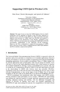
and ‘non-access strata’, as shown in Figure 1.3. The access stratum includes protocols between the mobile terminal and the access network, and between the access network and the serving core network. While the former support the transfer of detailed radio-related information, the latter are independent of the specific radio structure of the access network. This is important, it means that the CN should not be affected by the choice of radio transmission technologies in the access network, such that new types of access networks can be defined as and when required and attached to the existing core network. [2]
Figure 1 Basic logical UMTS architecture The only suitable access network type defined in release 1999 specifications is the UMTS or Universal Terrestrial Radio Access Network (UTRAN), consisting of a set of radio network subsystems. UTRAN is composed of a Radio Network Controller (RNC) and a number of base stations, a base station is termed as Node B in UMTS. The radio technologies featured by UTRAN release 1999 are the UTRA TDD and the UTRA FDD mode. The CN consists of a ‘circuit-switched domain’ or CS-domain, which is composed of Mobile services Switching Centres (MSC) very similar to those already used in GSM, and a ‘packet-switched’ or PSdomain, which is an evolution of the GPRS core network . Accordingly, there are two variants of the Iu interface between AN and CN shown in Figure 1.3, namely Iu-CS and Iu-PS. The fundamental UMTS service principle is to standardize service capabilities rather than the services themselves, which helps achieving flexibility in service provision. With an appropriate set of service capabilities, users, service providers, and network operators should be in a position to define services themselves according to their specific needs. The packet switched core network of UMTS consists of a Gateway GPRS Support Node (GGSN) and a Serving GPRS Support Node (SGSN). The GGSN uses source and destination port numbers from packet header to deduce application type; thus incoming IP traffic is mapped to corresponding UMTS QoS classes. UMTS (Universal Mobile Telecommunications System) is one of the most commonly used standards for third generation 3G) of mobile networks. One of the main UMTS advantages is that UMTS supports IP services with end-to-end QoS (Quality of Service) guarantees.[4][5]
59
International Journal of Distributed and Parallel Systems (IJDPS) Vol.1, No.2, November 2010
Figure 2 UMTS network architecture and interfaces.
III.
THE CONCEPT
The WCDMA is the main radio technology employed in UMTS. In Wide-band Code Division Multiple Access (WCDMA) systems all users share the same time and frequency resources. The variants Frequency Division Duplexing (FDD) and Time Division Duplexing (TDD) were selected by the European Telecommunications Standards Institute (ETSI) in 1998. Although, just like traditional CDMA, the spread spectrum forms the underlying technique for WCDMA but employing a different control channel and signaling, wider bandwidth, and a set of enhanced futures for fulfilling the requirements of 3G systems, it is significantly different from its counterpart. The WCDMA system is compatible with both the 5 MHz wide WCDMA radio channel and the narrow 200 kHz GSM channels. In the following sections an overview of the WCDMA radio technology is represented by the help of its architecture and air interface specifications. The basic features (processes) of WCDMA, spreading and despreading suitable for the air interface are also explained with the related diagrams. W-CDMA (Wideband Code Division Multiple Access) defines the air interface access of the UMTS network. Unlike GSM which uses time division multiple access sceme, W-CDMA allows all users to transmit at the same time and to share the same RF carrier. Further, W-CDMA uses a wider bandwidth (5 MHz) as compared to CDMA IS-95 systems (1.25 MHz). As well, W-CDMA base stations do not require being in system-wide time synchronization. W-CDMA has two modes; FDD (Frequency Division Duplex) mode using separate frequencies for uplink and downlink, and TDD (Time Division Duplex) with uplink and downlink carried in alternating bursts on a single frequency. [6][7][8] WCDMA is based on a hierarchical architecture with the different nodes and interfaces. A terminal, also referred to as User Equipment (UE) in 3GPP terminology, communicates with one (or several) NodeBs. In the WCDMA architecture, the term NodeB refers to a logical node, responsible for physical-layer processing such as error-correcting coding, modulation and spreading, as well as conversion from baseband to the radio-frequency signal transmitted from the antenna. A NodeB is handling transmission and reception in one or several cells. Thus a NodeB is a possible implementation a base station. The Radio Network Controller (RNC) controls multiple NodeBs. The number of NodeBs connected to one RNC varies depending on the implementation and deployment, but up to a few hundred NodeBs per RNC is not 60
International Journal of Distributed and Parallel Systems (IJDPS) Vol.1, No.2, November 2010
uncommon. The RNC is in charge of call setup, quality-of- service handling and management of the radio resources in the cells for which it is responsible. The ARQ protocol, handling retransmissions of erroneous data, is also located in the RNC. Thus, in Release 99, most of the ‘intelligence’ in the radio-access network resides in the RNC, while the NodeBs mainly acts as modems. Finally, the RNCs are connected to the Internet and the traditional wired telephony network through the core network. Most modern communication systems structure the processing into different layers and WCDMA is no exception. The layered approach is beneficial as it provides a certain structure to the overall processing where each layer is responsible for a specific part of the radio-access functionality. [9]
Figure 3 WCDMA radio-access network architecture [9]
IV.
PROPOSED MODEL
Network simulation is a very efficient and cost-effective way to develop new network technologies. By building virtual networks in a lab environment, researchers can test, optimize, and integrate next generation network technologies at a fraction of the cost of deploying physical test beds. QualNet is network modeling software that predicts performance of networks through simulation and emulation. QualNet is the cornerstone for virtual networking labs that enable the deployment of a mind-boggling plethora of applications in wireless, wired and mixed network platforms. The objective of the paper is to evaluate the Quality of Service (QoS) of a Universal Mobile Telecommunication System (UMTS) network with different precedence bits and then to compare them. The QOS is determined by changing the precedence bit of the CBR application. PRECEDENCE BIT - It tells us about the type of QOS being used. Precedence bit can be from value ranging from 0 to 7. The IP Precedence bits allow us to specify what traffic gets what Class of Service. IP precedence is a value that can allow certain traffic to gain priority over other types of traffic. The details of each precedence bit are as follows: 0: Routine (for transmitting routine application data such as e-mail etc) 61
International Journal of Distributed and Parallel Systems (IJDPS) Vol.1, No.2, November 2010
1: Priority (Packets with higher priority will get forwarded first) 2: Network (tells us about the critical path is which path to follow first; intended to be used within the network only) 3: Internet (This bit is intended for use by gateway control originators only) 4: Immediate (This is for the sensitive data which needs to be attended first i.e. delayed data) 5: Flash-override (This is for video-traffic) 6: Flash (This is for higher class data traffic) 7: Critical (This is for VoIP traffic or real time traffic) QUALITY OF SERVICE (QoS) IN UMTS – QoS is defined as the ability of the network to provide a service at an assured service level. QoS in UMTS means the required throughput and delay in a particular service. For UMTS, four different QoS traffic classes are defined, the four QoS classes are:1.
2.
3.
4.
Conversational class: represents highly delay sensitive conversational streaming applications. Examples include telephony speech, voice over IP, and videoconferencing. Limits for acceptable transfer delay are very strict, along with requirements on preserving the time relation between different stream entities. Streaming class: represents real-time streaming applications that are primarily unidirectional. This scheme applies when the user is looking at (listening to) real-time video (audio). The class is characterized by limited delay variations, with no requirements on low transfer delay. Interactive class: and represents the classical data communication scheme characterized by the request-response pattern of the end user. Example applications include Web browsing and database retrieval. A key characteristic for QoS is low bit error rate for transferred packets. Background classes: The fundamental characteristic of this class is that the destination is not expecting the data within a certain time. Data can be sent and received in the background, with low bit error rate and no specific requirements on delay.[10] Table 1 UMTS QoS classes
The first two classes support real time (RT) applications and the last two non real time (NRT) applications. Both the Conversational Class and Streaming Class are distinguished from the Interactive Class by offering a guaranteed bandwidth. 62
International Journal of Distributed and Parallel Systems (IJDPS) Vol.1, No.2, November 2010
The performance and behavior of each of the class is defined by the QOS attributes. The attributes are some adjustable parameters and are applied in both of the circuit switched and packet switched domains. The QoS parameters upon which we guarantee the best service and which are used in the simulation are (1) Average Jitter –As the packets from source to destination will reach the destination with different delays. A packet's delay varies with its position in the queues of the routers along the path between source and destination and this position can vary unpredictably. This variation in delay is known as Jitter. Jitter can seriously affect the quality of streaming audio and/or video. A network could possibly have zero Jitter. Jitter for all the precedence bits are calculated and compared. (2) Average end-to-end delay- Due to queuing and different routing paths, a data packet may take a longer time to reach its destination .The end-to-end delay experienced by the packets for each flow the individual packet delay are summed and the average is computed. (3) Throughput – Throughput is the average rate of successful message delivery over communication channel. It is measured in bits per second (bit/s or bps) and sometimes in data packets per second or data packets per time slot. Due to varying load from other users sharing the same network resources, the bit-rate (the maximum throughput) that can be provided to a certain data stream may be too low for real time multimedia services if all data streams get the same scheduling priority. (4) UMTS signals received and forwarded to MAC: The number of signals received and forwarded to the MAC layer.[4][11]
Figure 4: UMTS Network Simulation
V.
SIMULATION RESULTS A. Average jitter
As we know jitter is the variation in delay suffered by different data packets reaching a destination,thus it is an unwanted parameter. But its also unaviodable in IP based communication systems as we use routers for the data packets and different data packets choose different routes for attaining bandwidth utilization.Thus there is always a little amount of jitter 63
International Journal of Distributed and Parallel Systems (IJDPS) Vol.1, No.2, November 2010
present in the system. The average jitter for the different precedences was compared and it came minimum for precedence “0”.Thus we get best performance at the precedence “0”.
Figure 5: Average Jitter B. Average end-to-end delay Due to queuing and different routing paths, a data packet may suffer with time delay before reception at the destination.The Average end to end delay for the simulated scenario was minimum for precedence “0”.This means system introduces minimum delay for the data packets when we use the precedence “0”, so the performance of the system is best at precedence “0” as compared to the other precedences.
Figure 6: Average end-to-end delay C. Throughput As the throughput is the ratio of the total amount of data that reaches the receiver to the time it takes. So a high throughput is always desirable in a communication system. The simulation results give best result for the precedence “0”. Thus we get best performance at the “0” precedence.
64
International Journal of Distributed and Parallel Systems (IJDPS) Vol.1, No.2, November 2010
Figure 7: Throughput D. UMTS Signals Received and forwarded to MAC The number of the UMTS signals received and forwarded to MAC according to the precedence “0” are shown in the graph. It is shown that at precedence “0” UMTS signals received and forwarded to MAC were maximum as compared to other precedence bits.
Figure 8: UMTS signals received and forwarded
VI.
CONCLUSION
This paper gives overview out of the UMTS system with its architecture and emphasizing to the Quality of Service in the UMTS network. UMTS is considered as evolution step from 2G to advance. The introduction of new WCDMA based air interface imposed new requirements for UMTS Radio Access Network. In this paper, the Quality of Service is analyzed by changing the value of the precedence bit of the CBR application. The values of the precedence bits that have been taken are 0, 1, 4 and 6. It was found that :65
International Journal of Distributed and Parallel Systems (IJDPS) Vol.1, No.2, November 2010
1. Average Jitter was minimum at precedence 0. 2. The minimum average end-to-end delay was also achieved with precedence bit 0. 3. Maximum throughput was achieved with precedence bit 0. 4. UTMS signals received and forwarded to MAC were maximum at precedence 0. Therefore the performance of the UMTS network scenario reached maximum by using the “0” value of the precedence bit. For future work the performance of different UMTS network scenarios can be analyzed under different parametric conditions. The number of nodes can be varied with their respective distances from the server. It would also be interesting to study how the performance of the network can be maximized by simulating the network using different precedence bits.
VII. References [1] C Smith,C Gervelis, “Wireless network performance Handbook”, Chapter 3, Mc Graw-Hill Networks, 2003. [2] “Internet Mobility the CDPD Approach”, http://www.leapforum.org/published/internetworkMobility/one/main.html- visited on February 2010 [3] Alan Clapton,” Future Mobile Networks,3G and beyond, The Institution of Engineering and Techonology”, London, England, 2001. [4] Ritesh Shreevastav, Ciaran McGoldrick, Meriel Huggard “DeliveringImproved QoS and Cell Throughput in UMTS Based HSDPA Networks”, IEEE transaction 2010. [5] Sladana Zoric, Melika Bolic, “QoS signalling in IP multimedia Symposium ELMAR-2009, 28-30 September 2009, Zadar, Croatia
subsystem of UMTS” 51st International
[6] Heikki Kaaranen, Ari Ahtiainen, Lauri Laitinen, Siamak Naghian,Valtteri Niemi, “UMTS Networks Architecture, Mobility and Services” Second Edition, John Wiley & Sons Ltd, 2005. [7] “WCDMA/UMTS wireless networks” www.tek.com/Measurement/App_Notes/2EW.../2EW_17289_0.pdf visited on may 2010 [8] Markus Laner, Philipp Svoboda, Markus Rupp “Outer-Loop Power Control in a Live UMTS Network: Measurement, Analysis and Improvements” Proceedings of the 4th International Symposium on Communications Control and Signal Processing, ISCCSP 2010, Limassol, Cyprus, 3-5 March 2010 [9] Erik Dahlman, Stefan Parkvall, Johan Sköld and Per Beming, 3G Evolution HSPA and LTE for Mobile Broadband,Second edition, Elsevier Ltd.,2008 [10] Lea Skorin-Kapov, Darko Huljenic, Dario Mikic, Danko Vilendecic, “Analysis of End-to-End QoS for Networked Virtual Reality Services in UMTS” IEEE Communications Magazine, April 2004 [11] Ira Weissberger, Ivica Kostanic, Carlos E. Otero “Evaluation of HTTP QoS in a UMTS Network”, IEEE transaction 2010
66