Performance Evaluation of Spatial Domain Error Concealment for Image Recovery. Yefeng Zheng. Electrical and Computer Engineering Department. University ...
Project Report of ENEE739M, spring 2002:
Performance Evaluation of Spatial Domain Error Concealment for Image Recovery Yefeng Zheng Electrical and Computer Engineering Department University of Maryland College Park, MD 20742
Abstract: Many spatial domain error concealment techniques, which are used in decoder to improve visual quality of damaged images, have been proposed in the past years. Each algorithm is based on different assumptions and has different performance under different conditions. However, there is no extensive comparative evaluation available in literature. Performance evaluation helps us to understand the state-of-art of techniques and indicates further research directions. In this paper, evaluation results of spatial domain error concealment for image recovery are presented. Many algorithms are realized and evaluated, such as pixel domain interpolation (PDI), multi-directional interpolation (MDI), projection onto convex sets (POCS) and maximally smooth recovery (MSR), etc. Different algorithms have different performances on different type of regions, e.g. smooth region, region with edge or texture region, etc. In addition to natural images, several artificial images, in which we can control the size, location and relative ratio of different types of regions, are used to test some specified aspects of each algorithm. Our experiments show all algorithms perform well on smooth regions. However, fine texture image is still a challenge. MDI performs well on regions with edges. Maximally smoothness recovery approach has relatively good performance, and low computation complexity. Based on the above observation, we proposed an adaptive version of MSR, using different smoothness measures for different regions. Experiments show, our improvement can get better results than MSR. Keywords : Error Concealment, Performance Evaluation, Pixel Domain Interpolation, Multi-Directional Interpolation, Maximally Smooth Recovery, Projection onto Convex Sets
1. Introduction Various channel/network errors will result in damage or loss of compressed video packages. Usually, video stream is highly compressed by removing spatial and temporal redundancy as much as possible. Two compression techniques make compressed video stream extremely sensitive to transmission errors : motion compensation and variable length coding (VLC). Using motion compensation, damaged blocks in a previous frame will affect the following frames until an I-frame is decoded. With VLC, one bit error in bit stream will cause decoder loss of synchronization and the following bits are un-decodable. One of the most important difference between data stream and video stream is that video stream is robust to high bit error rate. Instead of discarding the whole package and requiring re-transmission, decoder can try to recover lost information from correctly received bits, which is error concealment. Error concealment increases visual quality greatly. For video sequences the spatial and temporal redundancy are helpful for us to recover the lost information. Techniques using these two kinds of redundancy are categorized as spatial domain error concealment and temporal domain error concealment1. This paper will focus on spatial domain error concealment. Several techniques have be en proposed in the past ten years. Some techniques are rather intuitive, such as Pixel Domain Interpolation 2, Multi-Directional Interpolation 3, etc. Error concealment is an ill-posed problem ,
which has no unique recovery of the lost information. Generally, some constraints using a priori information are exploited to confine the feasible solutions. Different techniques try to get “optimal” solutions based on different assumptions4,5. Performance evaluation is very important for researches, which provides better understanding of the state-ofart techniques and indicates future research directions. Different techniques are based on different assumptions, and claim to get better result under certain conditions. However, no extensive comparative evaluations are available in literature. In this paper, we compare different algorithms on different image region types and different transmission errors. Our experiments show all techniques perform well on smooth region because of large dependency among neighboring pixels in smooth region. The reconstruction PSNR is more than 20dB higher than other types of image regions. Fine texture presents great challenge for error concealment. Region with edge lies between these two extremes. Along edge direction, the difference between pixel values is very small. However, cross edge direction, the difference is much larger. Most natural images may not have all these types of regions. Furthermore, the size, location and relative ratio of these region types are uncontrollable in natural images. Hence, artificial images with purely smooth areas or purely lines with different wid th and orientations are much more desirable for performance evaluation. Our comparisons are performed on both artificial images and natural images. For different networks and different compression techniques, three kinds of transmission errors are simulated: block-based random damage, slice-based random damage and block damage with data partition. Our performance criteria include reconstructed image quality, computation complexity, etc. Objective image quality criteria, such as SNR and PSNR, are widely used because they are easy to calculate. Subjective criteria is much more applicable, since most images will be judged by human vision system at last. However, it is very difficult to do large-scale subjective image quality evaluation, we will use objective criteria primarily. This paper is organized as following: brief descriptions of evaluated algorithms are presented in the next section. In section 3, we will discuss our evaluation methods in details. And at last, some conclusions are given, together with several suggestions for future researches.
2. Literature Survey and Proposed Improvement 2.1.
Pixel Domain Interpolation (PDI)
Pixel domain interpolation is a rather intuitive approach2. It assumes the surrounding blocks of the damaged one are correctly decoded, and try to interpolate the lost block using border pixels of surrounding blocks . Two interpolation schemes are proposed : macro-block-based and block-based. For the macro-block-based interpolation, each pixel will be interpolated using four nearest border pixels in four directions. For block-based interpolation scheme, only two nearest border pixels are used for interpolation. If surrounding blocks are damage too, recovered surrounding blocks are used and we do iterative recovery until no further changes to any damaged blocks. This iterative approach is used for all other algorithms in our experiments, if the surrounding blocks are damaged.
2.2.
Multi-Directional Interpolation (MDI)
Interpolation using four surrounding border pixels will blur edges running through the damaged blocks. An improvement of pixel domain interpolation is interpolation along the edge direction3. To do so, we need to estimate edge direction. Edge detection is a difficult problem in computer vision. Instead of extracting edge explicitly, this approach estimate edge direction based on gradient, and quantizes it to eight directions. Then along the edge direction do interpolation. Several edges may run through the damaged block. Hence, several (at most three) interpolation blocks are reconstructed, using different edge directions. At last, multiple interpolations are combined together to get the final concealed block.
2.3.
Projection onto Convex Sets (POCS)
POCS approac h uses a priori information to constrain the size of the feasible solution set. Several a priori properties about typical images are used 4: 1) Smoothness – requires reconstructed samples to be smoothly connected with adjacent image blocks. 2) Edge continuity – requires that edges be continuous. 3) Consistency with known values – requires that correctly received pixel values not be altered by restoration process, and that restored values lie in a known range (e.g. 0-255). POCS is realized as following. Missing block, together with 8 surrounding blocks are transferred to frequency domain using FFT. And the enlarged block is classified to smooth region, or region with edges with different directions. Block classification procedure is similar to multi-directional interpolation approach. Based on the block classification results, adaptive filtering is applied: low-pass filter for smooth regions and edge filter for regions with edge. Adaptive filter realizes smoothness and edge continuity constrains. After that, do inverse FFT. Pixels in the reconstructed missing block are truncated to range 0-255 integers and put back for the next iteration. While, the surrounding blocks are unaltered. This procedure realizes constraints of consistency with known values. Many common constraints such as space-limiting, band-limiting, non-negativity, and bounded energy are known to be convex sets. It has been shown that if the two convex sets intersect one another, then convergence of the solution to a point of intersection is guaranteed. As an iterative approach in nature, POCS is very time consuming.
2.4.
Maximally Smooth Recovery (MSR)
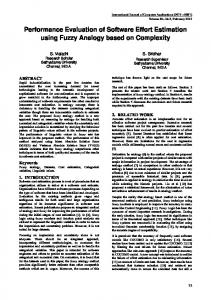
All of the above approaches assume all data of the damaged blocks are lost. However, if using data partition, or RVLC, several DCT coefficients of the damaged blocks will be correctly decoded. Instead of discarding all data, MSR uses the correctly received DCT coefficients and surrounding blocks to reconstruct the damaged block. Since it is an ill-posed problem, constraints ar e needed to confine the feasible solution set. In general, image blocks are smoothly connected with the surrounding blocks. MSR selects such solution that maximizes the smoothness criteria. Two kinds of smoothness measure are proposed in Ref. [5] as shown in Figure 1. Type 1 smoothing constraint is imposed only on the boundary, as shown in Figure 1-(a). Type 2 smoothing constraint is imposed on each pixel in the direction towards its nearest boundary, as shown in Figure 1-(b). In our experiments, only type 1 smoothing constraint is realized and compared with other algorithms.
Figure 1. Illustration of smoothing constraints: an arrow between two samples means that the difference between these samples occurs in the smoothness measure. (a) Smoothing constraint imposed only on the boundary. (b) Smoothing constraint imposed on each sample in the direction towards its nearest boundary. (Figure 1 in Ref. [5] @1993 IEEE) It has been shown5 that the optimal solution aˆo p t (recovered DCT coefficients) can be obtained by linear combination of two parts: correctly received DCT coefficients ~ar , and border pixels of surrounding blocks, b (as shown as the black stripes in Figure 1). aˆ opt = Ab + Ba~r (1) where A and B are two weight matrices. If all DCT coefficients are lost, the second term vanishes, and the optimal solution is just linear interpolation of border pixels.
2.5.
Proposed Adaptive Maximally Smooth Recovery (AMSR)
From following evaluation experiments, we find MSR performs well on smooth region and regions with relatively smooth horizontal or vertical edges. However, it will blur diagonal edges. One possible solution is using second-order der ivative-based smoothness measure 6, which will get better results for step edges. However, it will still blur thin edges. Our improvement is to adaptively use different smoothness measure for different regions. We found that MDI achieves better results on diagonal edges and sharp edges. However, it is much time consuming than MSR. In the proposed approach, we try to combine the merits of these two techniques together. Edge direction classification module of MDI is used to classify the damage block. Instead of classifying the edge into 8 directions, in our preliminary experiments, only 4 directions are used: horizontal, vertical, primary diagonal and minor diagonal. Then for smooth region, type 1 smoothness measure is used, as shown in Figure 1-(a). And for region with different edge directions, different smoothness measures are used adaptively, as shown in Figure 2.
(a)
(b)
(c)
(d)
Figure 2. Smoothness measure for (a) horizontal edge, (b) vertical edge, (c) primary diagonal edge and (d) minor diagonal edge Our approach is similar to Ref. [9], in which the second-order smoothness measure is extended to consider different edge directions.
2.6.
Other Approaches
Several other approaches are not evaluated. Lee etc. used a fuzzy logic -based approach11. Park’s approach is similar to MSR, but with less computation demanding 12. Zeng’s approach is an extension of MDI. Instead of interpolation along 8 directions, his approach allows multiple interpolations along any directions and any number of edges, based on detailed image analysis 10. However, the image analysis is rather tedious and not as elegant as MDI. The DCT domain approach proposed by Ancis etc., can be taken as an interpolation in frequency domain rather than in pixel domain 8. However, in DCT domain, the correlation between neighboring coefficients is much smaller than pixels domain. Several intuitive interpolation approaches are proposed and failed to get good reconstruction result. Neural network-based estimation is exploited and claimed to get better results than MSR.
3. Evaluation Methods 3.1.
Artificial Images
Different algorithms have different performance on different types of regions, e.g., smooth region, region with edge, or texture region, etc. Natural images may not have all these types of regions. Furthermore, the size, location and relative ratio of these region types are uncontrollable in natural images. So, artificial images with purely smooth areas or purely edges with different width and orientations are much more desirable to test some specified aspects of algorithms. Three types of artificial images are created: smooth images, line images and circle images, as shown in Figure 3. Figure 3-(a) shows a smooth image, which is used to evaluate the performance of each algorithm on smooth region. The gray value of each pixel p ( x , y ) takes the form of:
1 p ( x, y) = 255 × exp − ( x − w / 2) 2 + ( y − h / 2) 2 2 2 σ
[
]
(2)
Where σ is an adjustable parameter to control the smoothness of the image. Figure 3-(b) is an image with lines of different directions. The number of lines, line width and line smoothness are adjustable. Line smoothness parameter controls how smoothly the borders of a line are merged into background. The gray values of pixels on line borders are similar to Equation (2). A circle can be taken as a line with different directions along the line, as shown in Figure 3-(c). Since, multi-directional interpolation quantizes the edge direction into 8 angles. We can use circle images to test the effect of such quantization.
(a)
(b)
(c)
Figure 3. Artificial images for evaluation, (a) Smooth image with σ = 100 , (b) Line image with line width of 3 pixels and σ = 5 , (c) Circle image with line width of 3 pixels and σ = 5 Natural images are the real images likely to deal with in real application scenarios. Several standard test images are included in the evaluation too.
3.2.
Evaluation Criteria
Performance criteria include reconstructed image quality, computation comple xity, etc. Objective image quality criteria, such as SNR and PSNR, are widely used because they are easy to calculate. Subjective criteria is much more applicable, since most images will be judged by human vision system at last. However, since it is very difficult to do large-scale subjective image quality evaluation, we will use objective evaluation primarily. PSNR is widely accepted objective criteria of image quality:
255 × 255 PSNR = 10 × log 10 W H 2 ' p ( x, y) − p ( x, y) ∑∑ x=1 y =1
[
]
(3)
where p ( x, y) is the original gray value of pixel ( x, y ) and p ' ( x , y ) is the gray value of the reconstructed pixel. Computation complexity is an important criterion for some applications. For example, the computation power of a desktop computer is much higher than a cell phone or PDA. Hence, for applications on desktop computer, some moderate complex algorithms are applicable. However, for cell phone, less computation complexity is much more desirable than high reconstructed image quality.
3.3.
Simulated Package Damage Patterns
Different compression techniques and different network packaging patterns will result in different damage patterns. And different damage patterns affect the reconstructed image quality greatly. Three package damage patterns are simulated and tested. For ATM network, using special packaging pattern, DCT coefficients of one block may be packaged in one cell. The damage pattern is block-based random damage. However, MPEG-1 and
MPEG-2 use slice-based packaging. Usually a slice is a row of horizontal blocks. Any damage in a slice, will results in the lost of whole slice. We use horizontal slice-based random damage pattern to simulate the damage of this compression technique. Many techniques assume the surrounding blocks of the damaged one are correctly received. If it is not true, the performance will deteriorate gymnastically. Data partition can be exploited in encoder to make the probability of such neighboring damage very low. For MSR, data partition can make sure that not all DCT coefficients of the damaged blocks are lost. For example, DC coefficients of all block can be grouped and transmitted together. It is unlikely that all DC and AC coefficients are lost for the damaged block. A simple damage pattern of data partition scheme is simulated: only left-top blocks of every macro-blocks, which contain four blocks, are lost. Figure 4 is the simulated damaged images.
Figure 4. Simulated damaged image s (damaged blocks are set to black) (a) Lena image with 1/4 un neighboring blocks damaged, (b) Baboon image with block -based random damaged, (c) Barbara image with slice-based random damage.
4. Experiments The following algorithms are realized and evaluated: 1) Pixel domain interpolation, including macro-block-based scheme (PDI1) and block-based scheme (PDI2) 2) Multi-directional interpolation (MDI) 3) Projection onto convex sets (POCS) 4) Maximally smooth recovery (MSR) and 5) Adaptive maximally smooth recovery (AMSR) Three artificial images and natural images are used for experiments. The parameters for artificial images are the same to Figure 3. In the first experiment, we test each algorithm on block-based damage pattern. Parameters for simulated damage pattern are: 8×8 damaged block size, block-based random damage with damaged rate of 5%, all data of the damaged block are lost. If some DCT coefficients of the damaged blocks are available, MSR can achieve better results. However, for comparison with other algorithms, all DCT coefficients of the damaged blocks are lost. Each algorithm is performed 20 times with random block damage. The average PSNR of reconstructed images are listed in Table 1. Average and variance of reconstruction PSNR for several algorithms are shown in Figure 8. MSR-DC means only DC coefficients are recovered and other DCT coefficients are set to zero. MSR-n means only first n DCT coefficients (DC and first n-1 AC coefficients in zig -zag order) are recovered, others are set to zero. The experiment shows that for MSR approach, at first with the increase of the number of DCT coefficients recovered, reconstruction PSNR increases. However, after some point PSNR decreases. Since all DCT coefficients (64 coefficients with 8×8 block size) are lost, the optimal estimation of the lost coefficients is just linear combination of border pixels (32 pixels with 8×8 block size). The problem is so ill-posed that with the number of recovered coefficients increase, the accuracy of the estimation decreases. MSR-6 is a good comprise for this case. MSR-15 performs very badly. Figure 5 is the reconstructed image using MS R-15. Since the smoothing constraint is imposed only on the boundary, the center pixels of the damaged blocks are not well recovered. One improvement is using type 2 smoothness measure as shown in Figure 1-(b) to impose constraint inside the damaged block. However, using the latter smoothness measure, weights between boundary pixels and inside pixels must be set
properly. Otherwise, in the reconstructed blocks, the inside pixels are smoothly connected with each other; however, the smoothness of boundary pixels may not be good. POCS does not perform as well as claimed in reference [4]. The most powerful constraint of POCS is bandlimiting, which is realized by adaptive filters. However, such assumption generally does not hold. Figure 6 shows the frequency of a typical image block (using FFT and put low -frequency components from four corners to the center). In general, a typical image block has larger both horizontal and vertical low frequency, known as “cross artifacts”, which is the results of regular lattice based sampling of image acquisition devices. Neither low-pass filter nor edge filters can reserve both these low frequency at the same time. The other problem of POCS is that the surrounding blocks may have negative affect. Figure 7 is the reconstructed image with POCS. The recovered image for some damage blocks in background (black region), which is close to edge, is very bad. The problem is that the enlarged block includes two parts: black region and foreground (edges). The presence of edges near the damaged block will cause the reconstructed block have white points. Table 1. Reconstruction PSNR (dB) for block-based random damage pattern (8×8 block size, 5% damage rate) PDI1 PDI2 MDI POCS MSR-DC MSR -3 MSR -6 MSR -10 MSR -15 AMSR -DC AMSR-3 AMSR-6 AMSR -10 AMSR -15
Smooth Image 58.3 55.6 62.4 55.2 54.9 62.7 62.5 62.4 33.9 54.9 62.7 62.5 62.4 33.9
Line Image 33.7 32.6 39.4 34.0 30.8 36.4 37.6 37.0 31.4 31.2 38.7 41.1 40.3 33.9
Circle Image 31.9 30.7 38.9 32.0 29.4 34.6 35.8 35.2 29.8 29.9 36.9 38.8 38.2 32.6
Lena 37.6 36.9 38.3 32.6 35.7 37.8 38.0 37.6 29.2 35.8 38.1 38.5 38.3 29.7
Baboon 31.6 30.8 31.8 30.1 32.1 32.3 31.7 31.2 27.5 32.1 32.3 31.9 31.4 28.0
Barbara 34.0 33.2 34.0 29.1 33.6 34.8 34.5 33.9 28.6 33.6 34.8 34.8 34.4 29.8
From Table 1, we can see that all algorithms perform well on smooth images, with reconstruction PSNR 20dB more than other images. Marco-block-based PDI performs better than block-based P DI. For images with edge, such as line image and circle image, MDI performs much better than PDI, with about 6-7dB improvements in PSNR, by choosing appropriate interpolation directions adaptively. If the edges are not very sharp, MSR performs quite well too, though a little bit lower than MDI in reconstruction PSNR. The performance difference on natural images is relatively small compared with artificial images, only about 1-2 dB difference. Baboon and Barbara images have rich fine texture and much more difficult to be reconstructed than Lena image. The best reconstruction is more than 3dB lower in PSNR than Lena image. For fine texture image, the number of DCT coefficients need to be recovered is less. For example, on Baboon and Barbara image MSR-3 gets the best results. Adaptive MSR achieves the best results on almost all images. On line and circle images, AMSR gets 3-4dB higher in PSNR than MSR. And on natural images, AMSR still gets 0.2-0.5dB improvements.
Figure 5. Reconstructed image with MSR-15
Figure 6. Frequency of a texture image block, with large DC and horizontal and vertical low frequency magnitudes, known as “cross artifacts”
Figure 8. Reconstruction PSNR and variance for block -based random damage
Figure 7. Reconstructed image with POCS
Figure 9. Reconstruction PSNR and variance for slice based random damage
For many image compression standards, e.g., H.263, MPEG-2 and MPEG-2 etc., the minimum package size is a slice. Normally, a slice is a row of image blocks. When error occurs, the whole slice is damaged. For any damaged image block only the block above and below may be available for reconstruction. In our experiments, all algorithms are converted to iterative versions: the left and right reconstructed neighboring blocks are used to reconstruct the current damaged block. Do iteration, until no further change is needed. The performance of many algorithms deteriorates greatly for slice-based damage. In the following experiment, we test the performance of each algorithm for slice damage type. Damage parameters are the same to experiment 1 except for slice-based damage pattern. We avoid using the horizontal interpolation direction for DMI and AMSR. Each algorithm is performed 20 times with random damage type, average PSNR is listed in Table 2. And average and variance of PSNR are shown in Figure 9. Table 2. Reconstruction PSNR (dB) for slice-based random damage pattern (8×8 block size , 5% damage rate) PDI1 PDI2 MDI POCS MSR-DC MSR -3 MSR -6 MSR -10 MSR -15 AMSR -DC AMSR-3 AMSR-6 AMSR -10 AMSR -15
Smooth Im age 67.8 55.0 58.8 45.1 54.3 61.3 57.0 56.9 28.1 54.3 61.3 57.0 56.9 28.1
Line Image 38.9 33.6 39.8 24.7 30.8 35.5 34.1 32.3 27.7 31.6 37.1 35.3 34.7 29.8
Circle Image 34.9 30.0 36.2 21.4 27.8 32.4 30.7 29.4 25.0 28.5 33.7 31.9 31.9 27.1
Lena 39.2 37.3 39.2 31.8 35.7 38.2 37.9 36.5 25.5 35.8 38.3 38.1 37.1 25.7
Baboon 32.4 31.9 33.1 28.7 33.1 33.1 32.3 31.6 24.7 33.1 33.1 32.4 31.9 25.0
Barbara 34.4 33.6 34.4 28.5 33.3 34.7 33.9 33.0 24.8 33.4 34.8 34.2 33.8 25.6
The difference between PDI and MDI is much smaller compared with the first experiment, less than 1.3dB on line image and circle image. On smooth image, to our surprise, PDI1 gets the best result s and much better than all other algorithms. On smooth image, the performance of MDI is worse than PDI1 and MSR, since horizontal interpolation cannot be used. However, for images with edges, e.g., line image, circle image and Lena image, MDI gets the best performance. The performance of MSR and AMSR deteriorate much more than PDI and MDI.
Compare Figure 8 and Figure 9, we can see the variance of reconstruction PSNR for slice-based damage is much larger than block-based damage, which is caused by two reasons: 1) much fewer slices than block on an image; 2) if two neighboring slices are damaged, the reconstruction PSNR will drop much greater than neighboring blocks are damaged. Table 3. Reconstruction PSNR (dB) for 25% un-neighboring blocks damage pattern PDI1 PDI2 MDI POCS MSR-DC MSR -3 MSR -6 MSR -10 MSR -15 AMSR -DC AMSR-3 AMSR-6 AMSR -10 AMSR -15
Smooth Image 51.5 50.3 59.3 45.2 47.9 55.7 55.6 56.4 28.0 47.9 55.7 55.6 56.4 28.0
Line Image 26.9 26.2 33.4 25.6 23.9 29.7 31.4 31.0 25.1 24.3 31.9 34.4 34.8 28.0
Circle Image 25.2 24.5 32.9 26.2 22.5 27.9 29.4 29.1 23.7 22.9 30.3 32.5 32.8 27.0
Lena 30.9 30.5 32.0 28.0 29.0 31.1 31.4 31.2 23.8 29.1 31.4 31.9 31.9 24.3
Baboon 24.8 23.9 25.3 24.7 25.2 25.5 24.9 24.3 21.4 25.2 25.5 25.0 24.6 21.9
Barbara 27.2 26.4 27.1 23.0 26.7 27.9 27.8 27.1 22.7 26.7 27.9 28.0 27.7 23.8
T able 3 is the error concealment result when 25% un-neighboring blocks are damaged. The results are similar to the above two experiments. When some DCT coefficients of the damaged blocks are correctly decoded, MSR can use them to get better reconstruction results. In the next experiments, we test the effectiveness of using correctly received DCT coefficients. Two damage patterns are simulated: 1) only DC coefficients are lost; 2) DC and the first 5 AC in zigzag order are lost. The results are listed in Table 4. Table 4. MSR recovery for 25% un-neighboring blocks are damaged
Smooth Image Edge Image Circle Image Lena Baboon Barbara
DC Lost MSR-DC AMSR-DC Infinite Infinite 34.9 40.1 34.9 41.2 41.6 43.2 36.1 36.1 40.5 41.8
MSR-DC 48.0 23.9 22.7 30.0 28.9 29.1
AMSR-DC 48.0 24.3 23.1 30.1 28.9 29.2
DC+5AC Lost MSR -3 AMSR-3 58.0 58.0 29.7 32.5 28.8 31.6 33.5 34.1 29.7 29.6 32.5 32.8
MSR-6 57.7 32.1 30.9 35.6 28.3 31.0
AMSR -6 57.7 36.0 35.1 36.6 28.7 33.8
Compared with the results in T able 3, when only a few DCT coefficients are lost, the reconstruction PSNR is much higher, with about 4-5 dB difference. However, direct comparison is unfair, since they have different bit error rates. If only DC is lost, for smooth image, MSR achieves perfect reconstruction result s. As expected, the reconstruction PSNR of Lena image is much higher than Baboon and Barbara images. One interesting result is that if DC and the first 5 AC coefficients are lost, MSR-6 does not always achieves the best reconstruction results. On Baboon images, MSR-3 clearly outperforms AMSR-6 with about 1.5 dB. Table 5. Speed comparison of each algorithm (test on Lena image, measured in seconds) 25% un-neighboring blocks damage 5 un-neighboring slice damage
PDI1 0.08
PDI2 0.08
MDI 2.05
POCS 123.19
M SR-DC 0.09 (0.52)
MSR -3 0.31 (0.55)
MSR -6 0.31 (0.55)
MSR -10 0.33(0.53)
0.02
0.06
12.87
42.3
0.11 (0.63)
0.79 (0.84)
0.72 (1.27)
0.58 (1.22)
The computation complexity of different approach differs greatly. Table 5 is the speed comparison of each algorithm on a desktop PC with PIII 900MHZ CPU and 256Mb memory. The numbers inside parentheses are the speed for corresponding adaptive MSR. POCS is an iterative approach in nature. The other algorithms, PDI, MDI and MSR can get results in one iteration when neighboring blocks are undamaged. If 25% un-neighboring blocks
are damaged, PDI1 and PDI2 are very fast, only using 0.08 second. MSR is a very fast approach too, because it just needs some matrix multiplication and IDCT (which is realized in a fast DCT). The number of DCT coefficients for recovery does not affect the speed of MSR significantly. MSR-DC is faster than other MSR since it uses a fast approach and does not realized as matrix multiplication5. POCS is very slow, taking 123.19 seconds. The speed for slice-based damage depends on the convergence of each algorithm. From Table 5, we can see PDI converges very fast. For slice-based damage, the computation time of PDI and POCS decrease because the damaged blocks are much fewer than 25%. MDI takes longer time to converge; the computation time is more than 6 t imes than the first experiment. The convergence speed of MSR lies between PDI and MDI.
5. Conclusions Our comparison evaluation experiments show that: 1) All algorithms perform well on smooth image regions. Under the same block damage type and damage rate, all algorithms achieve more 20dB higher in reconstruction PSNR than other images . 2) Artificial images are useful to emphasis some aspects of algorithms. There are clear differences between different algorithms on artificial images. However, on natural image, the performance differences of each algorithm are relatively small. 3) Adaptively using different smoothness measure can effectively improve the original MSR. For MSR, if the whole blocks are lost, recovery of 3 or 6 DCT coefficients can get the best result s. 4) For block-based random damage pattern, adaptive MSR outperforms all other algorithms. 5) PDI is less deteriorated when neighboring blocks are damaged at the same time, and converges much faster in this case than MDI and MSR. However, MSR deteriorate much greater than PDI and MDI. 6) Correctly decoded DCT coefficients can help MSR to achieve better results. 7) Images with fine texture propose great challenge for all algorithms. The reconstruction PSNR for Baboon and Barbara images are about 3dB less than Lena image for all algorithms. 8) If speed is concerned, PDI and MSR are very fast approaches. MDI is much slow er, and POCS is extremely time consuming. Compared with other algorithms, MSR provides much room for improvement. How to define smoothness measure and adaptively use different smoothness measures in different situations is a direction for further research. Our simple improvement achieves very encouraging results. Fine texture image is still a challenge. For speech error concealment, model-based approach, proposed by Chen etc., achieves very good results13. Speech signal can be well modeled as AR or ARMA models. In their approach, AR model and packet lost model are converted to state space model of Kalman filter. Their exper iments show considerable improvement compared with linear interpolation, and Wiener -based adaptive interpolation. The parameters of the model can be trained and transferred together with speech package or estimated from received signal. Unfortunately, it si much harder to model natural images, which are 2-D signals. However, for some specified images, e.g., texture images, many image models, such as 2-D Hidden Markov Model (HMM), Markov Random Field (MRF), etc., have achieved great success. MRF is widely used for texture modeling and synthesis14. Using image model for fine texture image recovery is a possible further research direction.
Reference: 1. 2. 3. 4.
Q.-F. Zhu and Y. Wang. “Error Concealment for Video Communication ”. In M-T. Sun and A.R. Reibman (ed.), Compressed Video over Networks, Marcel Dekker, Inc., 2000 S. Aign, K. Fazel. “Temporal and Spatial Error Concealment Techniques for Hierarchical MPEG-2 Video Codec”. In Proc. of Globe Comm’95: 1778-1783 W. Wilson and H. Sun. “Multi-Directional Interpolation for Spatial Error Concealment ”. IEEE Trans. On Consumer Electronics, 39(3), 1993: 455-460 H. Sun and W. Kwok. “Concealment of Damaged Block Transform Coded Images Using Projections onto Convex Sets”. IEEE Trans. On Image Processing, 4(4), 1995: 470-479
5. 6.
7. 8. 9. 10.
11. 12.
13. 14.
Y. Wang, Q-F. Zhu and L. Shaw, etc. “Maximally Smooth Image Recovery in Transform Coding”. IEEE Trans. On Communications, 41(10), 1993: 1544-1551 W. Zhu, Y. Wang and Q.-F. Zhu, etc. “Second-Order Derivative-Based Smoothness Measure for Error Concealment in DCT -Based Codecs”. IEEE Trans. On Circuits and Systems for Video Technology, 8(6), 1998: 713-718 Q.-F. Zhu, Y. Wang and L. Shaw, etc. “Coding and Cell-Loss Recovery in DCT-Based Packet Video ”. IEEE Trans. On Circuits and Systems for Video Technology, 3(3), 1993: 248-258 M. Ancis, D.D. Giusto and C. Perra, etc. “Error Concealment in the Transformed Domain for DCT-Coded Picture Transmission over Noisy Channels”, In Proc. of Packet Video Workshop, Italy, 2000 Y. Zhu, S. Schwartz, M. Orchard, etc. “Structure Preserving Error Concealment with Directional Smoothness Measure”, In Proc. of Inter. Conf. On Audio, Speech Signal Processing, 2001: 1737-1739 W. Zeng and B. Liu. “Geometric -Structure-Based Directional Filtering for Error Concealment in Image/Video Transmission”. In Proc. of SPIE Vol.2601 Wireless Data Transmission, Photonics East, Philadelphia, 1995 X. Lee, Y. -Q. Zhang and A. Garcia, etc. “Information Loss Recovery for Block-Based Image Coding Techniques – A Fuzzy Logic Approach”. IEEE Trans. On Image Processing, 4(3), 1995: 259-273 J.W. Park, J.W. Kim and S.U. Lee, etc. “DCT Coefficients Recovery-Based Error Concealment Technique and Its Application to the MPEG-2 Bit Stream Error”. IEEE Trans. On Circuits and Systems for Video Technology, 7(6), 1997: 845-854 Y.-L. Chen and B. -S. Chen. “Model- Based Multirate Representation of Speech Signals and Its Application to Recovery of Missing Speech Packets”. IEEE Trans. On Speech and Audio Processing, 5(3), 1997: 220231 S. Z. Li. Markov Random Field Modeling in Image Analysis. Springer, 2001