SERBIAN JOURNAL OF ELECTRICAL ENGINEERING Vol. 9, No. 1, February 2012, 33-42 UDK: 004.732
DOI: 10.2298/SJEE1201033K
Performance Evaluation of the Switched EtherCAT Networks with VLAN Tagging* Mladen Knežić1, Branko Dokić1, Željko Ivanović1 Abstract: EtherCAT technology is one of the most popular Real-Time Ethernet (RTE) solutions present on the market at this time. Due to its communication efficiency, EtherCAT is particularly suitable for networks with a large number of devices which demand short cycle times. This paper reviews the application aspects and implementation issues of the Switched EtherCAT networks with VLAN tagging, including their limitations, and provides guidelines for engineering staff in selection of the optimal solution when designing a specific automation system. Keywords: Cycle time, Performance analysis, Real-Time Ethernet, Switched EtherCAT, Topology, VLAN tagging.
1
Introduction
Modern factories have hundreds of distributed field devices (sensors and actuators) that communicate with each other. One of the major roles of today’s automation systems is to provide efficient communication mechanisms between devices distributed in the field. It is expected that Real-Time Ethernet (RTE) will replace the old fieldbus systems in the near future. In addition of being one of the most popular RTE solutions on the market, EtherCAT protocol offers high communication efficiency irrespective of used topology. Also, it provides the high level of flexibility along with automated and easy network configuration. EtherCAT is particularly suitable for the networks with large number of I/O devices distributed in the plant, which demand short cycle times. In [1] and [2], it was shown that the most efficient communication in EtherCAT can be achieved using ring topology. As a criterion, the minimum communication cycle time performance indicator defined in [3] was used. The ring topology in EtherCAT is basically linear topology connected in cable redundancy mode of operation. On the other side, the most favorable topology in automation systems is line topology [4, 5]. 1
University of Banja Luka, Faculty of Electrical Engineering, Patre 5, 78000 Banja Luka, Bosnia and Herzegovina; E-mails:
[email protected];
[email protected];
[email protected] *Award for the best paper presented in Section Electronics, at Conference ETRAN 2011, June 6 – 9, Banja Vrućica – Teslić, Bosnia and Herzegovina.
33
M. Knežić, B. Dokić, Ž. Ivanović
Although EtherCAT technology provides short cycle times for networks with large number of devices, its performance can become critical parameter in case of huge networks that connects devices from different departments of production in the factory. For applications that require very short communication cycle times, implementation of the desired system with line (or even ring topology) may become questionable. In such cases, different approaches must be used. This paper describes the approaches that are commonly used to improve communication efficiency of the EtherCAT networks with large number of devices. Special attention is paid to the Switched EtherCAT approach with VLAN tagging whose performance potential is thoroughly elaborated. In Section 2, the basics of the EtherCAT protocol are outlined. Section 3 introduces the concepts of the Switched EtherCAT technology. In Section 4, performances of the Switched EtherCAT approach with VLAN tagging are evaluated for a number of scenarios. Section 5 presents the simulation results. Finally, Section 6 discusses some of the main conclusions and provides guidelines in selection of the optimal solution when designing the specific automation system.
2
EtherCAT Basics
In order to perform the analysis of the EtherCAT communication efficiency we have to know the structure of the EtherCAT frame. EtherCAT process data are encapsulated into standard IEEE 802.3 frames as shown in Fig. 1.
Fig. 1 – EtherCAT frame structure (based on [6]).
The total overhead of the EtherCAT protocol contains 38 bytes Ethernet header (including 8 bytes Preamble and 12 bytes Interframe gap) and 2 bytes EtherCAT header. Additionally, 12 bytes must be reserved for each datagram (10 bytes for datagram header and 2 bytes for working counter) which carries the information for one or more slave devices. To improve Ethernet 34
Performance Evaulation of the Switched EtherCAT Networks with VLAN Tagging
communication efficiency through efficient network segmentation, the concept of VLAN (Virtual Local Area Network) tagging, described in IEEE 802.1Q standard, is used. Standard Ethernet frame is extended with 4 bytes (as defined in IEEE 802.1Q) called VLAN tag (Fig. 2) [7]. This concept allows us to group several devices in one logical domain regardless of their physical location. It can be used in Switched EtherCAT to replace special couplers needed when unmanaged switch is used as described in [8]. In this way, complexity and cost of the system is decreased while communication efficiency and system configuration possibilities are retained (or even improved).
Fig. 2 – Ethernet frame with VLAN tag.
To reduce overhead, EtherCAT protocol introduces the special addressing scheme called logical addressing. With this type of addressing, total number of datagrams needed for data transmission can be significantly reduced. Since the EtherCAT protocol uses special addressing modes, the MAC (Medium Access Control) address fields of the conventional Ethernet are not evaluated in the slave device. If necessary (e.g. for star topology with conventional switch), the MAC addressing can be achieved by means of segment addressing [9]. EtherCAT has a logical ring topology which means that every frame transmitted by the master passes through all slaves in network and returns to the master irrespective of the actual physical topology. EtherCAT frames are processed by the EtherCAT Slave Controller (ESC) on the fly, i.e. reading and writing data is done as the frame is passing the ESC. In this way, the time required for frame to propagate through the slave device is minimized.
3
Switched EtherCAT
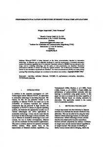
The most favorable topology in automation systems is line topology (Fig. 3a). This topology is one of the most efficient topologies in EtherCAT as shown in [1] and [2]. However, because of the logical ring topology, EtherCAT communication efficiency is significantly reduced in case of networks with large number of devices. In order to improve it, some of the optimization measures must be carried out. Basically, there are two possible approaches. 35
M. Knežić, B. Dokić, Ž. Ivanović
The first approach is based on the organization of the devices in physical linear topology with symmetrical spatial distribution of inputs and outputs. In this way, frame transmission time (which consumes the major part of the cycle time) can be reduced up to 50% in comparison to the non-symmetric distribution [10]. One such solution with automated network configuration was described in [11]. However, this approach does not always lead to the feasible solution. There are cases when symmetry cannot be achieved (e.g. network that contains only inputs). The second approach is based on parallelization of the EtherCAT logical ring using conventional switches (breaking the physical line using star topology as shown in Fig. 3b). This means that one logical ring is broken in several smaller logical rings (having smaller propagation time) that deliver data in parallel. In this way, network propagation time is reduced by k times (where k = n m is the number of switch’s port). Despite the fact that breaking the one logical ring into several smaller rings increases frame transmission time, this can be neglected in case of large number of devices. Given approach is known as the Switched EtherCAT technology and is described in detail in [12].
(a)
(b) Fig. 3 – Different topology options in EtherCAT networks: (a) line and (b) switched topology.
Since EtherCAT slaves do not evaluate MAC addresses, for correct EtherCAT frames distribution some mechanism inside switch must be implemented. For this, managed switches with VLAN tagging option can be used. These switches are easily configured to forward EtherCAT frames from master to the designated EtherCAT segment. In this way, special EtherCAT couplers with MAC filtering option can be left out. Implementation of the Switched EtherCAT requires only software modifications on the master. 36
Performance Evaulation of the Switched EtherCAT Networks with VLAN Tagging
4
Performance Evaluation
Performance analysis is based on the calculation of the minimum communication cycle time in Switched EtherCAT network. This time is defined as the time necessary for the exchange of input/output data between the controller and all networked devices once [4] and is highly influenced by the network topology. The word “minimum” here does not refer to the minimum network latency but rather the fact that time needed by controller to process inputs and generate new outputs is not considered in these calculations. It just indicates the communication capability of the actual network technology used for realization of the system. Hence, this is the minimum cycle time that could be achieved in the communication system if processing time in the controller would be zero. Total communication cycle time is given by the following equation: TCycle = TFrame + TNetwork . (1) The first part ( TFrame ) is referred to as frame transmission time and can be calculated with the following equation: 8L TFrame = Frame , (2) bw where: LFrame – size of the frame being transmitted (in bytes) and bw – network bandwidth (in bits per seconds). For logical addressing, LFrame can be calculated as [1]:
⎛ ⎞ ⎡ np ⎤ LFrame = max ⎜ np + ⎢ (3) ( hE + hECAT + hD + hwkc ) , Lmin ⎟ , ⎥ ⎢1486 ⎥ ⎝ ⎠ where: n – number of devices, p – payload per slave device (in bytes), hE − Ethernet header (including VLAN tag), hECAT – EtherCAT header, hD − datagram header, hwkc – working counter, Lmin – minimum sized Ethernet frame with VLAN tagging option (68 bytes excluding Preamble and Interframe gap). The second part ( TNetwork ) in (1) is due to the network propagation time and for line topology it can be calculated as: TNetwork = 2nTCable + nTSlave , (4) where: TCable – propagation delay introduced by cable between slave devices (about 5 ns per meter of cable length) and TSlave – average forwarding time of the slave device. In case of Switched EtherCAT, network propagation time is reduced because one long segment in line topology is replaced with k segments that 37
M. Knežić, B. Dokić, Ž. Ivanović
contain smaller number of slave devices, but it contains additional delay introduced by switch device ( TSwitch ) and cable ( TCable ) used for connecting the master device with the switch TSwECAT = 2 (TSwitch + TCable ) . (5) In (5), TSwitch and TCable delays are multiplied by two because the processing of the frame in switch takes place in two directions (direct and returning path). When (3) is taken into account, equation (4) for Switched EtherCAT becomes TNetwork = 2mTCable + mTSlave + TSwECAT , (6) where m = n k is the number of slaves in each branch of the switch device (assuming that each branch consists of the same number of slaves). Propagation delay of the switch device ( TSwitch ) depends on the switch type. For cut-through switches, this delay is constant and is about 3 μs [12]. In case of store-and-forward switches, propagation delay depends on frame size and can be calculated as TSwitch = TFabric + TStore + TQueue (7) where: TFabric – delay introduced by internal logic of the switch (in modern switches the typical value of this delay is about 5.2 μs [13]), TStore – time needed for storing the frame received by switch, TQueue – queuing time in case of frame buffering due to forwarding port busy condition which depends on the network load. Storing time ( TStore ) depends on length of the frame received by switch and can be calculated using (2) and (3). In properly configured networks, TQueue can be considered to be zero.
5
Results and Discussion
By using equations derived in the previous sections, we have performed the number of simulations using Matlab software package. The following assumptions were introduced: – average Ethernet cable length between slave devices is 10 meters, – average payload per slave device is 8 bytes, – maximum number of slave devices is 1000, – average forwarding time of the slave device is 1.2 μs (typical value for off-the-shelf slave devices [1, 2]), – network is properly configured so it can be assumed that TQueue = 0 , – logical addressing is used, – for segmentation of the line topology one 8-port switch is used.
38
Performance Evaulation of the Switched EtherCAT Networks with VLAN Tagging
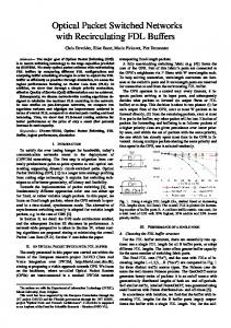
The minimum communication cycle time as a function of the number of slave devices is shown in Fig. 4. The number of slaves was changed in the range from 1 to 1000 (large EtherCAT networks).
Fig. 4 – Minimum cycle time in μs as a function of the number of slave devices.
As can be seen from the figure, Switched EtherCAT benefits in terms of minimum cycle time for a large number of slave devices (both cut-through and store-and-forward switches). The advantage over the line topology goes above 50% in case of large networks (for number of slaves greater than 500). The line topology has advantage only when number of devices does not exceed 54 for store-and-forward and 35 for cut-through switches. To address the impact of the port numbers of the switch device, we performed the simulations for a scenario where number of ports was changed in the range from 4 to 64. Obtained results are shown in Fig. 5. From the Fig. 5, it can be seen that the advantage of the Switched EtherCAT decreases with the increase of port numbers. In that way, for 64-port cut-through switch, line topology has advantage for a number of slaves less than 235. Also, when the same figure is observed respecting the number of ports for a constant number of devices (Fig. 6), it can be concluded that there is a local minimum between 10 and 20 ports. By increasing the number of ports, cycle time becomes greater and communication efficiency is reduced. 39
M. Knežić, B. Dokić, Ž. Ivanović
Fig. 5 – Minimum cycle time in μs as a function of number of slave devices and ports.
Fig. 6 – Influence of number of ports on the communication efficiency.
40
Performance Evaulation of the Switched EtherCAT Networks with VLAN Tagging
6
Conclusion
In this paper performance analysis of the Switched EtherCAT solution with VLAN tagging was conducted. It was shown that, in case of large networks, communication efficiency of the EtherCAT can be optimized in terms of minimum communication cycle time using proposed solution. Analyzing the simulation results, we have concluded that the optimal efficiency is achieved using switches with number of ports between 10 and 20. Switched EtherCAT is a simple solution which does not require hardware changes in off-the-shelf components. On the other side, there are many aspects that are not covered by the previous analysis, such as synchronization issues, implementation of redundancy, automated network configuration, etc. In certain conditions, some of the problems can be overcome, but in real-life applications these requirements are usually of crucial importance. Although it is a cheap solution regarding the hardware requirements, Switched EtherCAT still requires serious software modifications on the master side that imply the need of designing the new algorithms for configuration of the EtherCAT networks.
7
References
[1]
M. Knezic, B. Dokic, Z. Ivanovic: Topology Apsects in EtherCAT Networks, Power Electronics and Motion Control Conference, Ohrid, Macedonia, 6 – 8 Sept. 2010, pp. T1-1 − T1-6. M. Knezic: Contribution to the Performance Analysis of the EtherCAT System based on Communication Cycle Time, Master Thesis, University of Banja Luka, Faculty of Electrical Engineering, Dec. 2010. (In Serbian). IEC 61784-2 Standard, Digital Data Communications for Measurements and Control – Part 2: Additional Profiles for ISO/IEC 8802-3 based Communication Networks in Real-time Applications, International Electrotechnical Commission (IEC), Nov. 2007. J. Jasperneite, M. Schumacher, K. Weber: Limits of Increasing the Performance of Industrial Ethernet Protocols, Conference on Emerging Technologies and Factory Automation, Patras, Greece, 25 – 28 Sept. 2007, pp. 17 − 24. D. Diedrich, P. Neumann, H. Schweinzer: Fieldbus Technology, Springer-Verlag, Germany, 1999. G. Cena, S. Scanzio, A. Valenzano, C. Zunino: A Distribute-merge Switch for EtherCAT Networks, IEEE International Workshop on Factory Communication Systems, Nancy, France, 18 – 21 May 2010, pp. 121 – 130.
[2]
[3]
[4]
[5] [6]
[7] [8]
[9]
IEEE Std. 802.1Q-2005, IEEE Standard for Local and Metropolitan Area Networks − Virtual Bridged Local Area Networks, May 2006. M. Knežić, B. Dokić: Performance Aspects of the Switched EtherCAT Networks, 55th ETRAN Conference, Banja Vrućica, Bosnia and Herzegovina, 6 – 9 June 2011, pp. EL2.3-1 − EL2.3-4. (In Serbian). EtherCAT Specification – Part 3: Data Link Layer Service Definition, EtherCAT Technology Group (ETG), March 2009.
41
M. Knežić, B. Dokić, Ž. Ivanović [10] M. Knežić, B. Dokić, Ž. Ivanović: Influence of the EtherCAT Frame Transmission Time on Network Efficiency in Case of Asymmetric Traffic, 54th ETRAN Conference, Donji Milanovac, Serbia, 7 – 10 June 2010, pp. EL4.1-1 − EL4.1-4. (In Serbian). [11] M. Knezic, B. Dokic, Z. Ivanovic: Increasing EtherCAT Performance using Frame Size Optimization Algorithm, IEEE International Conference on Emerging Technologies and Factory Automation, Toulouse, France, 5 – 9 Sept. 2011, pp. 1 − 4. [12] G. Cena, S. Scanzio, A. Valenzano, C. Zunino: Performance Analysis of Switched EtherCAT Networks, IEEE International Conference on Emerging Technologies and Factory Automation, Bilbao, Spain, 13 – 16 Sept. 2010, pp. 1 − 4. [13] Latency on a Switched Ethernet Network – Application Note, RuggedCom – Industrial Strength Networks, Ontario, Canada, 2008.
42