Performance Improvement with Circuit-Level Speculation Tong Liu and Shih-Lien Lu Intel Corporation
[email protected];
[email protected]
Abstract Current superscalar microprocessors’ performance depends on its frequency and the number of useful instructions that can be processed per cycle (IPC). In this paper we propose a method called approximation to reduce the logic delay of a pipe-stage. The basic idea of approximation is to implement the logic function partially instead of fully. Most of the time the partial implementation gives the correct result as if the function is implemented fully but with fewer gates delay allowing a higher pipeline frequency. We apply this method on three logic blocks. Simulation results show that this method provides some performance improvement for a wide-issue superscalar if these stages are finely pipelined.
1. Introduction The performance of microprocessor has been accelerating rapidly in recent years. This gain has been achieved through two fronts. On one front, microarchitecture innovations have been able to take advantage of the increase number of devices to process more useful instructions per cycle (IPC). Superscalar is the predominant scheme used. A superscalar processor issues multiple instructions and execution them with multiple identical function unit. It employs dynamic scheduling techniques and executes instructions out of the original program order. The main goal is to exploit as much instruction level parallelism as possible in the program. On the other front, the miniaturization of devices improves layout density and makes the circuits run faster since electrons and holes need only to travel shorter distance. Clever circuit techniques have also been invented to further speed up the logic. Together with finer pipestages, modern microprocessor has accelerated its frequency greatly in recent years. However, it is believed more complexity is necessary to continue the exploitation of parallelism. This complexity increase tends to cause more circuit delay in the critical path of the pipeline, thus limiting the frequency to go up further. The current approach is to allow logic structures with long delays to spread over multiple pipe-stages resulting in structures that complete the computation in
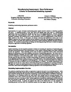
single pipe-stage previously to take more than one cycle. However, finer pipelined machine leads to longer pipeline latency and imposes higher penalty due to branch missprediction and miss-speculation. Moreover, other instructions that depend on the results of these multistaged functional blocks will have to wait until they finish in order to move forward in the pipeline. Figure 1 illustrates the effect of executing consecutive dependent instructions. Therefore, these long delay structures may become the performance bottleneck of microprocessor as clock frequency continues to rise in the future. Thus, one of the essential challenges in achieving performance in future microprocessors is the ability to increase IPC without compromising the ever-increasing clock frequency. Much work had been devoted to finding methods to increase IPC. One possible approach is to increase the width of the superscalar processor [1-6]. Another approach considered by many researchers is multi-threading [7-12]. Both methods tend to increase the size of the structures used internally such as instruction window and re-orderbuffer. Larger size means longer delay and may affect the growth in clock frequency. Work done by Cotofana and Vassiliadis [13] identified the delay complexity of issue logic in a superscalar processor to be a function of issue IF
ID
EX
EX
M
W
IF
ID
EX
EX
M
W
IF
ID
EX
EX
M
W
IF
ID
EX
EX
M
W
(a) Pipeline with Independent Instructions IF
ID
EX
IF
ID
IF
EX
M
W
EX
EX
ID
IF
ID
M
W
EX
EX
M
W
EX
EX
M
W
(b) Pipeline with Dependent Instructions Figure 1. Example of Dependent and Independent Instructions Pipeline Execution
width. Work by Palacharla et. al. [14, 15] concluded that possible clock limiting structures in a
superscalar processor include, register rename logic and issue logic. Also as the machine data and address width increases (currently moving from 32 to 64 bits), we believe adder may also become a bottleneck limiting the increase in frequency because many groups reporting the design of high performance microprocessors include their add circuits in their papers [16-18]. This suggests that adder may limit the frequency of microprocessor if we want to have finer pipeline stages in the future. In this paper, we propose to use circuit level “prediction” to “speculate” the output of critical logic blocks. The approach calls for a simpler and faster circuit implementation to approximate the original complex function. We termed this technique approximation. Approximation circuit should be designed so that it produces the correct result most of the time. Since it is not 100% correct it does require a way to verify the correctness of the approximation. A duplicated logic block, which implements the true function and samples the output at the original worst case delay is used for verification. Results from the approximation and verification blocks are compared to determine if the approximated result used to advance the pipeline is correct or not. When the comparison result is negative we kill the instruction and use the correct result to continue. The recovery mechanism is similar to what is reported in [19]. A modified SimpleScalar [20] tool set in section is used to compare performance.
2. Background and Baseline Design The logic structures we have considered are adder, issue logic and register rename logic. Adder circuit delay is not related to issue width. However address calculation done by integer adder is the key operation for instruction fetch, branch prediction and data supply from memory [21]. Moreover, we are observing a trend in the growth of datapath width. Currently we are in transition from 32 bits to 64 bits. Designing very fast large adder has been a constant research topic [22, 23]. The latter two are key structures used to exploit ILP in a wide-issue superscalar microprocessor and generally considered as single cycle function logic that are proved to be difficult to pipeline inside. We called these structures cycle limiter. In order to compare performance improvement, a baseline microarchitecture is needed. There are different ways to implement an out-of-order superscalar. Our baseline uses a centralized issue window, which combines the reorder buffer and instruction window together, and can provide precise interrupt [1, 14, 24].
2.1. Adder Many instructions contain add. Load, store and branch use adder for address calculation. Arithmetic instructions
use adder for add, subtract, multiply and divide. There are many different kinds of adders. Due to performance requirement, most of the current high performance processors employ one of the known parallel adders [25]. These parallel adders, such as Carry Look Ahead (CLA), Brent-Kung Adder (BKA), Kogge-Stone Adder (KSA) and Carry Select Adder (CSA), all have comparable asymptotic performance [26] proportional to log (N), where N is the number of bits of the adder. The cost complexity of parallel adders approaches N 2 when fan-in and fan-out of gates used are fixed.
2.2. Register Rename Logic Register renaming eliminates storage conflicts (antiand output dependencies). When an instruction is decoded, its destination register is assigned to a physical register (renamed). Usually the number of physical registers is greater than the number of architectural or logical registers. When a later instruction refers to a previously renamed destination register (with its logical binding), it must be able to traverse the renaming and obtains the value stored inside the corresponding physical register or just the tag of the physical register if the value has not yet been produced. Thus, the register rename logic is used to translate logical register designators into physical register designators and is accomplished by accessing a mapping table with the logical register designator as the index. From [14, 15], there are two different implementations: RAM and CAM. In the RAM scheme, the number of entries (i.e., rows) in the mapping table is equal to the number of logical registers and is independent of the number of physical registers. However the mapping table’s entry length (i.e., columns) of the RAM scheme depends on the number of checkpoints needs to be stored. As we issue more instructions per cycle we need to predict over nested branches that will increase the width of the mapping table. The CAM scheme, on the other hand, has fixed table width but requires a larger number of entries. We use the CAM structure in our baseline machine. A block diagram of the renaming logic is shown in Figure 2 (in this figure the horizon entries are rows). It consists of a set of physical registers, a mapping table and a priority encoding logic block. The number of entries in the mapping table is equal to the number of physical registers. When a decoded instruction enters into the rename logic, its destination register is assigned a new entry in the physical register and the corresponding physical register is stored with the logical register binding. The same decoded instruction’s source registers binding will be used to lookup the mapping table associatively. Since it is possible that a logical register can match multiple physical registers due to earlier instructions specify the same destination registers, the result from this associative lookup is channeled into the priority encoding logic. The priority
encoder converts the multiple ones into a single active line to be used to access the physical register. The critical path Physical register
Most recent Match Priority logic 1
Rk
Multiple matches . . . Rename CAM
R3 R5 R2 R3 R5 R2 P0 P1 P2 (rows)
. . . . . .
R2 R4 R6 Pn
Figure 2. Rename CAM and priority logic, R is logical register, and P is physical register
of register rename using this scheme is the time for mapping table lookup and the priority encoding logic when multiple matches are found. In the worst case, when the matched entry is at the head of the mapping table, Nbit adder-like ripple structure will be formed through the entire priority encoder. A carry look ahead structure (parallel-prefix) can be used and the delay will be in the order of log (N), where N is number of physical registers.
2.3. Instruction Issue Logic The issue logic contains three different parts, and all of them are speed critical [13, 14, 15]. When an instruction is finished from the functional unit, it writes result back to its destination register. Status of its dependent instructions will be updated by broadcasting the tag associated with the result register to all the instructions in the issue window. If there is a match that particular operand is marked ready. If all operands of an instruction are marked ready, it is ready to be issued. If multiple dependent instructions are ready to issue, there may be contentions on issue bandwidth and functional unit. A selection logic is needed to arbitrate which ready instruction to be issued first. There are different kinds of selection policy, and oldest-first policy, which grant instruction occurs earliest in program order first, is one of most popular policies. In a superscalar machine, since out-of-order issued instructions usually retire in-order, this policy is necessary because issuing old instruction first can resolve dependency quicker and committing earlier instruction first can leave space in the instruction window for newly decoded instructions. When a ready instruction is granted to issue, writeback data of the instruction it depends on will be bypassed from output of the corresponding functional unit to the source register. The delay of wakeup-selection-bypass logic increases with increasing issue window size. The selection logic will start to check the request of instructions from earliest to latest in program order, which is the order of RUU [28] from head to tail. In the worst case, when the only request is
from tail of RUU, an adder like ripple carry will be formed through all entries of RUU. A carry look ahead structure can be used to make this process parallel and the delay is the order of log (N), where N is the window size. For wakeup and bypass logic, the RC delay dominates the circuit speed. Circuit simulation shows that RC delay is more sensitive to window size than logic gate level [14]. For the multiple issue case, the delay analysis will be similar.
3. Circuit Level Speculation Previous study [29] shows that for random input data, the average carry length of a CLA is only 1/3 of its data length. Moreover, other works have shown that there is redundancy exits in programs [30-32], i.e., many instructions perform the same computation with similar input data pattern repeatedly. This could be used for adder output speculation. For example, in address calculation, one of the input to the adder is static. Moreover the other operand is usually incrementing with a regular stride. Therefore the actual adder delay is much shorter than the worst case maximum delay. We use the approximation technique described in the introduction section by generating a part of the whole carry chain. As for the register renaming logic, we believe that the renaming will mostly happen among instructions close to each other, so we employ the approximation method described previously and use a simpler priority encoding logic. For issue logic, we only select among a small group of instructions close to the head of instruction queue to issue. Due to this selection strategy, the wakeup and bypass logic can be prioritized to work on the corresponding instructions closer to head of instruction queue first, and work on the rest of instructions later. Because of the approximation techniques, the total pipestages of machine are shorter, the dependency chain will be resolved faster, and results in higher IPC. As other prediction methods, circuit level value prediction is not 100% accurate. If the prediction is wrong, the false speculated instruction has to be re-issued and re-executed. This will cause more resource contention, and dependency chain will be resolved even slower than the baseline structure. If the prediction accuracy goes down to a certain point, the speculatively architecture will perform worse than the baseline architecture. So we can only work on the logic structure whose behavior is highly predictable. If the prediction accuracy is high enough to overcome the replay penalty of false speculation, the performance improvement is expected. Also the wrongly speculated instruction output will trigger its dependent instructions to start execution and produce more false result. These false results will trigger their own dependent instructions to execute, and cause a chain reaction resulting in large overhead and overall performance loss. Therefore it is
important to stop the write-back of the speculative instructions as soon as the false prediction is detected. We describe the details of our design and analysis used in the following sections.
3.1. Adder The critical path of an adder is its full carry chain. For an N-bit adder, we denote the individual bits of the two input operands as ai, bi and intermediate carries as c i (i=0, …, N-1). Each intermediate carry signal - c i depends on all its previous input bits. i.e., ci = f(ai-1, bi-1, ai-2, bi-2, …, a0, b0) Thus, in order to generate the correct final result, we must consider all input bits (look ahead all inputs) to obtain the final carry out. However in real programs, inputs to the adder are not completely random and the effective carry chain is much shorter for most cases. Our approximated design considers only the previous k inputs (lookahead kbits) instead of all previous input bits for the current carry bit. i.e., ci = f(ai-1, bi-1, ai-2, bi-2, …, ai-k, bi-k) where 0 < k < i+1 and aj, bj = 0 if j