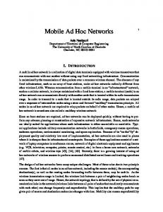
immediately when the channel has been idle for SIFS after the ACK has been returned to the sender. Fig. 1 shows the DCTF frame exchange in the RTS/CTS ...
Performance Improvements of Integrating Ad Hoc Operations into Infrastructure IEEE 802.11 Wireless Local Area Networks Zhanping Yin and Victor C.M. Leung* Dept. of Electrical and Computer Engineering The University of British Columbia 2356 Main Mall, Vancouver, BC, Canada V6T 1Z4 {zhanping, vleung}@ece.ubc.ca * Corresponding author: Tel: +1-604-8226932; Fax: +1-604-8225949
Abstract: In the infrastructure configuration, the standard IEEE 802.11 wireless LAN employs an access point (AP) to forward all packets regardless of their destinations, resulting in significant system performance degradation in terms of throughput and packet delay when a significant portion of packets have intra-cell destinations. These intra-cell packets could be more efficiently delivered to the destinations directly in an ad-hoc manner. In this paper, we propose methods to seamlessly integrate such ad-hoc operations into the infrastructure mode. By inserting a 2β delay in the frame exchange sequence, the proposed 2β Ad-hoc Awareness Direct Connection (2β AHADC) scheme brings ad-hoc awareness to the infrastructure setting and minimizes the number of packets forwarded by the AP. Furthermore, a Direct Cut-Through Forwarding (DCTF) scheme is introduced to minimize the intra-cell packet forwarding delay. We evaluate the performance of the proposed methods by theoretical analysis and simulations. Numerical results show that in systems with significant fraction of intra-cell packets, the DCTF and 2β AHADC schemes effectively reduce packet delays and increase system throughput. The proposed methods extend the capability and performance of existing standards in a backward compatible manner, by introducing minor modifications that do not require explicit mode switching or extra modules. Keywords: WLAN, 802.11, infrastructure, ad hoc
1
1. Introduction Applications of IEEE 802.11 wireless local area networks (WLANs) have expanded rapidly in recent years and become one of the focal points of the wireless services industry. The basic medium access mechanism in IEEE 802.11 is the distributed coordination function (DCF), which is a random access method based on carrier sensed multiple access with collision avoidance (CSMA/CA) and binary exponential backoff for collided packet retransmissions [1]. DCF defines a basic access method with two-way handshakes as well as an optional four-way handshake method by exchanging request-to-send and clear-to-send (RTS/CTS) control frames. Most of WLANs deployed today are configured to operate in the infrastructure mode, where central nodes called access points (APs) are employed to provide access to the distribution system (DS) by forwarding all packets to and from the cells, each one under the radio coverage of an AP. The AP is normally used to provide Internet access for the associated stations in a WLAN. However, with the wide adoption of WLANs in enterprises, offices and even homes, more and more WLANs are used to totally replace the wired LANs such that network servers may also be connected via the WLANs. For the purpose of accessing the WLANs, servers and clients are all considered as indistinguishable wireless stations. Besides accessing the Internet via the APs, many stations also need to exchange data among themselves, e.g., clients accessing the local network servers, and peer-to-peer file and stream transfers among users. Therefore, intra-cell packets, which sources and destinations are stations within the same cell, could represent a significant fraction of the WLAN traffic in these scenarios. However, in the infrastructure configuration of IEEE 802.11 WLANs, the MAC protocol assumes that all packets are sent to or from the AP in each cell. As a result, the AP has to forward all intra-cell packets even if both source and destination stations are within radio range of each other. Therefore, the
2
infrastructure mode is very inefficient for delivering intra-cell packets. Furthermore, the AP becomes the bottleneck of the system and requires a big buffer size to store the forwarding packets. In the presence of heavy intra-cell traffic, the forwarded packets would experience long queuing delay or be dropped due to buffer overflow, which could lead to undesired packet retransmissions. Moreover, as the congregated traffic at AP results in unbalanced traffic load, service differentiation techniques need to be implemented to ensure traffic fairness. Therefore, if the intra-cell packet ratio is high, a WLAN operating in the infrastructure mode could experience severe performance degradation. For an intra-cell packet, if its source and destination can communicate directly with each other, direct delivery under the ad-hoc mode of IEEE 802.11 would be a better choice. However, the current IEEE 802.11 standard does not allow a station to operate simultaneously in both the ad hoc and infrastructure modes. In a pure ad-hoc network, if the destination is out of the range of the source station, the packet cannot be delivered directly but needs to be forwarded towards the destination using an ad-hoc routing process at the IP layer, which increases traffic load in the system and incurs extra delay for packet delivery. On the contrary, in the infrastructure mode no IP layer routing is required within the WLAN as the APs forwards for all packets over the DS. As the DS usually also provides access to a router, the infrastructure mode is the most common configuration that enables stations to access the Internet beyond the WLAN. Therefore, to improve the overall system performance, an integration of infrastructure and ad-hoc operations is desired. Moreover, the current MAC protocol in 802.11 DCF has not been designed to efficiently accommodate packet forwarding operations in that a received packet will need to undergo another round of contention when it is being forwarded. Thus an efficient packet forwarding technique can further enhance the system performance by reducing the forwarding delay for
3
intra-cell packets. There are many research works on IEEE 802.11 protocols. The throughput and delay performance of 802.11 DCF has been extensively studied in the literature [2–6]. Several methods have been developed to adjust the protocol to achieve its theoretical saturation throughput [7–10]. However, none of these investigations have specifically taken into account of forwarding of intra-cell packets. In [11], the intra-cell packet problem is studied and a mixed-mode solution is proposed, in which extra mode switching control and channel management modules are introduced and need to be added above the current standard. This paper presents a novel solution to transfer intra-cell packets by integrating ad hoc operation into the infrastructure mode in a manner that is backward compatible and does not require explicit mode switching. Our solution includes a 2β Ad-hoc Awareness Direct Connection (2β AHADC) scheme and a Direct Cut-through Forwarding (DCTF) scheme. The 2β AHADC scheme allows all intra-cell packets to be received by the most efficient method; i.e., if the destination is directly reachable, the packet is received directly in ad-hoc mode by the destination station, otherwise, the packet is forwarded by the AP as normal. This is achieved by inserting an extra 2β (where β represents the maximum propagation delay in the WLAN system) delay into the packet exchange sequence, so that the AP can sense whether the destination station responds to indicate successful direct delivery, and if not, forward the packet normally. For further enhancement, the DCTF scheme is introduced at the AP to minimize the packet forwarding delay of intra-cell packets that cannot be directly delivered, by eliminating access contention and immediately forwarding intra-cell packets after a short inter-frame space (SIFS). While the 2β AHADC scheme and the DCTF scheme can be deployed separately, our performance evaluations show that the combination of both techniques can yield substantial
4
performance gain in both system throughput and packet delay. The rest of the paper is organized as follows: Section 2 presents the proposed schemes and the modifications required on the current standard. Section 3 first derives the direct connection probability for a random intra-cell packet, and then gives a theoretical analysis on the different schemes. Analytical and simulation results are presented in Section 4 followed by conclusions in Section 5. 2.
The proposed schemes
2.1. Direct cut-through forwarding medium access scheme To minimize the intra-cell packet delay due to packet forwarding at the AP, we propose the DCTF scheme. In [12], a Data-Driven Cut-Through Medium Access (DCMA) method is proposed for multihop IP packets in IEEE 802.11 networks, which generates acknowledgment (ACK) and RTS packets to the next hop. While it is advantageous for multihop forwarding, DCMA is not optimized for packets forwarding in the infrastructure setting. Since a packet sent by an AP can be sensed by all stations in the cell, there is no need for another RTS/CTS exchange when forwarding the packet. Therefore, to minimum the intra-cell packet forwarding delay, instead of waiting for another CSMA/CA backoff contention process or performing another RTS/CTS exchange, the DCTF scheme forwards the packet to its destination immediately when the channel has been idle for SIFS after the ACK has been returned to the sender. Fig. 1 shows the DCTF frame exchange in the RTS/CTS access method for an intra-cell packet transmission. The same principle holds for the basic access method. The DCTF scheme can be employed independently or be implemented together with the 2β AHADC scheme described below. 2.2. 2β Ad-Hoc Awareness Direct Connection (2β AHADC) Scheme
5
The 2β AHADC scheme brings ad-hoc awareness to the infrastructure mode and forms a seamless integration. Considering the broadcast nature of wireless transmissions, a packet can be sensed and received by all nodes within the sender’s coverage. So a direct connection is preferred whenever the sender and receiver pair is within radio range. The 2β AHADC scheme introduces a 2β delay into the packet exchange sequence to let the AP sense if directly delivery of a packet to the destination is possible. If the AP receives an ACK from the destination station, it knows the packet has been delivered successfully in ad-hoc mode. Otherwise, no response from the destination stations after the 2β delay implies that the destination station is out of the transmission range of the sender. Instead, the AP then replies to the sender with an ACK to continue the packet delivery process by forwarding the packet to the destination. Consequently, the purposed scheme fully utilizes available direct connections for intra-cell packets and delivers them in the most efficient manner, thus increasing the effective system throughput and reducing the average packet delay. In order to integrate the ad-hoc operations into the infrastructure mode, some minor modifications are required relative to the current standard. However, no explicit mode switching is required and the modified scheme is fully compatible and interoperable with existing standards. We describe the changes based on the RTS/CTS method, followed by a brief comment on the basic access method. In the IEEE 802.11 DCF, all stations contending for medium access perform binary exponential backoff when the channel is sensed busy or the station’s transmission has suffered a collision. When a station gets to access the channel, it first sends an RTS and waits for the CTS before it actually sends the data. In the infrastructure mode, the Receiver Address (RA) field in RTS is always set to the AP address except for broadcasting packets and packets sent by the AP.
6
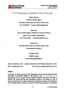
When the RTS is received, the receiver replies with a CTS frame after an SIFS delay. The sender then sends the DATA packet SIFS after the CTS is received. Finally, the receiver sends an ACK back SIFS after the DATA is received, and the channel needs to stay idle for DCF inter-frame space (DIFS) after ACK before it is ready for access contention again. The formats of RTS, CTS and ACK frames are shown in Fig. 2. After the AP receives a DATA packet, it checks the addresses in the frame header. If it is not the final destination, the AP will forward the DATA packet to its destination. For an intra-cell packet, it needs to be saved in the MAC queue of the AP, waiting for another contention process to be forwarded in the wireless channel. Assume that all terminal stations in the WLAN cell are associated with the AP and their addresses are recorded in the AP's database, and the AP can sense the channel busy immediately after an associated station starts sending a packet. Also, we consider that the AP broadcasts the list of associated stations periodically and whenever an association and/or de-association occurs so that all associated stations have an updated copy of the list of MAC addressed associated with the service set. The only additional modification required in the proposed 2β AHADC scheme is the RA fields in the RTS/CTS frames. We describe the modifications and operations for sender, receiver and the AP respectively in the following paragraphs. Each station listens to all packets and adds the transmit station addresses of those packets it receives to the list of directly reachable stations besides the associated MAC list. When it gains access to the channel, the sender first checks the DATA packet to be sent. If the destination address (DA) is in the list of associated MAC address or the directly reachable list, the sender sets the RA field in the RTS frame with DA instead of the AP address as in normal infrastructure mode. After sending the RTS, the sender waits for the corresponding CTS, in which RA field either the DA or the AP address is acceptable. If the DA is found in the CTS, it means that the
7
destination station is directly reachable, and the DATA packet can be sent in an ad hoc manner without the participation of the AP. If the AP address is found in the corresponding CTS frame, this implies that the destination station is not directly reachable and the CTS has been sent by the AP instead. After the CTS frame is received, the sender will then send the DATA packet as in normal operation with RA field set as in the received CTS frame. Otherwise, if no CTS is received within the RTS timeout, a collision has occurred. The sender then starts an exponential backoff to access the channel again later. Fig. 3 shows the sender operations with the 2β AHADC scheme. In the standard infrastructure setting, an associated station should only receive RTS frames from the AP. With the 2β AHADC scheme, the receiver should accept all RTS frames in which the RA field is set as the receiver’s address regardless the setting of Source Address (SA). This brings ad-hoc awareness to the central controlled infrastructure setting. When receiving a frame, the receiver first checks the frame type. If frame type is CTS or ACK, since the receiver did not send RTS or DATA, it ignores the frame and defers channel access. If the frame type is RTS, the receiver first checks the RA field in it. If RA is equal to its own address, the receiver sends CTS after SIFS and then waits for the DATA as in normal operation; otherwise the receiver ignores the packet and defers channel access. In the case of a DATA packet, again the receiver first checks the RA field in its header. If RA is the same as its own address, the receiver accepts the DATA packet and returns an ACK after SIFS; otherwise, the receiver ignores the packet and defers channel access. Fig. 4 illustrates the receiver operations in the 2β AHADC scheme. As for the AP, it should listen to all RTS frames on the channel even if the DA is not set to the AP address. Since potentially the same WLAN channel could be shared by more than one
8
service sets, therefore, after a RTS is received, the AP first checks the TA and RA fields in it. If either TA or RA is not in the list of stations associated with the AP, which implies that the RTS is to or from a different service set, the AP ignores the packet and defers channel access. If TA is in the associated list, the AP then checks the RA fields in the RTS. If RA field is the AP address, it works as normal. Otherwise, since the RA is in the associated list, the AP waits for the CTS frame from the receiver for a period of SIFS plus 2β. The 2β is included to guarantee that the AP will receive the reply from the receiver if it is within the coverage of the sender. If a CTS frame is received from the receiver within SIFS plus 2β, the AP knows that the subsequent DATA packet can be delivered in ad-hoc mode, thus it leaves the process and defers channel access. Otherwise if no CTS frame is received within this period, the AP generates a CTS with RA set to the AP address and returns it to the sender. When the subsequent DATA frame is received and the DA in the DATA frame header is found among the list of stations associated with the AP, if DCTF is deployed the AP forwards the DATA frame directly after SIFS, otherwise it saves the DATA in the queue for anther channel access. Fig. 5 gives the AP operations in the 2β AHADC scheme with and without the DCTF scheme. Although the descriptions above are based on RTS/CTS access method, the same principle applies to the basic CSMA/CA access method. In this case, for the intra-cell DATA packets, instead of waiting for the CTS, the AP waits for the ACK frame from the destination for an extra 2β. If there is no ACK received within SIFS plus 2β, the AP senses that the packet cannot be delivered directly. Then the AP returns an ACK to the sender and forwards the DATA frame to its destination. 3. Performance analysis In this section, the probability that an intra-cell packet can be directly delivered to its
9
destination is first derived. Then the effective throughput and packet delay are defined as the performance evaluation criteria. Theoretical analyses are performed for the standard scheme, the proposed DCTF and 2β AHADC schemes to enable comparisons of system performance. 3.1. Direct connection probability for intra-cell packets We analyze the probability ( PDR ) that a packet within the cell can be directly delivered to the destination station. Assuming that: i) All wireless stations have the same emission power, and the transmission rates for all packets are the same; thus the coverage area of all stations are identical; ii) The associated stations are uniformly distributed within the cell; A service set is represented as a circle with the AP in the center, as shown in Fig. 6. The probability that a random intra-cell packet can be delivered directly to its destination is simply the probability that the destination station (node 2) is within the coverage of the source station (node 1) given that the destination station is within the service set of the AP. The probability that the source is located distance r from the AP is Pr(node1 at r) =
2πr 2r = πR 2 R 2
(1)
Let θ be the angle shown in Fig. 6, then
θ = cos −1 (r / 2 R) Pr(node 2 within the overlapping coverage area of node1 and AP) =
2(πR 2 (
=
2θ r r r )− R2 − ( )2 ) r R2 − ( )2 ) 2θ 2π 2 2 2 = − 2 2 π πR πR
(2) Overlap coverage area AP coverage area
(3)
Therefore, the probability that a random packet can be directly received by the destination is given by: 10
PDR =
∫
R
0
=∫
R
0
Pr(node1 at r ) × Pr(node 2 within the overlapping coverage area of node1 and AP) dr
r r R 2 − ( )2 ) 2r 2θ 2 )dr ×( − 2 2 π πR R
(4)
Evaluating this integral gives the result as 0.5865, which is surprisingly quite a high ratio. Therefore, in the standard infrastructure setting, the AP forwards a big portion of intra-cell packets that can actually be received directly by their destinations. Thus, huge performance enhancement can be expected by integrating ad-hoc operations into the infrastructure setting. 3.2. Performance analysis model and evaluation criteria Since the AP needs to deal with the congregated packets from all other stations, service differentiation techniques should be applied to provide fairness based on traffic load. This is usually achieved by modifying one of the WLAN parameters, including the length of inter-frame space (IFS) [13–15] and the contention window size (CW) [16]. A lower value in these parameters provides the station with a high priority and better chance to access the channel. To simplify the analysis and to facilitate comparison with existing results [3, 4], we adopt another approach by starting a new contention process for each forwarded packet stream. Thus the AP can have several backoff contention processes simultaneously for different traffic flows, which is analog to several stations contending for the medium access. This approach is essentially equivalent to applying a smaller contention window size. Consider a contention window size of W, the backoff value is randomly chosen in the range of 0 to W-1, and a station transmits in a backoff slot with probability of 2/(W+1) [7]. By starting a separate backoff process, the station doubles its probability of transmission in a slot, which can be viewed as reducing the contention window by approximately one half; similarly, adding two more independent backoff processes is the same as reducing the backoff window size to around 1/3 of the original window size, and so
11
on. System throughput and average packet delay are the two most important performance criteria for WLAN systems. Using a two-dimensional discrete time Markov chain model, Bianchi obtained the saturation throughput [2, 3], which represents the maximum load that the system can carry in a stable condition. Furthermore, the expected packet delay under the same assumption is given in [4]. Extensive simulations show that the model is extremely accurate. In this paper, we extend the existing model with several redefined terms. We assume that in a centrally controlled infrastructure WLAN service set, 1) There are N stations in total including one AP and N − 1 terminal stations; 2) Among the N stations, i stations are contending for access, where i ≤ N is a random variable; 3) Among the i contending stations, j of them are sending intra-cell packets, where ( j ≤ i ) is a random variable; 4) Each of the i stations always has a packet available for transmission; 5) All packet transmissions are preceded by backoffs (i.e., the system is in saturation condition); 6) The probability p of a transmitted packet suffering a collision is constant and independent of the collisions this packet has suffered in the past; 7) There is a total number of n contention processes (this differs from [3], where n is defined as the total number of contention stations) among the contention stations and the AP; 8) α = j / i is the intra-cell packet ratio, defined as the number of intra-cell packets divided by the total number of packets transmitted by the contending stations. Applying the Bianchi model [2, 3], we obtain
12
τ=
2(1 − 2 p) (1 − 2 p)(W + 1) + pW (1 − (2 p) m )
p = 1 − (1 − τ ) n −1
(5) (6)
where τ is the probability that a station transmits in a randomly chosen time slot; W equals to CWmin , the initial contention window size; and m is the maximum backoff stage such that
CWmax = 2 m W . These two equations represent a non-linear system in the two unknown τ and p, which can be solved using numerical techniques. The system saturation throughput is given as:
S=
Ps Ptr E[ P] E[ slot ]
(7)
where E[ P ] = E[ DATA] is the expected value of the data packet payload.
Ptr = 1 − (1 − τ ) n is the transmission probability in a slot. Ps =
nτ (1 − τ ) n −1 is the probability that a transmission occurring on the channel is successful. 1 − (1 − τ ) n
E[ slot ] = (1 − Ptr )σ + Ptr Ps Ts + Ptr (1 − Ps )Tc is the expected length of a slot.
σ is the duration of an empty time slot, i.e., the backoff slot size. Ts and Tc represent the transmission periods for a successful and collided packet, respectively. The average packet delay E[D] for a successful packet, which is defined as the interval from the time the packets is at the head of the MAC queue ready for transmission until it is successfully received, is given as [4]:
E[ D] = E[ X ]E[ slot ] where E[ X ] =
(8)
1 (1 − 2 p )(W + 1) + pW (1 − (2 p ) m ) = is the average number of time slots τ (1 − p ) 2(1 − 2 p )(1 − p )
13
for a successful transmission. All these results presented assume that all packets are sent to their destination directly so that no packet forwarding by the AP is required. This can represent the case with no intra-cell packet, where all stations contend for access to send data to AP. With the default infrastructure mode, the AP tends to have higher traffic load because all intra-cell packets have to be forwarded by it. To ease analysis, instead of putting the received intra-cell packets in a single queue for future transmission, we assume that the AP starts a new backoff process for each intra-cell packet stream. As shown before, this is equivalent to assigning a smaller contention window size to the AP. Under this condition, the above throughput and delay analysis is valid only if the forwarded packets are counted separately as new packets from new contending stations. To better assess the system performance, we defined effective throughput ( S E ) and effective delay ( DE ) as the evaluation criteria. The effective throughput S E only counts the new packets sent into the system such that the forwarded packets are not regarded as effective data and will not be counted again. The effective delay DE is the average interval from the time a packets is at the head of the MAC queue ready for transmission until it is successfully received by the intra-cell destination station or the AP if the destination station is elsewhere. Thus DE includes possible forwarding time from AP to destination stations for intra-cell packets. Using these criteria, we compare the performance of the standard CSMA/CA DCF scheme against the proposed DCTF and 2β AHADC schemes. 3.3. System effective throughput and delay performance evaluation The effective throughput and packet delay are evaluated in 4 different cases: standard scheme, DCTF scheme, 2β AHADC scheme, and the combined 2β AHADC and DCTF scheme. For simplicity, a constant DATA payload is used for all packets, i.e., E[ P ] = E[ DATA] = DATA .
14
Let H = PHYHDR + MAC HDR be the packet header, then the transmitted data packet length is DATA + H. To get the throughput and delay results, the collision duration (Tc) and the time to successful reception (Ts) have to be found for these cases. As shown in Fig. 7 and the same for all four cases, the collision time (Tc) for the basic access method and the RTS/CTS access method, respectively, are given by: Tc BAS = H + DATA + DIFS + β
(9)
Tc RTS = RTS + β + DIFS
(10)
However, the time to successful packet reception (Ts) varies between the standard, DCTF scheme and 2β AHADC schemes. Since new backoff processes are created to forward intra-cell packets that cannot be delivered in ad-hoc mode, the total number of contention processes is the sum of the actual number of contending stations plus the extra backoff processes for forwarding these intra-cell packets. 3.3.1. Case 1: standard scheme with new backoff processes for intra-cell packet streams Since j of i new arrivals are intra-cell packets, thus j additional backoff processes are generated at the AP. Therefore, the total number of contention processes is: n=i+ j
(11)
As shown in Fig. 8, the time to successful packet reception is given below. Ts BAS 1 = H + DATA + ACK + SIFS + DIFS + 2β
(12)
Ts RTS1 = RTS + CTS + H + DATA + ACK + 3SIFS + DIFS + 4 β
(13)
Based on these results, the total throughput S1 and average delay E[ D1 ] for case 1 can be derived from (7) and (8). These need to be adjusted to account for the j extra intra-cell packets forwarded by the AP from among the i arrivals. Therefore the effective throughput is given by:
15
S E1 =
i 1 S1 = S1 , i+ j 1+α
(14)
Since the AP forwards each intra-cell packet with a new backoff contention process, the expected delay of each intra-cell packet is twice that of other packets. So the effective packet delay is: D E1 =
(i − j ) E[ D1 ] + j 2 E[ D f ] i
=
i+ j E[ D1 ] = (1 + α ) E[ D1 ] i
(15)
3.3.2. Case 2: DCTF scheme only With the DCTF scheme, the intra-cell packets are directly forwarded by the AP without extra contention. Thus the total number of contention processes does not change, i.e.,
n=i
(16) For packets to or from the AP, Ts remains the same as (12) and (13). But for an intra-cell
packet, an extra ( H + DATA + ACK + 2 SIFS + 2β ) delay is required for the packet forwarding by the AP, as shown in Fig. 9. Therefore, the average Ts for the system is: Ts BAS 2 =
(i − j )Ts BAS 1 + j (Ts BAS1 + ( H + DATA + ACK + 2 SIFS + 2 β )) i
= Ts BAS1 + α ( H + DATA + ACK + 2 SIFS + 2 β )
(17)
Ts RTS 2 = Ts RTS1 + α ( H + DATA + ACK + 2SIFS + 2 β )
(18)
The effective throughput and average packet delay is simply given by: S E 2 = S 2 , DE 2 = E[ D2 ]
(19)
where S 2 and E[ D2 ] are the results from (7) and (8) for case 2 with the corresponding parameters. 3.3.3. Case 3: 2β AHADC scheme only With only 2β AHADC, among the j intra-cell packets, on average jPDR packets can 16
be received directly and j (1 − PDR ) packets have to be forwarded by the AP. Therefore, total number of contention processes is: n = (i − j ) + jPDR + 2(1 − PDR ) j = i + (1 − PDR ) j ,
(20)
Among i + (1 − PDR ) j packets transmitted on the channel, on average i packets (including the j (1 − PDR ) packets forwarded by the AP to their destinations) follow the standard process. And j (1 − PDR ) packets require an extra 2β to sense that their destinations are not reachable before they are forwarded by the AP with separate contention processes, as shown in Fig. 10. Thus the average Ts for the system is: Ts BAS 3 =
iTs BAS1 + j (1 − PDR )(Ts BAS1 + 2 β ) 2α (1 − PDR ) β = Ts BAS1 + i + j (1 − PDR ) 1 + α (1 − PDR )
Ts RTS 3 = Ts RTS 1 +
2α (1 − PDR ) β 1 + α (1 − PDR )
(21)
(22)
The effective throughput and average packet delay is given by: S E3 =
i 1 S3 = S3 , i + (1 − PDR ) j 1 + (1 − PDR )α
(23)
DE 3 =
(i − j (1 − PDR )) E[ D3 ] + j (1 − PDR )2 E[ D3 ] = (1 + α (1 − PDR )) E[ D3 ] i
(24)
where S 3 and E[ D3 ] are the results from (7) and (8) with the corresponding parameters. 3.3.4. Case 4: combination of 2β AHADC and DCTF If both 2β AHADC and DCTF schemes are implemented, the total number of contention stations is the same as in DCTF scheme, i.e.,
n=i
(25)
For i packets transmitted by the stations, on average i − j (1 − PDR ) packets follow the standard process, and j (1 − PDR ) packets require the forwarding delay and the extra 2β to sense 17
that the destination is within range, i.e. an extra time of H + DATA + ACK + 2 SIFS + 4 β , as shown in Fig. 11. Thus the average Ts for the system is: (i − j (1 − PDR ))Ts BAS1 + j (1 − PDR )(Ts BAS1 + ( H + DATA + ACK + 2 SIFS + 4 β )) i = Ts BAS1 + α (1 − PDR )( H + DATA + ACK + 2 SIFS + 4 β )
TsBAS 4 =
Ts RTS 4 = Ts RTS1 + α (1 − PDR )( H + DATA + ACK + 2SIFS + 4β )
(26)
(27)
The effective throughput and average packet delay for case 4 are given by: SE4 = S4 ,
DE 4 = E[ D4 ]
(28)
where S 4 and E[ D4 ] are the results from (7) and (8) with the corresponding parameters. 4.
Numerical results and performance evaluations
The values and parameters used to obtain the numerical results are summarized in Table 1. The system values are those specified for the Direct Sequence Spread Spectrum (DSSS) PHY layer in the IEEE 802.11 standard [1]. The packet payload assumes a constant size of 1024 bytes with the channel bit rate at the base rate of 1 Mbits/s. We first verify the analysis of the direct connection probability PDR by simulations, in which a large number of pairs of points within a circle of radius R (where R is arbitrary) are generated at random and the distance between them computed. If the distance is smaller than R, a direct connection exists, and vice versa. The simulation result verifies the analysis in section III, i.e., PDR = 0.5865. To verify the delay-throughput analyses in section III, a simulation program written in C++ was developed to evaluate the throughput and delay of the four schemes by simulations. In these simulations, instead of simulating the physical location of each station, for simplicity the probability of direct delivery of intra-cell packets, PDR =0.5865, was applied to each packet
18
transmitted in the 2β AHADC scheme. Each data point was obtained by sending 5 million DATA packets. To further verify the simulation program, the system effective saturation throughput with RTS/CTS access under heavy traffic was also obtained using ns-2 simulations. However, the WLAN module in ns-2 is not suitable for the collection of the needed delay statistics. As shown in Fig. 12, the simulation results match the numerical results from theoretical analyses very closely. This gives us the confidence of using numerical results from theoretical analyses for further performance evaluations in the following. Fig. 13 and Fig. 14 give the effective throughput and effective packet delay results in 3-dimensional graphs for the basic and RTS/CTS access methods, respectively. Since the DCTF and 2β AHADC schemes only affect intra-cell packets, the four cases are identical if there is no intra-cell packet (α=0). Under the same scheme and conditions, the RTS/CTS access method achieves higher effective throughput and lower packet delay than the basic access method with the specified parameters. The average packet delay increases linearly with the number of stations in both access methods. At the same intra-cell packet ratio α, the effective throughput of RTS/CTS method does not change much when the number of stations increases, but that of basic access decreases dramatically. Under the same number of stations, the effective throughput declines and packet delay increases with higher intra-cell ratio α for all schemes due to an increased number of backoff contention processes from packet forwarding. Since the DCTF method eliminates all forwarding backoff processes, it greatly reduces the average packet delay. The 2β AHADC scheme utilizes the broadcasting nature of wireless transmission to enable direct delivery for intra-cell packets, thus minimizes the number of forwarded packets and achieves significantly higher throughput and lower packet delay as α becomes substantial. Best performance results are observed by employing DCTF and 2β AHADC together.
19
With the basic access method, the effective throughput decreases as the number of contention processes increases. Therefore, under the same intra-cell packet ratio, the DCTF scheme improves the effective throughput by eliminating the contention process for forwarding the intra-cell packets. The 2β AHADC scheme achieves higher effective throughput than DCTF because some intra-cell packets are delivered directly to their destinations. However, the DCTF scheme gives better results in average packet delay than the 2β AHADC scheme because the latter still needs some extra contention processes to forward the packets that cannot be delivered in an ad-hoc manner. The combination of both techniques achieves the highest effective throughput and the lowest packet delay. As an example, Fig. 15 presents the results for different number of stations with an intra-cell packet ratio of 0.4. It also shows that the effective throughput decreases and effective packet delay increases with the number of stations under a constant intra-cell packet ratio for all four schemes, but the proposed schemes always outperform the basic scheme. With a fixed number of stations, the performance gain from the proposed schemes increases with α. As an example, Fig. 16 shows the results for different intra-cell packet ratios α with 30 stations. At α=0.2, the effective throughput is increased by 3.5-9.1% using the DCTF scheme, by 12-12.9% using the 2β AHADC scheme, and by 13.6-17.3% using both techniques, compared to the standard method without these enhancements. Correspondingly, the effective packet delay is decreased by 19.5-23.6% with the DTCF scheme, 18.1-21.2% with the 2β AHADC scheme, and over 26.7-28.9% with both techniques. In the extreme case where α=1, the effective throughput is increased by 13.2-36.2% with the DCTF scheme, 47.1-51.4% with the 2β AHADC scheme, and 56.7-78.1% with both techniques, and the effective packet delay is decreased by 55.9-60% with the DCTF scheme, 52.4-53.1% with the 2β AHADC scheme, and around 68.1-71.9% with both techniques.
20
With RTS/CTS access method, the effective throughput does not change much with the number of stations. Therefore, with intra-cell packets, the DCTF scheme greatly reduces the packet delay but improves very little on the effective throughput. In contrast, the 2β AHADC scheme significantly increases the effective throughput and lowers the effective packet delay. As an example, Fig. 17 gives the results for RTS/CTS access method with different number of stations and intra-cell packet ratio equals to 0.4. It shows that with constant intra-cell packet ratio, the effective throughput with the 2β AHADC scheme is much higher than that without it, and the DCTF scheme gives only a small gain in effective throughput. As for the packet delay, the 2β AHADC scheme brings an improvement comparable to the DCTF scheme. Again, the combination of both techniques gives the best performance. Under a fixed number of stations, the performance gains from the proposed schemes become more significant with higher intra-cell ratio. Fig. 18 shows the results for different intra-cell packet ratio α with RTS/CTS access and 30 stations as an example. At α=0.2, compared to the standard scheme, the effective throughput is increased 0.3-0.7% with the DCTF scheme, 10.8-10.9% with the 2β AHADC scheme, and 11-11.3% with both techniques, and the effective packet delay is decreased by 16.9-17.2% with the DCTF scheme, 17.3-19.9% with the 2β AHADC scheme, and over 24.9-25.1% by combining both techniques. When α=1, the effective throughput is increased by 1-2.3% with the DCTF scheme, 41.6-42.1% with the 2β AHADC scheme, and 42.4-43.9% with both techniques. The effective packet delay is decreased by 50.5-51.1% with the DCTF scheme, 49.6-50.7% with the 2β AHADC scheme, and 64.9-65.2% by employing both techniques. 5.
Conclusions
In this paper, we have proposed two methods that combine to seamlessly integrate IEEE 802.11 ad-hoc operations into the infrastructure mode, which greatly improves the performance
21
of WLAN systems with intra-cell packets. The Direct Cut-Through Forwarding (DCTF) scheme significantly reduces the effective packet delay for both basic and RTS/CTS access methods. It also gives higher effective throughput for the basic access method. Utilizing the inherent broadcasting characteristic of wireless transmissions, the proposed 2β Ad-hoc Awareness Direct Connection (2β AHADC) scheme enables ad-hoc connectivity in the infrastructure mode by introducing a small delay of 2β before an AP acknowledges a RTS or DATA packet. It minimizes the number of intra-cell packets forwarded by the AP and results in substantial enhancements in both the effective throughput and effective packet delay when the intra-cell packet ratio becomes large. Best performance improvements are achieved by combining both techniques. We have derived the effective throughput and delay of the different schemes by theoretical analysis, and verify the theoretical model by simulations. Numerical results from theoretical analysis have been presented to compare the performance of the proposed schemes. In the extreme case where all packets are intra-cell, DCTF and 2β AHADC combined increases the effective throughput by up to 56.7-78.1% and 42.4-43.9%, and reduces the effective packet delay by 68.1-71.9% and 64.9-65.2% with basic and RTS/CTS access, respectively, compared to the standard scheme. The DCTF and 2β AHADC schemes are fully compatible to and interoperable with the existing IEEE 802.11 WLAN standards. Therefore the method provides an ideal solution to integrate ad-hoc operation into an infrastructure WLAN system. Furthermore, QoS enhancement methods such as EDCF [17] can be applied above our proposed method. The general principles of the proposed method can also be employed in other wireless systems, e.g., in Bluetooth to enable slave-to-slave communications among nodes within the same piconet. Acknowledgements
This work was supported in part by the Natural Sciences and Engineering Council of Canada under grant RGPIN 44289-04.
22
References
[1]
IEEE 802.11-1999, Part 11: Wireless LAN medium access control (MAC) and physical layer (PHY) specifications, 1999
[2]
G. Bianchi, IEEE 802.11: saturation throughput analysis, IEEE Communications Letters, 2 (12) (1998) 318-320
[3]
G. Bianchi, Performance analysis of the IEEE 802.11 distributed coordination function, IEEE JSAC, 18 (3) (2000) 535-547
[4]
P. Chatzmisios, A. C. Boucouvalas, V. Vitsas, Packet delay analysis of IEEE 802.11 MAC protocol, Electronics Letters, 39 (18) (2003) 1358-1359
[5]
Y. Xiao and J. Rosdahl, Throughput and delay limits of IEEE 802.11, IEEE Communications Letters, 6 (8) (2002) 355-357
[6]
Y. Xiao, Saturation performance metrics of the IEEE 802.11 MAC, in Proc. IEEE VTC’03-Fall, Orlando, FL, Oct. 2003, pp. 1453-1457
[7]
G. Bianchi, L. Fratta, M. Oliveri, Performance evaluation and enhancement of the CSMA/CA MAC protocol for 802.11 wireless LANs, in Proc. IEEE PIMRC, Taipei, Taiwan, Oct. 1996, pp. 392-396
[8]
F. Cali, M. Conti, E. Gregori, Dynamic tuning of the IEEE 802.11 protocol to achieve a theoretical throughput limit, IEEE/ACM Trans. Networking, 8 (6) (2000) 785-799
[9]
F. Cali, M. Conti, E. Gregori, IEEE 802.11 protocol: design and performance evaluation of an adaptive backoff mechanism, IEEE JSAC, 18 (19) (2000) 1774-1786
[10] D. Qiao, S. Choi, K.G. Shin, Goodput analysis and link adaptation for IEEE 802.11a wireless LANs, IEEE Trans. on Mobile Computing, 1 (4) (2000) 278-292
23
[11] J. Chen, S.H.G. Chan, J. He, S.C. Liew, Mixed-mode WLAN: the integration of ad hoc mode with wireless LAN infrastructure, in Proc. IEEE GLOBECOM '03, San Francisco, CA, Dec. 2003, pp. 231-235 [12] A. Acharya, A. Misra, S. Bansal, High-performance architectures for IP-based multihop 802.11 networks, IEEE Wireless Communications, 10 (5) (2003) 22-28 [13] K. Xu, Q. Wang, H. Hassanein, Performance analysis of differentiated QoS supported by IEEE 802.11e enhanced distributed coordination function (EDCF) in WLAN, in Proc. IEEE GLOBECOM '03, San Francisco, CA, Dec.2003, pp. 1048-1053 [14] C.T. Chou, K.G. Shin, S. ShanKar, Inter-frame space (IFS) based service differentiation for ieee 802.11 wireless LANs, in Proc. IEEE VTC'03-Fall, Orlando, FL, Oct. 2003, pp. 1412-1416 [15] G. Bianchi, I. Tinnirello, Analysis of priority mechanisms based on differentiated inter frame spacing in CSMA-CA, in Proc. IEEE VTC’03-Fall, Orlando, FL, Oct. 2003, pp. 1401-1405 [16] K. Kim, A. Ahmad, K. Kim, A wireless multimedia LAN architecture using DCF with shortened contention window for QoS provisioning, IEEE Communications Letters, 7 (2) (2003) 97-99 [17]
IEEE 802.11e draft/D4.0, Part 11: Wireless medium access control (MAC) and physical layer (PHY) specifications: medium access control (MAC) enhancements for quality of service (QoS), Nov. 2002
24
AUTHOR’S BIOGRAPHY Zhanping Yin received the B.Eng. and M.Eng. degrees in optical instrument from Tianjin
University, Tianjin, China, and the M.A.Sc. degree in electrical engineering from University of British Columbia, Vancouver, Canada, in 1992, 1995 and 2002, respectively. He is currently working toward the Ph.D. degree in the Department of Electrical and Computer Engineering, University of British Columbia, Vancouver, Canada. His current research interests are in wireless communications protocols including WLAN, WPAN and UWB. Victor C. M. Leung received the B.A.Sc. (Hons.) degree in electrical engineering from the
University of British Columbia (U.B.C.) in 1977, and was awarded the APEBC Gold Medal as the head of the graduating class in the Faculty of Applied Science. He attended graduate school at U.B.C. on a Natural Sciences and Engineering Research Council Postgraduate Scholarship and obtained the Ph.D. degree in electrical engineering in 1981. From 1981 to 1987, Dr. Leung was a Senior Member of Technical Staff at Microtel Pacific Research Ltd. (later renamed MPR Teltech Ltd.), specializing in the planning, design and analysis of satellite communication systems. He also held a part-time position as Visiting Assistant Professor at Simon Fraser University in 1986 and 1987. In 1988, he was a Lecturer in the Department of Electronics at the Chinese University of Hong Kong. He joined the Department of Electrical and Computer Engineering at U.B.C. in 1989, where he is a Professor, holder of the TELUS Mobility Industrial Research Chair in Advanced Telecommunications Engineering, and a member of the Institute for Computing, Information and Cognitive Systems. His research interests are in the areas of architectural and protocol design and performance analysis for computer and telecommunication networks, with applications in satellite, mobile, personal communications and high speed networks. Dr. Leung is a Fellow of IEEE and a voting member of ACM. He is an editor of the IEEE Transactions on Wireless Communications, and an associate editor of the IEEE Transactions on Vehicular Technology.
25
LIST OF FIGURES
Fig. 1.
The Direct Cut-Through Forwarding (DCTF) for intra-cell packets
Fig. 2.
RTC/CTS/ACK Control Frame Formats
Fig. 3.
Sender operations with 2β AHADC
Fig. 4.
Receiver operations with 2-β AHADC scheme
Fig. 5.
Access point operations with 2-β AHADC and DCTF
Fig. 6.
Direct delivery probability analysis
Fig. 7.
Collision duration for basic access and RTS/CTS
Fig. 8.
Time of successful reception for basic access and RTS/CTS in standard scheme
Fig. 9.
Time to successfully receive intra-cell packet with direct forwarding
Fig. 10.
Time to successfully receive AP-forwarded intra-cell packets with 2-β AHADC
Fig. 11.
Success time for no direct connection intra-cell packets with both optimizations
Fig. 12.
Simulation vs. theoretical results
Fig. 13.
Effective throughput and packet delay for basic access scheme
Fig. 14.
Effective throughput and packet delay for RTS/CTS access scheme
Fig. 15.
Effective throughput and packet delay for basic access with α = 0.4
Fig. 16.
Effective throughput and packet delay for basic access with 30 stations
Fig. 17.
Effective throughput and packet delay for RTS/CTS access with α = 0.4
Fig. 18.
Effective throughput and packet delay for RTS/CTS access with 30 stations
LIST OF TABLES
Table 1: System parameters used to obtain the numerical results
26
SIFS RTS
SIFS CTS
SIFS
SIFS
DATA
ACK
SIFS DATA
DIFS
Contention window
ACK
STA1 Time AP STA2 Fig. 1. The Direct Cut-Through Forwarding (DCTF) for intra-cell packets
Octets
2
2
Frame Control
Duration
6
6
RA
TA
4 FCS
Octets
2
2
Frame Control
RTS Frame Format
Duration
6 RA
4 FCS
CTS and ACK Frame Format
RTS: request to send CTS: clear to send ACK: acknowledgment
RA: receiver address TA: transmitter address FCS: frame check sequence Fig. 2. RTC/CTS/ACK Control Frame Formats
Contention for Access with Exponential Backoff
DATA DA in the associated or direct connection MAC list
If RA == DA
No
Check RA in CTS
If RA == AP
Send DATA after SIFS with RA = DA
Send DATA after SIFS with RA = AP
Wait and receive ACK from DA
Wait and receive ACK from AP
Yes If (CW