Keywords: Space-time codes, CDMA, adaptive multiuser detection. I. INTRODUCTION ..... u. (29). In the derivations of the various adaptive multiuser detectors,.
Performance of Adaptive Multiuser Detectors in Space-Time Coded CDMA Systems M. M. Alam and A. Chockalingam Department of Electrical Communication Engineering, Indian Institute of Science, Bangalore 560012. INDIA
Abstract— In this paper, we present a comparative performance evaluation of adaptive multiuser detectors, including stochastic gradient (SG) and recursive least squares (RLS) algorithms (which require training data), and minimum output energy (MOE) and subspace-based MMSE (S-MMSE) algorithms (which do not require training data), under near-far conditions in a space-time coded CDMA system. We show that, in a near-far multituser scenario, increasing the number of transmit antennas degrade the near-far resistance performance of the SG and MOE detectors significantly at high near-far ratios, to the extent that the diversity benefit of multiple transmit antennas is nullified. The RLS and S-MMSE algorithms, on the other hand, are shown to maintain their near-far resistance without loosing much on the diversity gain, when the number of transmit antennas is increased.
Keywords:
Space-time codes, CDMA, adaptive multiuser detection.
I. I NTRODUCTION It has been shown that space-time coded transmission using multiple transmit antennas can offer the benefits of transmit diversity and high data rate transmission on wireless fading channels [1],[2], which has generated lot of interest in using this technique in communication systems design (e.g., in 3G). Also, multiuser detection schemes for interference rejection, which can significantly enhance the receiver performance and increase the capacity of code division multiple access (CDMA) systems, have been extensively studied the in literature, mainly for single transmit antenna systems [3]. Investigation of multiuser detection algorithms and their performances in space-time coded systems with multiple transmit antennas has been gaining importance [4],[5]. Adaptive detectors are of interest since non-adaptive detectors require estimation of various parameters of all the users and involve matrix inversion which becomes computationally intensive as the number of users in the system (and the number of transmit antennas) increases. Our interest here is to develop adaptive receiver structures for space-time coded CDMA and evaluate their performances. We first derive a discrete-time vector model for the received signal using orthonormal projections in a space-time coded CDMA system, wherein we assume that only the timing of the desired user is known at the receiver. Using the vector model, This work was supported in part by the Swarnajayanti Fellowship, Department of Science and Technology, New Delhi, India.
we then develop the structure of various adaptive multiuser detectors with only the knowledge of the channel impulse response and the signature waveform of the desired user being available in the detection process. The various adaptive algorithms considered include the stochastic gradient (SG) and recursive least squares (RLS) algorithms (which require training data), and minimum output energy (MOE) and subspace-based MMSE (S-MMSE) algorithms (which do not require training data). We evaluate and compare the nearfar resistance performance of the above detectors. We also evaluate the convergence behaviour of the detectors in a dynamic near-far scenario, where users can randomly enter into and exit form the system. Our performance results show that the RLS and subspace-based MMSE methods offer better near-far resistance and convergence behaviour compared to the SG and MOE algorithms, when the number of transmit antennas is increased. II. S YSTEM M ODEL �
We consider a -user asynchronous CDMA system with transmit antennas per user. Users transmit frames of data blocks with � ����bits per data block. Let ����� �� , ��� ����������������� ��� ������������� � � , be the �! " bit of the �# " , ��� block of the �$ " user, transmitted in a time interval of length % � . The bits in a data block are mapped on to the transmit antennas using orthogonal space-time block codes (STBC). We assume that the channel fading is quasi-static and the �)( % quasi-static interval is � time units, where �'& , * being � the smallest integer satisfying �,+ [2]. For square real � orthogonal STBC with &-�.&-/ , the transmission matrix 0 is [1] �
45
7
5 5 5 132
5
5 6
798 7;: 7;< 79= 7;> 79? 7;@ 798BAC7 AC7;< 7;: AC7;> 79= 7;@ AC79? 7;: 7;< AC7 AC798DAC79?EAC7;@ 79= 7;> 7; 79= 79= 7;> 79? 7;@ AC7 AC798DAC7;:DAC7;< 7;>DAC79= 7;@ AC79? 798 AC7 7;< AC7;: 79?BAC7;@DAC79= 7;> 7;: AC7;DAC79= 7;< 7;: AC798 7
GIH H H H H H
(1)
JLK
In the above transmission matrix, the columns represent the transmit antenna index and the rows represent the bit interval 0 index. The transmission matrix for other real orthogonal � � designs for �EMN/ can be obtained to be the upper 0 � leftmost submatrix of of order �PO . For illustration,
�
45
�
&D� & we use for the derivation of the vector � � � � / is model. Extending the model for other values of straightforward. � � For the system, the received signal on a & � & receive antenna can be written using (1) as ������� 2 � ����� �� 8 � ��� � �� ����� (2) � � � � � � � � � � � � � % ' � % � � ��� 2 �� �����! 7 ������"$# 7 8 � �&��"$# 8)( � (3) ����� � � �� � � � � � � � � � �� 8� ����� 2 8 � 8 � ��� 7 8 �����*"+# ��% A 7 �����*"+# 8��% ( (4) ����� � � �� �)����� �
GIH
§¦ h wv�l�v 7 £ wv :¤®¤
¤
§¦ h wv�lk© 7 £ wv :¤®¤
¤ (11) . . . . . . J
¡ ¬ o 6 . . . . . . . . . . . . . ¡ . ¡ ¦ v*ª 7�£ v :
¯¦ h wv*lkª 7 £ wv :°¤®¤
¤ � �)�)� � ��������� � � It is noted ¡ that � &± � for �)synchronous �)� � ��������� � % ¡H � � CDMA, so that 6 � � L �&6 ² � L� �H� &³H N � Z , following matrices would leading to ´ &¶´ &¸· . The < < }Tµ (7) < inµ vector notation: help us to write
¹ # % � ºp� 2M» ��# % � ºp�� �0��¼ # % � ºp�½¿¾� 8 ¹c��º < � 2 » ¹ # % ¾ � ºp� �< ¹ # % < ¾ � ºp�� �0K ¹ K K #5À < % ¾ � < ºp� ½ ¾� Á � ºp� 2ÃÂ+ÄÆÅ$Ç » � ��º ��� K K � K � �8� ��º � ½ � � Á � ºp� 2ÉÈ AÁÁ 8 K K � K ºp� � ÁÁ 8 � ºp� < < � ºp� < � ºp�EÊ � Ë � ºp� 2 » 7 � ºp�� � 7 � � ºp� ½ ¾�
K
In the above, ,.- 0/ , 1 � is the signal component due to the 1 " transmit antenna, 2 �3- is the transmit amplitude on the 1 " transmit antenna of the �; " user, 4 �5- � is the complex channel gain for the �� " block from the 1 " transmit antenna of the �$ " user, and 68��7 � 9;: represents the signature waveform �)����� � of the � " user �5< for the�$= � " bit in a block, �L��F � , given by � � % 2 A A A C A B E A D " # " � �&>@? ? � (5)
energy signature waveform time limited where 6 � �/ is a unit � %JI in the interval G H , and K � is the random time delay of the �$ " user, which we assume to be independent of the transmitting antenna and to satisfy K+L +MK � for NPO � . Also, Q 0/ is a zero mean complex Gaussian noise process with ��RTS variance . �.U�V!�WU ���������WUYX � S� Let < be a set of Z orthonormal signals %[I = . Also defineF defined on G H \ ] # % ����� 2^\ ] � A A A_B ? � A 2`B � �*>a�cb 2dB � �*e (6)
K K K of the interferers KKK K may Since the signature waveforms of some not be known a priori, we project the received signal in the f " block in (3) on to the Z -dimensional space as follows: h3sutwv*lkxpy8t{z V V X gim hkj*l g � L mj (7) 7 n�:porq 7 :�| 7 w} n�~ }� :� o !
3
3
3 ~ o
3
3
3 sixpy�t8z where K is the timing of the desired user. We define the following projections of the " user’s signature waveform on to the N " component of the orthonormal basis as yp8 y m h5l� h3�tlk m h3lk��p* m h5l. h3�y�t*l m h5�l �0 (8) q q yp8 � %JI �G H " user where L . Let the � user (i.e., ����� be � ����the ����� � desired � Ku &K ) and � & K �@ K , � � � . Using (8), we define the following matrices of order Z O : 45 GIH vv 7 £ v :
§¦ v 7 } £ : ©v 7k¤¥: � v © v ©
§¦ 7 } £ : � 7 £ :
.
¡ . 7k¤¥: (9) . . ¡¨ ¨ J . . . . o 6¢¡¡ ... . . . . ¨ ¡ ¡¨ v*ª 7 £ v :
ª 7k¤¥:
«¦ ª 7 } £ : ¡ ¡ ¡¨ ¨ 45 GIH v 7 } £ : h t v*l v 7 } £ t v :
�
¤
!
¤ ¤
!.
¤ . ¡ h t v*l5© 7 . } £ t v :
.
�
¡¨ © 7 . } £ ¨ : J w¬ o 6 .. . . . . . . . . . . . ¨ ¡ ¡¨ ª 7 } £ : h t v*lkª 7 } £ t v :
�
¤
!
¤ ¨ ¡ ¡¨
¦ v v 7 £ v : ¦ v�© v ¡ .7 £ :
Ë � ºp� 2Ì»5Ë ¾ � ºp�K� K K � Ë ¾ � ºp�½¿¾ À
Using the above definitions, it can beK K K Í h5sil.aÎ w¬$Ï h3s'v*l5пh3s�v*l$tÎ Ï h5silkпh3silit�Î ¬ Ó Ó Ó » Ô Ó ¬ Õ w¬ ½ �Î » Ó Î w¬ w¬ ÖØ× Ò�h3silkÒh5sil Ù@Ú¥;©Û ©WÜ0Ý
(12) (13) (14) (15) (16) (17)
K shown that Ï h3sTtav�lkпh3s tÑv�l$t Òh5silÆ ½ �Î ¬ » Ó _½ ¬
(18) (19) (20)
The signal� model presented in (18) can be used for other � � matrices, Þ � Þrß Þ � values of , provided � we define the T } µ µ) f O-� (of order �àZ O-� ), and á� � (of order � appropriately. For example, if &-� & / , 45
GIH
Ï © Ïãâ ÏØå ÏØè H ÏÏv© ÏãÏØä â ÏãÏØæ å ÏcÏØç è Ïpä ÏØæ ÏØâ Ï Ïpv ä ÏØå ÏcÏãç æ v © Ï Ï c Ï ç ã Ï è Ï © Ïcç Ïãå ä ÏØâ Ï v ÏØè ÏØæ Ï h3sul. 6 Ïã å Ïãæ Ïcç ÏØè Ï v Ï © ÏØâ Ïãä J ÏØ © v Ø Ï æ Ø Ï å Ø Ï è c Ï ç Ï Ï ã Ï ä Ïcç ÏØæ Ïãâ ÏØÏ â © Ïãå Ï v ÏØè ÏØÏØè ç Ïpä ÏpÏØä â Ïãæ ÏØå Ï © Ï v ��� � ��������� where the indices f for the elements á � , � & � , � have been omitted for convenience. For values of and � á f is the upper leftmost�)��submatrix other than 8, � of order �����!ë � � � � � �êé � O � � / , M�� . in (21). For the case of ������� ������� � Thus, only the elements á � �! f , ��& , are non� M�� � . The structure of the zero, i.e., á �! f � &ì� · for Þ ß Þ , depends on � . We state the result matrices,ë Þ }íµ µ for �'& below (the extension for � &-/ is straightforward): Ô ï ÔÓ ï Õ ï Õ Ô ï Õ w¬ ï Õ Ô ï Õ Î w¬ `î Ô ï Õ ï Õ ð ð �Î ¬ `î Ó ¬ Ó Ó (22) Ó Ó ¬ Ó Ó Ý Î `î w¬ Ó w¬ ÓÓ ¬ Ó ¬ ð w¬ 5
To summarize, (18) gives the discrete-time vector model for the received signal using orthonormal projections. Matrices � � Þ Þrß Þ contain the signature vectors of all the users }íµ µ and � á f are the channel matrices. III. S PACE -T IME A DAPTIVE M ULTIUSER D ETECTORS In this section, we derive various receiver structures using vector model in Section II. We will assume one receive antenna for simplicity. We define the following:
(10) the
(21)
Á ��º �
»��� � ºp�� ��8 � ºp�� � �� � ��º �ƽ � (23) ] ] ] � À � 2 � � # % � � 8# % � � # % � ] (24) À ��9K K� K L KK f where � f is the $� " row of K á� , {� 7 : is the �$ " column L of Þ 7 : . Because of the orthogonal nature of the space-time � � � block codes used [2], we can show that 8 » � ºp� ] � � ºp�½ 2 � � � ] ��� � ºp� ��� � � (25) 2
where � L is the Kronecker Delta function. If we extract those rows from á� f which contains the complex channel gains " user, we can define a reduced of the desired user, i.e., the � channel matrix for the " � user, as � � �� ��º � 2 » ��� ��º ��� � � �� � % � � � � ºp�� � � � � ºp� ½ (26) #kÀ K K9K K which satisfies the following property: � � ����� � � �" " Ù ���! v 7 n{: 7 n�: oC % 7 n�:
3
3
3 (,+ x 7 ( n�: + � ( " " © © v 7 n{:po
3
3
o x 7 n{:wo_ �#�$ ¤
3
3
3' & " 7 n�:
3
3
3 ¤. * v )
Using (23), we can finally rewrite (18) � � À� � � % ��º ACB � Ë � º A_B �w � �� # � ¹Y� ºp� 2 � � � % � # � º[ B � Ë � º
(27) (28)
¨0/.¨ �as � % Ë #�1 ��º � � ºp� B �� 3 2.� ºp�
� � � is the step size. An estimate of NPO � is8 given by [3] � � AED � ºp�ƹY� ºp� � � 2 LRQTS � � Ë � �
º � � p º � ¾ #VU % 2 �: � ¹Y� ºp�ƹ � ��º � D � ºp� A ¹c��º � Ë ¾ � ºp� � ºp� � (33)
Substituting the estimate from (33) into (32), we get K
�
� �`_
�
� � The optimum weight vectors I � � & � � � which minimizes (31) is given by the solution � � of � � ºp� DHa 2 �: � A � ¹Y� ºp�ƹ � ��º � � � A � ¹Y� ºp� Ë � p º � ��� ��� ¾ (36) K Replacing expectation in � (36) by the time average, � � U � U � cb ¹c��º �0¹ � ��º �6d D ��º � 2 � cb ¹c��º � Ë ¾ � ºp� � � ºp�[d ]� ]� � K � � 2f� ¹Y� B ���*¹Y��� g$��� �0¹Y� ºp� ��º � 2 � , h Defining e � ºp� � � B � Ë � B �� #� g$� Ë #� g$�� � � � ºp� Ë � ��º � � , (37) can be written as KKK � i � ºp� D ��º � 2kj � � ºp��
(29)
K Kat K the f " block where I � f are� the � real � weight vectors � for the " user.D The 2@ adaptive algorithm is given by D ��º � � º ACB � AKJ�L'B � (32)
K
�����������������
Now, �
The conventional MF detector correlates the input signal � V vector = f , with the signature vectors 7k¤¥� : � � ����������������� � } 7 :6587 � and the transformation < f in (30) is given � � ������� I V f by @?*A ¾ � ºp�ƹY� ºp� � � � Ä 2 A AC�B F H G8� A 2 B � �*>a� (31)
M 9 B L'
KKK
B. Recursive least squares (RLS) algorithm
i
K In the derivations of the various adaptive multiuser detectors, we assume perfect knowledge of the " user’s (i.e., desired user’s) reduced channel matrices, 4 � f , and signature vec�)�)� ��� ������� � V f tors, {7k¤¥� : � . , (or training bits, �¿ � ), � � } = F < is given by 7 < 6: 58of 7 An estimate the desired user’s � bits 79 � ��º � 2 " Ç º �» �: � �� � ºp6� ; � � ºp�ƹY� ºp� � ½ � ¾ (30) # � % ��� ����� � ��������� � where � � � and < f is a linear transformation which is applied to the received signal vector at the f " block.
where
V V � S S S ����� Y Y Y W W y ٠(34) 7 n{:po 7 n } :,7KX 7�n�:[Z 7 n�:6\ 7 n�: } 7 n�: 7�n�: 7 n } :
It is noted that training bits of the desired user, �) �)� ���we ������� need � f � f �¿ � � � � , via ] for the adaptation process. The linear transformation in (30) can be written as � ; ��º � 2^� D � � ºp�� D � � � � � ºp�� � D #5À � % � � � � � ºp� � (35) S
W
j
� ºp� 2
� � e
� ºp�
KKK
e
�
� ºp� � �
��º � 2
j
�: � e
��º �
h
�
� ºp� �
(37)
(38) (39)
K
� º[ B � � 2li ��º � � � Y ¹ ��ºJ B �ƹ � �� º[� B � � � � º[ B � 2Cj ��º � � � ¹Y��ºJ B � Ë ¾ � [ º B � � ��J º B �� i
(40) (41)
�
K
" block and using (40) and Applying (38) for the f (41), it V can be shown that V V V S V S S ����� Y W W wv y ٠V V S 7 T n 7 :po 7 n{m: 7Kn Y 7 � n 7 : Y 7 no7 :[W Z 7 nT� 7 :p\ 7 n�7 : (42) } 7 n07 : ٠7 n�7 : 7 n�:
If� we defineq ��º[ � B � 2f� � ��¹Y� º[ B �����sr+�E� � ¹Y� º B �*� � � (43) B ^ 2 � : � � t ��ºJ � � º[ B � Ë � º B �����sr$� � � º[ B � Ë ��º B ��� � � (44) _
Ä 2 � A ArB �
EG8� ATuwv¿B �sgu� �*>Tx , we rewrite (42) as S S y h3stv�l. y h3sul$tTz wv h3sTtav�K l�K {{K h3stv�l × | y h3sTtv*l�T{ y h5stv*l y h3sul3Ú Ý (45) V � _ The computation of }d} f
at each block is avoided V by using the matrixV inversion lemma to update the value of � _ 0 } f to get } } f }
. For nonsingular matrices , ~ y o E7w wv
wv E v o y wv wv wv y wv (46) } o E # 7 : V
VP7 V " " y Rewriting (40) using (43), , V V n;7 n 7 :pH o n;" 7 n{: 7 7 : n 7 : 7�: n 7 : and setting V , , , , we get © o n;7 H n 7 : H o n;7 n�" : o V 7 n 7 : dH o wv wv wv V V V } n � 7 n T 7 p : o E n � 7 � n : n 7 � n : 7 n � 7 : " wv wv " y wv " y (47) 7 7�� n 7 6: n 7�n�: 7 T n 7 , : 7K © : 7 � n 7 6: n 7 n�:
S
F
S
�
�
It is noted that, now we only have to invert a O matrix f has at each iteration. But, the � N Z . O à � Z matrix }3 � � � Rank p}3 f & min f �àZ , so the first �àZ V observations can� be used to form an initial estimate of }d} f and hence � �_ � �)������� ������� � � ��& I �
� � � , whereafter the recursive update algorithm given by (45), (47) can be used.
��
(48)
�
�
�
�
Thus, minimizing the MSE is equivalent K to minimizing the � � � � � mean output energy, and the adaptation rule� is given by % 2 _ A B P A J ' L B P A � ' L B � #V1 % �� ��º � ��º � � #V1 ¾ (50)
�
��� � ��
where S
M
�
S
�
� ��
is the step S size. An estimate of NPO � is given by × h Sh l t h3sil l y Í h5sil © Ú+ × Í h3sul Í Ù�h3sul3Ú × Sh l t S h3sul3Ú Ý h5sil
�
� �
�
(51)
Substituting the estimate from (51) into (50), we get V S S S � ����� Y � � Sh l � � S h l S h l y Y ٠(52) } 7 n�:po 7 n } :m7KX 7 n{: 7 n�: 7 7 n�:
The adaptation rule does not require training bits but requires the knowledge of the signature vector of the desired user. The linear transformation in (30) can be written as � � h l h l (53) 7 n�:po 7 7 n�: ��
3
3
3 h5xcwv*l t 7 h5xcwv*l t 7 n�:
¨ ¨ D. Subspace based MMSE (S-MMSE)
�
�
�
�
�
�
�
�
The real part of the autocorrelation matrix of the received signal is given by � v �x S m × ÖØ× Í 5h sil Í Ù�h5sil3Ú Ú$ h l Sh m lky Ö S h5sil © t�©Û ©¥Ü (54) z S ¨ m pwv v which can be obtained by time averaging sample autocorrelation functions. By performing an eigendecomposition of the matrix } , we get i 2 È ¾ � ½ È ¾ 2 » (55) Ê U ¾U Ê U � � I & ��
; & where V � � & ������� G � V, � n_ � n S )�
contains the �
V � ������� ~ 587�5 }
¡ V I & G ¡ largest eigenvalues ¡ of } and ~ 587�5 } & contains orthonormal eigenvectors; �{RíS X the corresponding V � � � � � � � � X I n and � &°G ¡ contains ~ } : ~ 5 } � 587 � _ n ~ 587�5 : ~ the �àZ �
orthonormal eigenvectors corre�{RTS sponding to the eigenvalue . It is noted that the signature � � �`_ � ����������������� � vectors {� 7k¤¥: � & � lies in the �L� � range
. The minimum mean square error detector can � � � be derived by minimizing ¡ B � D � 2 A � � ��º � Ë � ºp� A3D ¾ ¹Y� ºp� � 8 � � (56)
� � � �
� ��
� � �� � "!�# $� � ' '
�����
������
� "!�# &% %
%
� �
�
)(
�
� � � �
�
'
�
'
$�
�
�
� �
_
�
subject , where I � � &, �
� � ����������������to � I � � �� 7k¤¥: & are � real weight vectors for the " user. By � the method of Lagrange multipliers, obtain [6] V +�+ +�we S S + S +�+ W Sy Sh +� + l W W } } V 7 p : o 7 : w X 7 : S S S S S W Sy S h l W y W © © S W Sy S h l (57) } } } o n \ 7 n�: 7 \ Xw7 :
Setting the gradient of pI � with respect to I � to zero and � using the fact that � 7 ¤W: & H and I � � 7k¤¥: & , the optimum n
*
−1
10
−2
10
�
K K K some real weight subject to � f � 7k¤¥: & H , � 7k¤¥: � 7k¤W: & , for _ f f f � vector � . If we replace I � in (31) by 8� 7k¤W: � � � and rewrite it in terms of (48), we get 8 2 > 0A A A � ��� ��º � ��� � >@? A (49)
+
�
� -, �
.
,
�
Recursive least squares algorithm, SNR=13 dB Stochastic gradient algorithm, SNR=13 dB Subspace based MMSE detector, SNR=13 dB Minimum output energy detector, SNR=13 dB Conventional MF, SNR=13 dB Recursive least squares algorithm, SNR=18 dB Stochastic gradient algorithm, SNR=18 dB Subspace based MMSE detector, SNR=18 dB Minimum output energy detector, SNR=18 dB Conventional MF, SNR=18 dB
−1
10
Bit Error Rate
�
0
10
Bit Error Rate
C. Minimum output energy (MOE) algorithm � � � � The MOE detector minimizes the mean output energy [3] 8 % 2CB 2 A � � � � V# 1 > 0A ��º �*� ¾ ¹Y� ºp� � � � Ä 2 C � A ArB F H A uKv¿B � gu� �>Tx¿� G8� �
−2
10
Recursive least squares algorithm Stochastic gradient algorithm Subspace based MMSE detector Minimum output energy detector Conventional MF Single user
−3
4
6
8
10 12 SNR (in dB)
14
16
18
/
10
20
0
2
4
6
8 10 12 Near−far Ratio (in dB)
10 32 /
10 4 2
K
K
14
16
18
20
Fig. 1. BER performance of 8 2 adaptive 8 23A for user 1 as a function of 2 g A g detectors > SNR and NFR. ,
K
K
weight vectors can be written in terms of the signal subspace � � as parameters ( ), � � � #V1 % � � DHa 2 Ä 2 A A_B F G{� � A uKv¿B � gu� �o > x (58) ¡ � ¾ ¡ % � � #V1 % � ¾ ¾ #V1
� � �5�6� � � � �5�7� � � �
KKK
IV. R ESULTS
AND
K
D ISCUSSION
We evaluated the convergence and bit error performance of the adaptive algorithms discussed in section III, by using Gold codes to generate the signature vectors. In the left figure of Fig. 1, we compare the bit error rate (BER) performance � � of the various adaptive algorithms for a two user ( & ) asynchronous CDMA system with two transmit antennas � � ( ) per user. The signature sequences of the two & users are chosen suchV that the � � cross-correlations between � �ë V S H / . In the & them are given by S & H / V algorithms which require training data, we assume a training sequence of 1000 blocks. The near-far ratio (NFR) assumed is 9.54 dB. The single user performance is also plotted for comparison. It is observed that the BER performance of the SG algorithm, the RLS algorithm and the S-MMSE algorithm are almost identical, whereas the MOE algorithm performs comparatively poor in the high SNR region. In the right figure of Fig. 1, we illustrate the BER performance of the various adaptive algorithms as a function of the near-far ratio. It is noted that for an SNR of 13 dB, the BER performance of all the algorithms are almost independent of NFR, with marginal degradation of performance for the SG and MOE algorithms in the high NFR region (15-20 dB). However, for an SNR of 18 dB, only the RLS algorithm and the S-MMSE algorithm are near-far resistant. The MOE algorithm performs the worst and shows a degradation (almost linear) with increase in the NFR. The SG algorithm retains the near-far resistance over a larger NFR range compared to MOE, but it also looses its near-far resistance in the high NFR region. This is because in the high NFR region, the noisy gradient estimate in (33) is no longer able to make the weight vectors in (34) roll down the performance surface in( (31).( �5< ( ©© ( 8 B A � ºp� � 2`B . NFR is defined as log & v assuming � � © v v
8
90 ::
8
&
Fig. 2. plots 8 � 2 Convergence A g u� 8 2� A ofg adaptive algorithms. SNR=13.46 dB, º 2 gu� . NFR increased from 10 to 18 dB at �� � and decreased to 10 dB, at º 2 � � for left(right) Figs.
K
030 2 30 0
K
−1
10
−1
10
Bit Error Rate
Bit Error Rate
M=1, SNR = 15.6 dB M=2, SNR = 15.6 dB M=4, SNR = 15.6 dB
M=1, SNR = 15.6 dB M=2, SNR = 15.6 dB M=4, SNR = 15.6 dB
SG Algorithm
−2
−3
10
−3
0
2
4
6
8 10 12 Near−far Ratio (in dB)
14
16
18
20
10
−1
0
2
4
6
8 10 12 Near−far Ratio (in dB)
14
16
18
20
−1
10
10 M=1, SNR = 15.6 dB M=2, SNR = 15.6 dB M=4, SNR = 15.6 dB
M=1, SNR = 15.6 dB M=2, SNR = 15.6 dB M=4, SNR = 15.6 dB
S−MMSE Algorithm
Bit Error Rate
MOE Algorithm
Bit Error Rate
−2
10
10
−2
10
−2
10
V. C ONCLUSIONS −3
10
−3
10
0
2
4
6
8 10 12 Near−far Ratio (in dB)
14
16
/
18
20
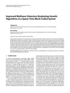
In Fig. 3, we illustrate the near-far resistance performance of the algorithms as a function of number of transmit antennas at an SNR of 15 dB. The transmit power on each of the transmit antennas is scaled such that����the total transmit ���!ë � power is the same in all the cases of & . We see that the SG algorithm, while being reasonably near-far resistant ��� � � for the cases of one and two transmit antennas ( & ), drastically loosesë its near-far resistance for four transmit � antennas ( ). For example, at a NFR of 20 dB, the & performance with four transmit antennas degrades to that of one transmit antenna, thus nullifying the diversity benefit of multiple transmit antennas. A similar performance behaviour can be observed for the MOE algorithm. This performance degradation at larger number of transmit antennas can be � � � attributed to the increase in the value of � ( � + ), the number of interfering bits per block. On the other hand, the RLS and the S-MMSE algorithms maintain their nearfar resistance very well even when the number of transmit antennas is increased. Hence, clearly, RLS and S-MMSE algorithms are preferred in multituser, multiple transmit antenna schemes from a near-far resistance point-of-view. However, being less complex than other adaptive detectors the SG algorithm may still be a preferred. In such a case, some transmit power control can be employed to compensate for the near-far resistance loss when more number of transmit antennas are used.
0
2
10 32 /
4
6
8 10 12 Near−far Ratio (in dB)
14
16
18
20
10 4 2
Fig. 3. BER performance of adaptive 8 23A receivers 8 as 2 aA function of NFR and g number of transmit antennas. , , SNR=15.6 dB.
K K In Fig. 2, we compare the convergence behaviour of the algorithms in a dynamic multiuser environment where users may dynamically enter and exit the system. A dynamic multiuser environment is simulated wherein the near-far ratio is increased from 10 to 18 dB (i.e., the power of the interfering user is increased by 8 dB, or, equivalently, a new interferer ë H{) H " with 8 dB of power enters the system) at the f & block, and the near-far ratio is reduced back to 10 dB (i.e., the power of the interferer comes down to the original value, or, equivalently, the interferer with 8 dB of power leaves H " block. From the left figure of the system) at the f &��{H8� Fig. 2, it is observed that the RLS algorithm is able to track such dynamic power imbalances in the channel at a faster speed (and also converge to a smaller MSE) compared to the SG algorithm. In the right figure of Fig. 2, we present a similar comparison between the MOE and the S-MMSE algorithm (no training data algorithms). It is observed that the S-MMSE is able to track the dynamic variations in the MAI much better (converge faster and to a smaller MSE) than the MOE algorithm.
We presented a comparative performance evaluation of adaptive multiuser detectors under near-far conditions in a space-time coded CDMA system. We showed that increasing in number of transmit antennas degraded the near-far resistance of the stochastic gradient (SG) and the minimum output energy (MOE) detectors significantly at high near-far ratios, to the extent that the diversity benefit of multiple transmit antennas is nullified. The recursive least squares (RLS) and the subspace based MMSE (S-MMSE) algorithms, on the other hand, were shown to maintain their near-far resistance without loosing much on the diversity gain, when the number of transmit antennas is increased. R EFERENCES [1] V. Tarokh, H. Jafarkhani, and A. R. Calderbank, “Space-time block codes from orthogonal designs,” IEEE Trans. Inform. Theory, vol. 45, no. 5, pp. 1456-1467, July 1999. [2] B. Hochwald, T. L. Marzetta, and C. B Papadias, “A transmitter diversity scheme for wideband CDMA systems based on space-time spreading,” IEEE JSAC, vol. 19, no. 1, pp. 48-60, January 2001. [3] S. Verdu, Multiuser Detection, Cambridge University Press, 1998. [4] X. Wang and H. V. Poor, “Space-time multiuser detection in multipath CDMA channels,” IEEE Trans. Sig. Proc., vol. 47, no. 9, Sept. 1999. [5] H. Huang and H. Viswanathan, “Multiple antennas and multiuser detection in high data rate CDMA systems,” Proc. IEEE VTC’2000. [6] X. Wang and H. V. Poor, “Blind multiuser detection: A subspace approach,” IEEE Trans. Inform. Theory, pp. 677-690, March 1998.