signed to detect and recover from link breakages, but are. 1This work was supported ..... effects of reading or writing data to hard disk drives. Consequently, the ...
Submitted to IEEE Milcom 2007
Performance of an Adaptive Routing Overlay under Dynamic Link Impairments Brian L. Mark, Shidong Zhang, George Mason University Rick McGeer, Jack Brassil Puneet Sharma, Praveen Yalagandula, HP Laboratories
Abstract—We propose an adaptive software routing overlay to improve the performance of TCP/IP-based internets over links with dynamic impairments. The routing overlay adaptively distributes traffic optimally over a set of alternative paths based on real-time link status information provided by a system of network sensors. The routing overlay also provides explicit rate feedback to rate-aware TCP clients, allowing them to achieve higher throughputs than legacy clients under static link loss and delay impairments. We present performance results from a collection of Emulab experiments on simple network topologies with dynamic link impairments. The results show that the adaptive routing overlay achieves significantly higher bulk file transfer throughput than legacy systems in the presence of link impairments. Sensor-based adaptive routing provides substantial gains in TCP throughput even for legacy TCP clients. When rate-aware TCP clients are used, the performance gain of the adaptive routing overlay with respect to legacy systems improves dramatically.1
I. I NTRODUCTION It is well-known that the performance of TCP/IP-based internets degrades severely in the presence of link impairments in the network. In particular, the throughput of TCP is drastically reduced under conditions of high link packet loss rate and large bandwidth-delay products. Various enhancements to legacy TCP have been proposed to improve its performance under static link impairments. When the link impairments are dynamic, the effectiveness of such enhancements may be limited. Besides the deficiencies of the legacy TCP transport protocol, the poor responsiveness of the legacy IP network layer can result in low throughput under dynamic link impairments. Tactical networks may consist of various wireless links, including satellite and mobile communications links, which may be characterized by link impairments that change over time. Legacy IP routing protocols are designed to detect and recover from link breakages, but are 1 This work was supported in part by DARPA Contract N66001-059-8904 (Internet Control Plane) and in part by NSF under Grant ACI133390.
not sensitive to dynamic changes in link loss or link delay. IP routing protocols typically determine the shortest path based on minimizing the number of hops in the path, but do not take into link loss or delay characteristics along the path. Re-routing traffic over alternative paths may provide improvements in TCP throughput, especially under dynamic link impairments. In this paper, we propose an adaptive routing overlay, which senses the underlying link delay and loss characteristics and reroutes traffic onto the best paths in terms of end-to-end throughput. The adaptive routing overlay is based on a software flow router called SAFIRE.2 SAFIRE is one component of the Control for High-throughput Adaptive Resilient Transport (CHART) system, which provides an enhanced network control plane (cf. [1]). We present empirical performance results for the proposed adaptive routing overlay on two sample network topologies. The experiments presented here were performed on the Emulab [2] network emulation testbed. Our experimental results show that the adaptive routing overlay can significantly improve TCP performance under dynamic link impairments. The proposed software routing overlay can also provide explicit rate feedback to rate-aware clients to improve TCP performance along a given network path with link impairments. In the TCP-ER protocol discussed in [1, 3], routers in the network provide explicit rate (ER) information on the available bandwidth along a given network path to rate-aware clients via an in-band signaling protocol [4]. Our results show that the combination of adaptive routing and explicit rate signaling can achieve dramatic performance gains with respect to legacy TCP/IP under dynamic impairments. The remainder of this paper is organized as follows. Section II describes the SAFIRE router. Section III describes the interaction between the adaptive routing overlay system and the network sensing infrastructure. Sec2
The name SAFIRE is derived from Software Adaptive FlowIntelligent RoutEr.
2
tion IV describes test tools and sample network topologies used to generate performance results. Section V first presents performance results comparing the performance of legacy TCP and explicit rate TCP under static impairments. Then performance results for the adaptive routing overlay under dynamic impairment schedules are presented for legacy TCP and TCP-ER. Finally, Section VI summarizes the main results and contributions of this work. II. S OFTWARE A DAPTIVE F LOW-I NTELLIGENT ROUTER The main features of SAFIRE are adaptive route control, flow routing, and in-band rate-based signaling. A. Adaptive route control The control plane of SAFIRE consists of a route control program, which implements an adaptive routing algorithm on the overlay network. The route control program is responsible for maintaining an IP routing table, which resides in the data plane of SAFIRE. For a certain predefined set of destination subnets, the route control program maintains a list of multiple paths and associated path metrics. The path metrics consists of the available bandwidth, packet loss rate, and delay over a given path in the overlay. The metrics are obtained from a network sensing infrastructure. Based on the path metrics, the route control program determines the best path (see Section III-B) and updates the routing table of SAFIRE accordingly. B. Flow routing SAFIRE implements flow routing in the data plane by means of a flow table, in addition to the conventional IP routing table. The flow table is indexed by a fixed length flow ID. The flow ID is computed as a hash of five fields extracted from the IP packet header: source IP address, destination IP address, source port number, destination port number, and priority. The flow ID is an index into a flow table, which is an array of entries. Each entry contains two fields: a next hop pointer and an activity counter. The next hop pointer points to the IP routing table entry corresponding to the longest prefix match associated with the flow’s destination IP address. A positive value of the activity counter indicates that the flow table entry is active, whereas a zero value indicates that the entry is inactive. Periodically, a flow maintenance process decrements positive-valued activity counters of all flow table entries, and maintains a count of the number of active flows associated with each outgoing interface.
When a packet arrives to SAFIRE, its associated flow ID is computed from the five aforementioned fields in the packet header. If the flow table entry corresponding to the computed flow ID is active, as indicated by the value of the activity counter, the packet is sent on the outgoing interface indicated by the next hop pointer. Also, the activity counter associated with the flow is incremented by one. If the entry corresponding to the computed flow ID is inactive, the entry is rendered active, by setting the activity counter to a predefined positive value. A full IP lookup on the IP destination address is then performed to find the appropriate routing table entry. The next hop pointer in the flow table entry is then set to point to this routing table entry. Finally, the packet is sent on the outgoing interface indicated by the next hop pointer.
C. In-band rate-based signaling SAFIRE implements available rate (AR) provisioning as described in the TIA 1039 in-band explicit rate signaling protocol [3, 4]. In this protocol, which we call TCPER (for TCP-Explicit Rate) in this paper, the sender inserts a so-called QoS (Quality-of-Service) structure into the TCP data portion of one out of every Nqos outgoing packets3 . The QoS structure contains, among other fields, an available rate (AR) field. SAFIRE extracts the QoS structure in an arriving packet, if any, and overwrites the AR field with the minimum of its current value and the fair share per flow available rate on the associated outgoing link. To compute the fair share rate at an outgoing interface, SAFIRE maintains an estimate of the number of active flows and the available bandwidth on the interface. When the destination receives a packet containing a QoS structure, it extracts the QoS structure, modifies the AR field to reflect the local available rate if necessary, and then inserts it into a packet traversing the reverse path to the sender. Thus, the sender learns of the bottleneck path rate in one round-trip time and does not rely on packet losses to infer the correct transmission rate. Consequently, TCP-ER avoids the slow-start problems and is much more resistant to link loss and delay impairments than legacy TCP (cf. [5]).
III. A DAPTIVE ROUTING AND N ETWORK S ENSING The main feature of the SAFIRE overlay studied in this paper is the interaction between network sensing and adaptive routing to shift traffic onto the best paths when the network is subjected to dynamic impairments. 3
Typically, Nqos = 128.
3
A. Network Sensing Infrastructure To perform adaptive, alternative routing on a SAFIRE routing overlay, a network sensing infrastructure called the CHART Sensing Infrastructure (CSI) is introduced to provide real-time path metric information. CSI is derived from the network sensing capabilities provided in the Scalable Sensing Service (S 3 ) discussed in [6]. In particular, the CSI service provides estimates of the capacity, latency, and packet loss rate over a given path in the network. We assume that CSI is instantiated at each SAFIRE node in the network. The route control program in each SAFIRE makes requests to CSI for the capacity, latency, and loss rate estimates associated with each of its attached overlay links to its neighboring SAFIRE nodes. To make the adaptive routing overlay scalable to larger sizes of networks, CSI should be integrated with a routing protocol that distributes the overlay link states to the SAFIRE nodes in an efficient matter. Such a routing service is a topic of ongoing work and is beyond the scope of the present paper. CSI determines the capacity of a given network path using the pathrate tool [7]. The capacity of a network path is equal to the capacity of the bottleneck link on the path. The pathrate tool estimates the path capacity by probing the path using a sequence of packet pairs and measures the resulting dispersion in packet arrival times. Note that the path capacity only changes if a link on the path goes down and the path is re-routed. Similar to the path capacity metric, the path latency typically changes only when a routing change occurs. CSI estimates the path latency by sending a sequence of ICMP probe packets and recording their round-trip latencies. The most dynamically changing path metric is the packet loss rate. The CSI estimates the packet loss rate over a path by periodically injecting a sequence of ICMP probes into the path. More precisely, once every Tloss seconds, the loss rate sensor injects a sequence of Nloss packets into a path with a spacing of xloss seconds. Let Lloss denote the number of ICMP packets in the sequence that are lost. Then the raw estimate of the one-way loss rate for a given loss interval of Tloss seconds is given by ε ≈ Lloss /Nloss . The raw loss rate estimates are then smoothed by averaging over two or more loss intervals. B. Throughput-based Route Selection The route control program in SAFIRE periodically updates the routing table to indicate, for each destination, the optimal path among multiple alternative paths based on path metrics provided by the CSI network sensing infrastructure. We define the optimal path as the one which
provides the highest throughput for a single TCP flow. We note that the TCP throughput along a given path depends on a number of parameters, including the path capacity, latency, and packet loss rate. In addition to these parameters, TCP throughput depends on the nature of any cross-traffic that traverses part or all of the given path. In this paper, we shall assume that there is no cross-traffic. Cross-traffic can be dealt with using a bandwidth probe mechanism, but a discussion of such a mechanism is beyond the scope of the present paper. For the purposes of route selection for legacy TCP traffic, we use a well-known simple approximation for TCP throughput (cf. [8, 9]): � � MSS √ , tleg ≈ min C, k (1) RTT ε where C is the path capacity, MSS is the maximum segment size, RTT is the round-trip time, ε is the packet loss rate, and k is a constant of proportionality. Empirical measurements discussed in [9] suggest that setting k = 1 provides an approximate upper bound to the throughput of legacy TCP. For our adaptive routing experiments, we simply set k = 1. The throughput formula (1) gives the approximate throughput achieved by legacy TCP along a path as a function of the path capacity, the loss rate, and the latency. Each SAFIRE node calls CSI to obtain real-time estimates of these path metrics for the outgoing overlay links, as discussed in Section III-A. The formula (1) provides a measure of the goodness of a particular path in terms of TCP throughput. The best path among a set of alternative paths is then defined as the one having the highest TCP throughput, as given by (1). If TCP-ER is used in the network instead of legacy TCP, a different throughput formula from (1) should be used. In our experiments, we have used the following approximate formula for TCP-ER throughput suggested by L. Roberts [5]: ter ≈
0.95C , (1 + αp)(1 + βRTT)
(2)
where α and β are constants. In our experiments, we have used the values α = 25 and β = 2.74 × 10⁻³ . Analogous to (1), formula (2) provides an approximate measure of the goodness of a path in terms of TCP-ER throughput. For TCP-ER flows, the optimal alternative path is the one having the highest TCP-ER throughput, as given by (2). A bandwidth ratio test is used to decide whether to switch from the current path to the current optimal path, as determined by the throughput formula. A routing change is initiated when the optimal path is more than a given
4
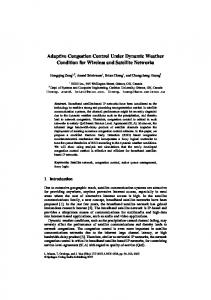
north bridge link impairments
sat1 link: 45 Mbps, 270 ms delay sat2 link: 3 Mbps, 150 ms delay
south bridge link impairments
Fig. 1. Domestic overlay topology on Emulab. Fig. 2. Forward overlay topology on Emulab.
percentage η better in terms of TCP throughput than the current path and if the previous routing change occurred at least Tch seconds earlier in time. The latter condition ensures that the current path remains valid for at least Tch seconds. This requirement is imposed to prevent the phenomenon of route-flapping, which can lead to degraded network performance. In our experiments, we set η = 0.5, i.e., the route is changed from the current path to the optimal path if the latter provides 50% better throughput, which is computed using (1) or (2), depending on whether the traffic is legacy TCP or TCP-ER. Though the throughput formula (1) can be inaccurate at high loss rates, the bandwidth ratio rule makes reasonable decisions under the dynamic impairments considered in this paper. A more accurate estimate of legacy TCP throughput could be obtained by using a more detailed approximation (cf. [10]) or by tabulating empirical measurements of TCP throughput. Similarly, a more accurate estimate of TCP-ER throughput could be obtained with a more detailed analysis, including empirical measurements. For the purpose of studying alternative routing under dynamic impairments, however, we have found the formulas (1) and (2) to be adequate. IV. I MPLEMENTATION AND T ESTING E NVIRONMENT The SAFIRE routing overlay was instantiated on the Emulab network emulation platform on nodes running Linux. A. Click Implementation of SAFIRE The data plane of SAFIRE was developed using the Click Modular Router platform [11]. Click provides a user-level software routing platform for the data plane of a conventional IP router. The functionality of Click can easily be extended by adding new modules to the Click package. We have added modules to the Click package to implement the basic flow routing functions: • Processing of TIA 1039 QoS headers;
Flow table maintenance; Available Rate (AR) computation. The control plane of SAFIRE interacts with the Click data plane using a socket-based interface. To perform adaptive routing, the control plane dynamically modifies the IP routing table and flow tables. • •
B. Emulab experiments Two network topologies are used in our experiments on Emulab [2]: the Domestic topology shown in Fig. 1 and the Forward topology shown in Fig. 2. These topologies are chosen to emulate network topologies created by DARPA [1, 12, 13] for testing network performance under dynamic link impairments. In the Domestic topology, four SAFIRE nodes are instantiated as nodes west0, north, south, and east0. All of the physical links in the Domestic topology have a capacity of 100 Mbps. The SAFIRE nodes perform rate processing on TCP-ER packets carrying the TIA 1039 QoS structure. Multiple client nodes (i.e., westc1 and westc2 in Fig. 1) are attached to a LAN (local area network), for which west0 serves as the gateway router to the rest of the network. For clients running either Legacy TCP or TCP-ER, the sender and receiver windows are set to 2.93 MBytes to ensure that the throughput is not limited by small sender or receiver windows. In general, the client nodes running TCP-ER respond to explicit rate feedback provided by the SAFIRE nodes in the network. Tunneling, by means of UDP tunnels, is used to connect the four SAFIRE nodes, although in the topology shown in Fig. 1 this is not strictly necessary. In general, however, tunneling can be used to override the behavior of underlying routing protocols such as OSPF. All of the SAFIRE nodes shown in Fig. 1 also run CSI. The route control program running on west0 obtains loss rate and latency information from CSI servers on four tunneled links: (west0, north), (north, east0), (west0, south),
5
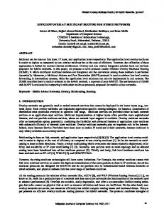
V. E XPERIMENTAL R ESULTS A. Static Impairments In the first set of experiments, we compare the performance of legacy TCP vs. TCP-ER on the SAFIRE overlay for a set of static link impairments on the domestic topology. Fig. 3 shows the throughput of legacy TCP and that of TCP-ER on the SAFIRE overlay for various combinations of link loss and delay. The link loss and delay impairments are applied symmetrically to the link (west0, north) on the north bridge and the link (west0, south) on the south bridge. For the legacy TCP results, all routers in the Domestic topology are Linux routers, i.e., SAFIRE is not instantiated on the routers. In the case of TCP-ER,
Kbps
TCP-ER vs. Legacy TCP through SAFIRE Overlay 100000 90000 80000 70000 60000 50000
TCP-ER Legacy TCP
40000 30000 20000 10000 50 /0.10 0 10 0/0.0 01 10 0/0.0 10 10 0/0.0 50 10 0/0.1 00
50 /0.05 0
50 /0.01 0
50 /0.00 1
20 /0.10 0
20 /0.05 0
20 /0.01 0
20 /0.00 1
10 /0.10 0
10 /0.05 0
10 /0.01 0
0/0 .100 10 /0.00 1
0/0 .050
0/0 .010
0/0 .001
0
delay (ms)/loss ratio
Fig. 3. Throughput comparison of TCP-ER on SAFIRE overlay vs. legacy TCP with static delay/loss impairments on Domestic topology. Loss Impairment Schedule
0.16 0.14 0.12 Loss Ratio
and (south, east0). Similarly, the route control program running on east0 obtains loss rate and latency information for the same four links. Hence, the loss rate and latency information for the north and south bridge paths is made available to the route control programs running on west0 and east0. The Forward topology shown in Fig. 2 consists of SAFIRE nodes west0, north, south, and east0, interconnected as in the Domestic topology, together with two additional satellite links, sat1 and sat2, and a fifth SAFIRE node top. The SAFIRE nodes perform rate processing by modifying outgoing TCP-ER packets that carry the QoS header to reflect the fair share of available rates on outgoing links. In the Forward topology, the links sat1 and sat2 present link capacity bottlenecks in the network. In Fig. 2 all links have a capacity of 100 Mbps, except for sat1, which has a capacity of 45 Mbps and sat2, which has a capacity of 3 Mbps. The latencies on the sat1 and sat2 links are set to 150 ms and 270 ms, respectively. In the Forward topology, west0 overwrites the AR (Available Rate) field of QoS packets (i.e., TCP-ER packets carrying the QoS structure) traversing the link (west0, top) with the value 0.9 × 45 Mbps to reflect the usable capacity of the sat1 link. Similarly, east0 overwrites the AR field of QoS packets on the link (east0, top) with the value 0.9×3 Mbps to reflect the usable capacity of the sat2 link. Likewise, top performs rate processing for packets flowing in the reverse direction to west0 and to east0. TCP throughput performance is measured using the iperf version 2.0.2 test tool as reported at a receiver. Iperf executes transfers between sender main memory and receiver main memory, and hence does not measure the effects of reading or writing data to hard disk drives. Consequently, the reported throughput numbers represent achievable network throughputs, and tend to be slightly higher than throughputs reported for bulk file transfers using applications such as ftp.
0.1 North Bridge South Bridge
0.08 0.06 0.04 0.02 0 1
2
3
4
5
Period
Fig. 4. Dynamic loss impairment schedule.
the SAFIRE overlay is instantiated with SAFIRE routers as discussed above. Each value reported in Fig. 3 is the average of three independent runs using iperf on Emulab. Fig. 3 clearly shows the superior performance of TCP-ER compared to legacy TCP in the presence of static link impairments. B. Dynamic Impairments In the next set of experiments, we impose a dynamic loss impairment schedule as shown in Fig. 4 for various delays applied symmetrically to the north and south bridges of the Domestic topology. As shown in Fig. 4, the impairment schedule consists of five periods. In period 1, the loss rate is 0.15 on the north bridge and 0.05 on the south bridge. The loss rate then becomes 0.05 on the north bridge and 0.15 on the south bridge during period 2. The rest of the impairment schedule can be inferred from Fig. 4. Fig. 5, shows the throughputs obtained with legacy TCP on the north and south bridges (with no SAFIRE overlay), and with TCP-ER under adaptive route control on the SAFIRE overlay. The throughputs achieved with legacy TCP on the two paths are roughly the same. In fact, un-
Legacy TCP vs. TCP-ER on Domestic Topology: T=120s
Legacy-TCP vs. TCP-ER on Domestic Topology: T=60s
18000
16000 legacy TCP: north bridge 14000
legacy TCP: north bridge
16000
legacy TCP: south bridge
legacy TCP: south bridge 14000
TCP-ER: SAFIRE overlay throughput (Kbps)
12000 throughput (Kbps)
6
10000 8000 6000
TCP-ER: SAFIRE Overlay
12000 10000 8000 6000
4000
4000
2000
2000 0
0 0
20
50
1
100
3
4
latency (ms)
latency (ms)
Fig. 5. Comparison of Legacy TCP vs. TCP-ER for Domestic topology with dynamic impairments: T = 60 s.
2
Fig. 6. Comparison of Legacy TCP vs. TCP-ER for Domestic topology with dynamic impairment schedule: T = 120 s. Legacy TCP and TCP-ER/SAFIRE, Forward Topology: T=60s 250
200 throughput (Kbps)
der OSPF, legacy TCP traffic traverses either the north or south bridge for the entire duration of the iperf session. Whether the north or south bridge is taken is effectively a random choice, since OSPF assigns the same cost to both paths, unless the OSPF link weights are purposely chosen to differentiate the two paths. We remark that a loss rate of 0.15 is not sufficient for OSPF to detect a link impairment that would cause rerouting to occur. On the other hand, the TCP-ER traffic carried on the SAFIRE overlay is switched dynamically onto the path of smaller loss rate by the route control programs executing on the SAFIRE nodes west0 and east0. As can be seen in Fig. 5, the combination of network sensing and adaptive routing provided by the SAFIRE overlay results in a substantial performance gain over legacy TCP with OSPF under the impairment schedule of Fig. 4. For these experiments, the CSI calculates link loss rates once every Tloss = 60 s. A more responsive loss rate sensor should improve the performance further under dynamic impairments. To test this hypothesis, we increased the impairment period to T = 120 s. The corresponding throughput results are shown in Fig. 6. One can observe superior throughput performance of the TCP-ER traffic compared to the case of T = 60 s. Fig. 7 compares the performance of legacy TCP on the north/south and top bridges on the Forward topology versus that of TCP-ER through the SAFIRE overlay. The north/south bridge refers to the two paths that cross the north and south bridges, respectively, and then traverse the low capacity sat2 link. Since the north and south bridge paths are identical in this case, we refer to them collectively as the north/south bridge. The top bridge refers to the path that traverses the high capacity sat1 link. Again, depending on the weights used for OSPF, legacy TCP would take either the north/south bridge or the top bridge.
150
100
50
0 north/south bridge
top bridge
SAFIRE
transport method
Fig. 7. Comparison of Legacy TCP vs. TCP-ER for Forward topology with dynamic impairments: T = 60 s.
The dynamic impairments applied to the Forward topology consist of packet loss impairments on the sat1 and sat2 links, which are associated with the top and north/south bridges, respectively. The impairment schedule for the Forward topology is the same as the one shown in Fig. 4 for the Domestic topology, with top bridge replacing north bridge and north/south bridge replacing south bridge in the figure. Fig. 7 shows that the performance of TCP-ER through the SAFIRE overlay is about 50% better than that of legacy TCP on either the north/south or top bridges. We note that while the SAFIRE overlay solution performs better than legacy TCP on either path, there is certainly room for improvement. If we increase the impairment interval to T = 120 s, the performance improvement reaches nearly 300%, as shown in Fig. 8. As in the Domestic dynamic impairment experiments, the 60 s response interval of the CSI loss rate sensor results in a performance degradation when the impairment interval is relatively small, i.e., T = 60. When T is increased to 120 s, the magnitude of the performance hit is substantially decreased.
7 Legacy TCP and TCP-ER/SAFIRE, Forward Topology: T=120s
ACKNOWLEDGMENTS
500 450
The authors thank Dr. Lawrence Roberts of Anagran for providing the TCP-ER driver and for useful discussions about its performance and implementation.
throughput (Kbps)
400 350 300 250 200
R EFERENCES
150 100 50 0 north/south bridge
top bridge
SAFIRE
transport method
Fig. 8. Comparison of Legacy TCP vs. TCP-ER for Forward topology with dynamic impairments, T = 120 s.
VI. C ONCLUSION
We have developed an adaptive software flow router (SAFIRE) overlay and evaluated its performance under dynamic network impairments empirically on the Emulab network testbed. The SAFIRE overlay is one component of the CHART system [1], which combines two routing solutions with a common network sensing infrastructure. SAFIRE performs adaptive alternative routing using real-time overlay link performance metrics obtained from the CHART Sensing Infrastructure [1, 6]. In addition, SAFIRE performs explicit rate signaling for available rate flows according to the TIA 1039 in-band signaling standard [4]. A rate-aware client, called TCP-ER, adjusts its transmission rate according to explicit rate information received from the SAFIRE nodes in the network. The TCPER driver avoids the slow-start problem of legacy TCP and is much more resistant to throughput degradation in the presence of static link loss and delay impairments. We studied the performance of the SAFIRE overlay on two simple network topologies subjected to dynamic impairments using both legacy TCP and TCP-ER. Our empirical results on Emulab show that the adaptive routing scheme can substantially improve the throughput performance of legacy TCP traffic under dynamic impairments. When TCP-ER is deployed on the SAFIRE overlay, the performance gain is even more dramatic. To maximize the performance gain, the frequency of networking sensing updates must be sufficiently high to allow the overlay to react quickly to the dynamics of the link impairment schedule. Important issues for further study are the tradeoff between sensing frequency and route adaptivity, and the integration of CSI with a routing protocol on the SAFIRE overlay to provide more timely overlay link state information in an efficient and scalable manner.
[1] A. Bavier et al., “Increasing TCP Throughput with an Enhanced Internet Control Plane,” in Proc. IEEE Military Communications Conference (Milcom ’06), (Washington DC), Oct. 2006. [2] B. White et al., “An Integrated Experimental Environment for Distributed Systems and Networks,” in OSDI02, (Boston, MA), pp. 255–270, USENIX Association, Dec. 2002. [3] L. G. Roberts, “Major Improvements in TCP Performance over Satellite and Radio,” in Proc. IEEE Military Communications Conference (Milcom ’06), (Washington DC), Oct. 2006. [4] L. G. Roberts, “QoS Signaling for IP QoS Support, version 2,” tech. rep., Telecommunication Industry Association (TIA), April 2007. [5] L. G. Roberts. Private communication, July 2006. [6] P. Yalagandula, P. Sharma, S. Banerjee, S.-J.Lee, and S. Basu, “S3: A scalable sensing service for monitoring large networked systems,” in Proc. Workshop on Internet Network Measurement 2006, (Pisa, Italy), Sept. 2006. [7] C. Dovrolis, P. Ramanathan, and D. Moore, “Packet-dispersion techniques and a capacity-estimation methodology,” IEEE/ACM Trans. on Networking, vol. 12, pp. 963 – 977, Dec. 2004. [8] S. Floyd, “Connections with Multiple Congested Gateways in Packet-Switched Networks, Part 1: One-way Traffic,” Computer Communication Review, vol. 21, pp. 263–297, Oct. 21991. [9] M. Mathis, J. Semke, J. Mahdavi, and T. Ott, “The Macroscopic Behavior of the TCP Congestion Avoidance Algorithm,” Computer Communication Review, vol. 27, July 1997. [10] J. Padhye, V. Firoiu, D. Towsley, and J. Kurose, “Modelling TCP throughput: A simple model and its empirical validation,” in Proc. SIGCOMM Symp. Communications Architectures and Protocols, pp. 304–314, Aug. 1998. [11] E. Kohler, R. Morris, B. Chen, J. Jannotti, and M. F. Kaashoek, “The Click modular router,” ACM Trans. on Computer Systems, vol. 19, pp. 263–297, Aug. 2000. [12] J. Meagher, “SAIC Design Document for Performance Lab Testbed,” tech. rep., SAIC, July 2006. [13] J. Meagher, “SAIC Test Report for Performance Lab Testbed,” tech. rep., SAIC, Aug. 2006.