2206
IEEE PHOTONICS TECHNOLOGY LETTERS, VOL. 17, NO. 10, OCTOBER 2005
Performance of Single-Mode Fiber Links Using Electronic Feed-Forward and Decision Feedback Equalizers Philip M. Watts, Vitaly Mikhailov, Seb Savory, Polina Bayvel, Madeleine Glick, Martin Lobel, Benny Christensen, Peter Kirkpatrick, Song Shang, and Robert I. Killey
Abstract—The performance limits of optically amplified links using electronic feed-forward equalizers and decision feedback equalizers are experimentally and numerically investigated. A 10-Gb/s transmission over 140 km of standard single-mode fiber with 22.7-dB optical signal-to-noise ratio sensitivity at 10 9 bit-error rate is demonstrated, allowing single-span operation with 4-dB margin. Index Terms—Adaptive signal processing, chromatic dispersion (CD) compensation, optical fiber communications. Fig. 1.
I. INTRODUCTION
A
S metropolitan networks using standard single-mode fiber (SSMF) are upgraded to 10 Gb/s, some form of chromatic dispersion (CD) compensation is required. CD is a static impairment, causing intersymbol interference (ISI), which leads to significant penalties for links of over 60-km SSMF at 10 Gb/s. The use of electronic dispersion compensation (EDC) to combat CD is attractive because it avoids the use of optical modules which are expensive, bulky, and have high optical loss. EDC can provide an adaptive and cost-effective solution suitable for integration with other receiver functions. The rapid development of digital and mixed signal integrated circuits is now allowing the implementation of circuits operating at 10 Gb/s with acceptable power consumption. We investigated the use of electronic feed-forward equalizers (FFEs) and decision feedback equalizers (DFEs) following the detector in a direct detection link. This technique offers low complexity and power consumption compared to other techniques such as maximum likelihood sequence estimation [1], [2]. Also, in comparison to electronic precompensation techniques [3], the requirement for feedback from the receiver to Manuscript received April 1, 2005; revised June 24, 2005. This work was supported in part by U.K. Engineering, in part by Physical Sciences Research Council, and in part by e-Photon ONe. P. Watts, V. Mikhailov, S. Savory, P. Bayvel, and R. I. Killey are with the Optical Networks Group, Department of Electronic and Elctrical Engineering, University College London, London WC1E 7JE, U.K. (e-mail:
[email protected];
[email protected];
[email protected];
[email protected];
[email protected]). M. Glick is with Intel Research Cambridge, Cambridge CB3 0FD, U.K. (e-mail:
[email protected]). M. Lobel and B. Christensen are with Intel Copenhagen ApS, Skovlunde DK-2740, Denmark (e-mail:
[email protected];
[email protected]). P. Kirkpatrick and S. Shang are with Optical Technology Office, Intel Corporation, Newark, CA 94560 USA (e-mail:
[email protected];
[email protected]). Digital Object Identifier 10.1109/LPT.2005.856326
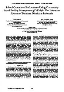
Five-tap FFE structure.
the transmitter is avoided. FFE and DFE have been shown to be effective for mitigation of multimode dispersion [4], polarization-mode dispersion [5], and restricted receiver bandwidth [6] as well as CD [7], [8]. However, no published study has presented a comprehensive analysis of FFE and DFE technology for combating CD. This letter presents 10-Gb/s experiments and simulations showing the performance of FFE and DFE in optically amplified links. Transmission distances up to 160 km are considered to demonstrate the limits of this technology. Of particular interest for metropolitan systems is the maximum achievable single span transmission distance (without any in-line amplification). This is found for various FFE and DFE configurations allowing the optimum configuration in terms of performance against complexity to be obtained. These results are experimentally verified by transmission experiments using an Intel integrated circuit. II. FFE AND DFE STRUCTURES The structure of a five-tap FFE is shown in Fig. 1. The FFE, also referred to as a tapped delay line or finite impulse response filter, has an output given by
where are the variable tap weights, is the number of FFE is the input at time , and is the time delay between taps, the taps [1]. All the FFEs used in this work had tap spacing of ps for 10 Gb/s) and the tap weights half the bit period ( to . In the simulations and exwere limited to the range periments, the values of were optimized to achieve the lowest bit-error rate (BER) using a maximum rate of descent method.
1041-1135/$20.00 © 2005 IEEE
WATTS et al.: PERFORMANCE OF SINGLE-MODE FIBER LINKS USING ELECTRONIC FFEs AND DFEs
2207
Fig. 2. Two-stage DFE structure. Fig. 4. Simulated OSNR sensitivity (10 BER) after 100–160-km SSMF transmission for various FFE and DFE configurations. Five-tap FFE and one-stage DFE is shown to be the optimum.
Fig. 3.
Experimental arrangement.
Because of the symmetrical nature of CD, the start point for opand all other timization was to set the central tap taps to zero. The structure of a two-stage DFE is shown in Fig. 2. It works by subtracting a proportion of previous decisions, controlled by the analog control voltages , from the incoming signal [1]. In this work, the control voltages were limited to the range 1 to 1. DFE sections can be cascaded, as shown in Fig. 2, to compensate for ISI from several previously detected bits. If using both the FFE followed by the DFE, in both simulations and experiments, the optimization was started with the FFE set to with all other taps zero. In this configuration, the FFE is used to compensate precursor ISI (caused by subsequent bits) while the DFE compensates postcursor ISI (caused by previous bits). III. SIMULATIONS OF FFE AND DFE PERFORMANCE Semianalytical simulations of the link shown in Fig. 3 were carried out to determine the optimum number of FFE taps and DFE sections. The transmitted signal was a 10-Gb/s nonreturnto-zero (NRZ) pseudorandom binary sequence (PRBS) of , with extinction ratio of 16 dB generated using a length realistic Mach–Zehnder modulator model. CD (16 ps/nm km) of the SSMF was the only source of distortion included in the simulation. The receiver bandwidth neglecting the effect of the FFE was 9 GHz. It was assumed that signal-spontaneous beat noise was the dominant noise source, approximated using signal-dependent Gaussian distributions [9]. This approximation is accurate for the low BER regime considered in this work. The amplitude and phase of the decision point were adjusted to obtain the lowest BER. The performance criterion used in all simulations and experiments was the optical signal-to-noise BER. ratio (OSNR) in a 0.1-nm bandwidth, required for Fig. 4 shows the effect of varying the number of FFE taps after transmission over 100–160 km. For the FFE alone, increasing the number of taps from 5 to 13 gave a 3-dB sensitivity improvement after 140 km. However, for the FFE and DFE combination,
Fig. 5. Simulated OSNR sensitivity for SSMF ranges up to 160 km (10 BER) for various FFE and DFE configurations and (inset) back–back eye diagrams in the uncompensated and five-tap FFE cases.
there was no significant advantage in using more than five FFE taps. Adding additional DFE sections did not improve the performance significantly at the transmission distances considered in this simulation. Hence, the five-tap FFE and one-stage DFE combination is optimum in terms of performance against complexity. Simulation results for back-to-back operation and transmission distances of up to 160-km SSMF are shown in Fig. 5 for various configurations. All FFEs enabled a back-to-back sensitivity improvement compared with the uncompensated case (1.2 dB for three-tap and 1.5 dB for five or more taps). This was achieved by setting two adjacent taps high ( 1). As shown in the eye diagrams in Fig. 5, the output signal was amplified and the eye remained open. To explain the sensitivity improvement, the autocorrelation functions of white Gaussian noise filtered by low-pass filters of 8–10 GHz are plotted in Fig. 6. It can be observed that at 50 ps (the FFE tap spacing), the correlation is low, implying that each tap is an independent noise source. Thus, when two adjacent taps are set high, the average signal is doubled, but the average noise level is only increased , thus increasing the output signal-to-noise ratio. Howby ever, as shown by the ISI on the compensated eye diagram in Fig. 5, the BER improvement comes at the expense of reduced timing or jitter margin. There was no back-to-back improvement when the DFE was used alone. The use of a nine-tap FFE reduced the required OSNR by 3.8 dB after transmission over 100-km SSMF, and by 6.9 dB after 120-km SSMF. The addition of a single DFE section was found to give considerable benefit at ranges above 100 km.
2208
IEEE PHOTONICS TECHNOLOGY LETTERS, VOL. 17, NO. 10, OCTOBER 2005
Fig. 6. Autocorrelation functions of low pass filtered white Gaussian noise.
The OSNR at the detector in a single-span (no in-line amplification) optically preamplified link depends on the transmission power and the noise figure of the receiver erbium-doped fiber amplifier (EDFA). The obtainable OSNR with 0-dBm launch power, fiber loss of 0.2 dB/km, and 5-dB EDFA noise figure is plotted in Fig. 5. On this basis, a nine-tap FFE allows a maximum single span length of 141-km SSMF, while five-tap FFE with a single stage DFE allows a span length of 156 km with BER. IV. TRANSMISSION EXPERIMENTS The experimental arrangement is shown in Fig. 3. The transmitter used a tuneable laser and a Mach–Zehnder modulator, . The resulting NRZ driven by a 10-Gb/s PRBS of length optical signal had an extinction ratio of over 10 dB. The fiber link consisted of up to 140 km of SSMF in one or two EDFA amplified spans. Two spans were required in order to measure the sensitivity with the FFE alone at 140 km. The maximum OSNR obtainable with 140 km in a single span in this experiment was 26.7 dB (measured in a 0.1-nm resolution bandwidth). The launch power into each span was maintained at 0 dBm to avoid distortion due to fiber nonlinearity. The effect of polarization-mode dispersion in the experiment was negligible. At the receiver, an EDFA, a variable optical attenuator, and coupler were used to control the OSNR at the detector. A bandpass optical filter, of bandwidth 1.6 nm, removed out of band amplified spontaneous emission (ASE) noise before the avalanche photodiode detector. A constant optical signal power of 18.5 dBm was maintained at the detector, ensuring that signal-ASE beat noise dominated over all other noise sources. The EDC integrated circuit contained a five-tap FFE, clock/data recovery (CDR), and a two-stage DFE. The circuit layout allowed the use of either the FFE alone (with CDR) or the FFE and DFE together. The taps were adjusted manually to find the optimum BER in each case. BER The measurements of required OSNR to achieve are plotted in Fig. 7, along with the simulated results. The experimental results generally agree well with the simulations. The difference between the simulation and experimental results for the combined FFE and DFE at 116 and 140 km, can in part be for simuexplained by the difference in PRBS length ( for experiments). Using a PRBS length lations, experimentally resulted in required OSNR values of 19.6 and 21.8 dB at ranges of 116 and 140 km, respectively, closer to the
Fig. 7. Experimental (markers) and simulated (lines) OSNR sensitivity at 10 BER for 0–160-km SSMF transmission distances.
simulated figures (19.1 dB at 116 km and 21.1 dB at 140 km). At shorter distances, the PRBS length had no significant effect. The FFE and DFE combination requires an OSNR of 22.7 dB PRBS length after 140-km SSMF, thus allowing a with 140-km single span with 4 dB of OSNR margin. V. CONCLUSION The transmission distance limits of 10-Gb/s optically amplified SSMF links using FFE and DFE are reported. Simulations predict that a five-tap FFE allows a maximum single span range of 138-km SSMF, while adding a single-stage DFE allows 156 km. Five-tap FFE and one-stage DFE has been shown to be the optimum configuration in terms of performance against complexity. The simulation results were experimentally verified by transmission experiments using an Intel five-tap FFE and two-stage DFE integrated circuit. Using FFE and DFE, a BER was measured after required OSNR of 22.7 dB at transmission over 140-km SSMF, allowing single-span operation with 4-dB margin. REFERENCES [1] S. Benedetto, E. Biglieri, and V. Castellani, Digital Transmission Theory. Englewood Cliffs, NJ: Prentice-Hall, 1987, ch. 8. [2] A. Färbert et al., “Performance of a 10.7 Gb/s receiver with digital equaliser using maximum likelihood sequence estimation,” in Proc. Eur. Conf. Optical Communications (ECOC 2004), Stockholm, Sweden, Paper Th4.1.5. [3] M. M. El Said, J. Sitch, and M. I. Elmasry, “An electrically pre-equalized 10 Gb/s duobinary transmission system,” J. Lightw. Technol., vol. 23, no. 1, pp. 388–400, Jan. 2005. [4] X. Zhao and F. S. Choa, “Demonstration of 10-Gb/s transmissions over a 1.5-km-long multimode fiber using equalization techniques,” IEEE Photon. Technol. Lett., vol. 14, no. 8, pp. 1187–1189, Aug. 2002. [5] H. Bülow, W. Baumert, F. Buchali, and W. Kuebart, “Adaptation of an electronic PMD mitigator by maximization of the eye opening,” in Proc. Eur. Conf. Optical Communications (ECOC 2000), Munich, Germany, Paper P.3.10. [6] G. S. Kanter, A. K. Samal, O. Coskun, and A. Gandhi, “Electronic equalization for enabling communications at OC192 rates using OC48 components,” Opt. Express, vol. 11, pp. 2019–2029, 2003. [7] F. Buchali, H. Bulow, W. Baumert, R. Ballentin, and T. Wehren, “Reduction of the chromatic dispersion penalty at 10 Gb/s by integrated electronic equalisers,” in Proc. Optical Fiber Communications (OFC 2000), Baltimore, MD, Paper ThS1-1. [8] S. Otte and W. Rosenkranz, “A decision feedback equalizer for dispersion compensation in high speed optical transmission systems,” in Proc. Int. Conf. Transparent Optical Networks (ICTON’99), Warsaw, Poland, Paper We.B.2. [9] G. P. Agrawal, Fiber-Optic Communication Systems, 3rd ed. New York: Wiley, 2002.