Performance of the Xenon Feed System on Deep Space One
Gani B. h a p a t h i t and Carl S. EngelbrechtS Abstract
Propulsion for the Deep Space One(DSl) spacecraft is provided by a xenon ion engine. Xenon is stored in a supercritical state and is delivered as a low pressure gas thruster and two cathodes (called the main cathode and neutralizer)
to the
by a Xenon Feed
System (XFS). This mission requires tight constraints on thruster performance, which in turn requires separate and very accurate throttlingof the thruster and cathode flows; the DS1 spacecraft is the first of its type to utilize a xenon ion engine that can be throttled. Flow is regulated separately to the thruster and cathodes to an accuracy of k 3% using three calibrated Flow Control Devices (FCDs) which are each fed by a dedicated plenum tank.Bang-bangregulatorsareused
to controlthesetpressuresintheplena.The
resulting XFS control algorithms are quite complex. The XFS is controlled by a Digital Control Interface Unit( D o and the control algorithm for achieving steadystate xenon flow is presented. The worst case error in flow is shown to be less than +/-3% accounting for random and systematic errors. At the time of writing, the individual components are
of the XFS is as expected. in excellent health and the performance Introduction
Deep Space One, launched on October24th 1998 by a Delta 11launch vehicle, is the first (IPS) used for primary propulsion.Its spacecraft with a throttleable ion propulsion system
primary mission is to validate 12 new technologies of which the IPS is the key one. As Senior EngineeringS W , Jet Propulsion Laboratory, M / S 125-109,4800 Oak Grove Dr., Pasadena, CA 91109. E-mail: gani.b.mmamthi@,id.nasa.~ov. AIAA Member Project Engineer, PRIMEX AerospaceCorp., P.O. Box 97009,11441 Willows Rd. NE, Redmond, WA 98073. E-mail:
[email protected] Member
part of the primary mission, it flew mission is planned for
by an asteroid, 1992
KD in July ’99. An extended
an additional fly-by to comet Borrelly in Sept. ’01 (a plan for
another flyby to comet Wilson-Harrington in Jan. ’01 has been dropped). The propulsion system, developed under the Solar Electric Propulsion Technology Application Readiness (NSTAR) program14, includes a 30 cm gridded ion engine which is capable of providing a maximum thrust of 92 mN at an Isp of approximately 3 100 sec. The working fluid for this engine is xenon, stored in a supercritical stateto optimize tank mass and volume, and delivered at low pressures to the engine by the Xenon Feed System (XFS). The purpose of this paper is to describe the XFS and detail the performance of the
XFS following
launch and compare it with what was predicted.
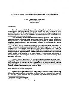
XFS Description and Requirements The XFS schematic is shown below in Fig. 1. Tank
T1 was initially loaded with
81.5 kg of xenon; the tank has a volume of 49.62 liters. The initial load pressure“C at 21 was 7 . 5 7 7 ~ 1 Pa 0 ~(1099 psia). “Bang-bang” regulators R1 and R2 (each made up of
an
assembly oftwo series solenoid valves) are usedto regulate pressure in the plenum tanks A1 and
A2.
The 3.7-liter plenum tanks are required
to smooth out the pressure spikes
associated with the “bang-bang’’ regulators. Latch valves LV3, and LV4 provide a third seal between the high-pressure propellant tank and the low-pressure plena,to assure the prevention of over-pressurization of the plena during ground handling. LV1 and
LV2
provide on-off control of flowto the engine, and LV5 provides a means of operating the
XFS in case of failure in one of the flow branches. (No discussion of off-nominal XFS operation is included here, see Ref 6 for details.) The flow control devices (FCDs) J1, J2, and 53 are used to regulate the flow to the engine, and flex lines FL1, FL2 and FL3 are
required to allow engine gimballing. The flow control devices are porous sintered metal plugs, and the flow through such a porous plug is a knction of pressure and temperature. More details on the flow characteristics for such a device are presented in a later section. A multi-dimensional trade study was performed to determine optimized plenum characteristics.“Bang-bang”regulatormanufacturingtolerancesandcyclelife,range safety considerations, pressure and temperature sensor accuracy, and other variables were considered. The resulting system has 0.5 a X lo4 liter inter-solenoid volume and 3.7 liter plenum tanks with an operating pressure rangeof 2 . 7 6 ~ 1 0-~6 . 8 3 ~ 1 0Pa~ (40 - 99 psia) forthemainplenumand
2 . 7 6 ~ 1 0-~ 3 . 4 5 ~ 1 0Pa ~ (40 - 50 psia)forthecathodel
neutralizer plenum. Eachplenumtankisinstrumentedwithasetofthreetemperature-corrected (hardware and software) pressure transducers (maximum range= 1 . 0 3 ~ 1 Pa 0 ~ (150 psia); accuracy = 0.1%FS). The transducers are polled and the averageis used for the control algorithm (discussed later). In the event one transducer fiom a set
drifts significantly
is used. fiom the average, its telemetry is discarded and the average of thetwo other The FCDs were procured based on attainable flow accuracy and procurement turn-around time considerations. Turn-around time very is important since the procurementprocessinvolvesfine-tuningtheflowratesbasedontests,whichisan interative process. The FCDs were flight qualified JPL. at A comprehensive test planwas developed for procuring and calibrating the FCDs for the required flow accuracies. For the sake of brevity, only the error analysis is presented in a later section. Bushway, 111, E. et
aL5
documentmoredetailsonthe
XFS componentsandtheXenonComponent
XFS components are assembled. Assembly (XCA) plate on which the
The key XFS requirements, which relateto this paper, are shown in Table 1; full a set of requirements is documented in the NSTAR document ND-3306. Table 1 Selected requirementsfor XFS
Requirement 81.5 kg To within &3% of actual flow Main inlet: 0.6- 2.4 Cathode: 0.25- 0.37 Neutralizer: 0.24- 0.36 20 Range: - 50 Max. rate of change:1 "C/10 min
Total Xe load (kg) Flow accuracy Flow range (16 throttle levels); (mdsec) Temperature ('C)
The XFS is capable of providing any desired flow; however, the Digitial Control Interface Unit ( D O is programmedto provide 16 discrete throttle levels. The engine is designed to optimizethrustlevelbasedonavailablesolarpower.Thus,whenthe spacecraft is closeto the sun, it can throttle at a higher level than when isit further away. DS1currentlycanuseonly12oftheavailable16levelsdue
to availablepower
constraints.Figure2depictsthemissionthrottlelevelsanddistancefromsunasa fbnction of time after launch. In the next section, the control features
of the DCIU are
presented. Control of the XFS
NSTARthrusterand
XFS operationsarecontrolled
Interface Unit (DCIU). It is a -2kg,
by theDigitalControl
30x15~15cm box utilizing less than 12
W. It is
partitioned into 3 VME boards; a processor board, a data acquisition board and a valve driver board. The DCIU controls the XFS using the control algorithm shown in Fig. 3. Note that this control algorithm allows control during steady-state and throttling, and also has logic to handle fault situations such as leakage
or failure of the XFS latch andor
solenoid valves. The fault protection and its responses are beyond the scope of this paper. The DCIU polls all of the X F S temperature and pressure transducers every second and all telemetry values are updated for control and communication purposes. The DCIU control algorithm compares the required and measured pressures (both corrected for temperature) and activatesthesolenoids measuredpressurevaluesareless
to pressurizetheplenaifthe
than therequiredvalues.Duringsteadystate
operations, the plena are in a continuous state of blowdown, and periodic replenishment via regulator activation is essential to maintain the flow rates. During throttle up, the latch valves LV1 and LV2 can be either closed or open depending on if the throttling is done prior to starting the engine or while the engine is thrusting
- both throttle modes are
allowed by the DCIU. During throttle down, as the required pressure is less measured pressure, no action
than the
is taken by the DCIU until the pressures match. At this
point, the DCIU continues with the normal steady state control scheme. Byreferring to Fig. 3, thesteadystateDCIUcontrolsequencewouldbeas follows: 1) Ground command determines the throttle level for the spacecraft. 2) Based on the throttle level, a throttle look-up table
in the DCIU is used to set the
required nominal plenum tank pressures. 3) The nominal required pressures are then adjusted for FCD temperatures.An increase
in FCD temperature has to be compensated by an increase in required pressure and visa versa to maintain a constant flow rate. These adjustments are based on 4-point linear interpolations of pressure correction values in look-up tables; there are
two
such 16x16 look-up tables in the DCIU, one for each flow branch.A voting scheme is
used to determine the averageFCD temperature for the correction, wherethe outlying temperaturevalue is discardedand the average of the best two are chosen.The adjusted required pressure values are called PAreq’d. A voting scheme similar to that in 3) is used to determine the temperatures of the
pressure transducers. Each of the pressure transducer values
is then corrected for
temperature using a linear interpolation schemeas in 3). The corrected pressures on eachbranch
are thenaveragedusingavotingscheme.Theaveragedmeasured
pressure valuesare called P&. Two fault conditionsare then checkedfor: a) over-pressurization, whenPA, is greater than PA req’d by a pre-defined limit, and b) under-pressurization, when PA, is less than PA req’d by a pre-defined limit. The fault condition limits are not the same.
If no fault conditions aremet and if the measured pressuresare less than the required ones, thenthe solenoids are activated to pressurize the plenum tanks. Pressurization of a plenum tankis achieved by sequential activationof the pair of solenoid valve inthe regulator as mentioned before. High-pressure xenon trapped within theinter-solenoidvolumefollowingan
opedclose cycle of the upstreamsolenoid is
injected into the plenum tank when the downstream solenoid is cycled
openklose. The
required open times of the upstream and downstream solenoids are a hnction of many parameters such as supply xenon pressure and temperature, solenoid temperature, and plenum tank pressure and temperature. It is important to optimize the solenoid cycle times, as mission pressurization times can be impacted particularly later in the mission when many regulator cycles are required to pressurize the plenum tanks due to lower xenon pressure inthe supply tank. Optimal open times are shown in Fig.4.
In Fig. 4, the plenum pressure is assumedto be 2 . 8 6 ~ 1 0Pa~ (41.5 psia), which is representative of the lowest pressures to be seen in the plenum tanks. A worst case y
(q&)
= 1.7 wasassumedforallthecalculations.
Also, uniform temperatures for all
components were assumed. Clearly, the optimal required open times passes through a engineering modelof the XFS peak around the critical pressure of xenon. Testing an with verified these trends and experimental values were close to model predictions. In order to ascertain that the XFS would satisfl the requirements imposed on it,an error analysis was conducted. The results are presented in the next section. Feed System Flow Uncertainty The flow uncertainty of the
XFS is made up of systematic and random error
components. The systematic error would constitute items such as pressure transducer driR and “sawtooth” error dueto the pressure profile within the plena caused by the bang-bang regulatoroperationalcharacteristics.Randomerrorsaredue
to uncertaintiesinthe
transducers, calibration, modeling, etc. The systematic errors are typically additive and the random errors are root mean squared together. Figure5 depicts the contributions due to random and systematic errors. The FCD characterization error is discussed first since this is the most involved. JPL’s FCD test stand utilizes mass flow meters, which are calibrated prior to each FCD
characterization.Thecalibrationsystem,which
is aprimarystandardtraceable
to
1 to 50,000 National Institute of Standards and Technology (NIST), measures flow in the
sccm (standard centimeter cubed per minute) range with an accuracy of
0.2% of flow
overtheentirerange.Thecalibrationprocedureinvolvesautomaticallyrecording voltages indicated by the mass flowmeter, as well as the temperatures and test pressures.
The flowmeter is calibrated over a range of flow rates and pressures representative of flight conditions. For all the tests, mass flowmeters were utilized; however different units were used to measuremainandcathodeflows.Theuncertaintiesassociatedwiththe different elements in the calibration process are: Calibration system: uncertainty: Voltage Calibration curve Temperature correction
fit error:
f
0.2% flowof
f
0.1%
f
0.26%
*O. 15%
The resulting flow calibration uncertainty,
Udib, is equal
to
f
0.37% (the root
mean square of the above-listed components). With calibrated a mass flowmeter, the FCDs were characterized with temperatures ranging from20 to 50 "C and upstream pressures ranging from2 . 4 1 ~ 1 Pa 0~ 0 ~(35 to 99 psia) for main and 2 . 4 1 ~ 1 Pa 0 ~ to 5 . 1 7 ~ 1 Pa 0 ~(35 to 75 psia) for to 6 . 8 3 ~ 1 Pa
cathode FCDs. The downstream pressure was maintained below a fewtorr in all cases. The flow characteristic of a porous plug such as the one used can be modeled as:
In Eq. 1 P I and p2 are upstream and downstream pressures respectively, G is the superficial mass velocity,gc is a dimensionless constant,A 4 is the molecular weight,R is the gas constant, T is absolute temperature, o and p are constants representative of the porous plug and p is the viscosity of the gas. However, this model was not adequate as the errorin fit was almostf 2%.An alternate non-phenomenological modelwas therefore developed with a curve fit error less thanf 0.8% over the entire range of pressures and temperatures. The modelwas of the form
Flow(press, temp)= a0 + al*press +a2*press2+ a3*press3 + a.+*temp+ as*press*temp + %*temp2+ a7*press2*temp2+ %*temp3
(2)
This equationalso has the advantage of being explicit in flow with the caveat that the downstream pressure is below 5 . 3 3 ~ 1 Pa 0 ~ (40 torr). When the uncertainties in test stand pressure and temp sensors are included, the model uncertainty is given by
AT
The terms inEq. 3 are non-dimensional fractional errors. Thus,otemp= -,
T
point to benotedin
Eq. 3 is that anyuncertaintyin
the pressurewillresultin
etc. A
an
approximately twofold increasein flow uncertainty, due to the approximately parabolic
of interest. nature of the flow-pressure curve in the regime The uncertainties intest stand pressure and temperature are f 689 Pa (* 0.1 psi) and f 0.5 "C respectively. Thus,for a worst case pressureof 2.76~10'Pa (40 psia) and 20
-
"C (293 K), the model uncertainty is f 1.2% In flight, the flow uncertainty is a fbnction of the above model uncertainty off 1.2% andplenumpressureand
2 . 0 7 ~ 1 0Pa~ (f 0.3 psi) and
f
FCD temperaturesensoruncertaintieswhichare
f
1 "C respectively; the corresponding worst case rms flow
uncertainty dueto random errors is
-* 1.9%
The sawtooth error component is additive to the random error and when averaged over many regulator cycles,the maximum sawtooth error can beas high as f 1% of flow. Thus, the total worst case uncertainty in flow is f 2.9%. The actual error will be less and is shown in Fig.6 as hnction of mission profile.
From Fig. 6, it can be seen thatas the mission progresses, the systematic error due to sawtooth decreases, as one would expect, due
to lower pressure slugs being used to
pressurize the plena. The random errorcan be seen to be a hnction of the throttle level, with lower pressures contributing to larger uncertainties in flow (see Fig. 2 for throttle levels). However, the maximum error
is less than 1.9% as mentioned earlier. Regions
where the errors are zero correspond to times where there is no thrusting and hence no flow.
In this error analysis itis assumed that the pressure transducer drift is zero, which maybevalidonlyfortheearlystagesofthemission;however,thesawtootherror decreases as xenonisconsumedandwillpartlycompensate.The unknown since there is no absolute measurement against which
true errorwillbe to determine pressure
transducer drift in flight.
XFS Post-Launch History The DS1 spacecraft was launched on October 24, 1998. Two days after launch the DCIU was turned on for the first time. Post-launch telemetry indicated that all
XFS
valves were in the closed state as expected and theXFS pressures and temperatures were within expected ranges. Four days after DCIU turn-on, on October
30, the first XFS
activity, FCD calibration, was started.In order to verify that the FCD calibrations did not shift as a result of launch, a plenum blowdown test was performed. In this mode, only latch valves LV1 and LV2 were opened to initiate xenon flow through the FCDs. The plenum pressures and temperatures were monitored over an eight-hour period and the pressure profiles were compared with expected values. Prior to the start of the test, the thruster was turned 30' off-sun(seeFig.
7 foraxes,thruster,
XFS plateand DCIU
locationsonthespacecraft).Theturn
to sunwasdone
to heatupthelinesinthe
spacecraft to help outgas any adsorbed water in the lines following launch. (Cathode life is significantly affectedby exposure to contaminants such as water and oxygen.)
in “diode”
On November 9, 1998, the thruster was turned on for the first time
of the gas occurs; however, the mode. In this mode, xenon flow is initiated and ionization ionized gas is not accelerated through the grids and hence no effective thrust results. The engine was runin this mode to outgas any remaining water in the thruster area. On November10,theengine
was turnedon to start acceptancetest #l. Thistestwas
designed to test all of the IPS subsystem performance parameters at 6 different throttle levels. However, after running nominally for 4.5 minutes, the engine shut itself off and couldn’t be turned back on despite thermal cycling and multiple restart commands. The DCIU was then turnedoff on November 1l* and was turned back on November24* to conduct additional thruster diagnostics. When the engine was commanded started up and since then has continued
to perform flawlessly. On November 30* the
rescheduledacceptancetest#1wasconductedandasignificantamount gathered to determinetheperformance
to turn on, it
of data was
of the IPS. Theresultsarepresented
in the
following sections below. XFS Component Status Latch VaZves:LV1 through LV4 have been cycled less than 100 times at the time
of preparing this document (May 99). They have been qualified for over 12,000 cycles. of a fault. The LV5 has not been cycled in flight- this valve will only be used in the case pre-launch measured internal leakage rate for all latch valves were at least 2 orders of magnitude less than the required 1 X 10” standard cm3 per sec (sccs). For post-launch, the pressures in the plenum tanks were followed for a periodof two weeks where there
was no thruster activity (1 1/10/98 to 11/24/98). Subsequent telemetry also indicated no leakage. Duringthis time there wasno discernable change inthe pressures leadingto the conclusion that LV1, LV2 and LV5 were not leaking. Conclusions on integrity of LV3 and LV4 was possible only by inference, but could not be provendue to the presence of solenoid valves SV1-SV4. is 2.07~1 O7 Pa (3000 psia) Pressure Transducers:The supply pressure transducer full scale with a rated accuracyoff 1.0% FS ( 2 . 0 7 ~ 1 0Pa; ~ 30 psi) without a calibration lookup table. However, with the loaded calibration data in the DCIU, the accuracy is f 6895 Pa (fl psi). Any drift can be detectedby comparing calculated xenon consumption by integration of flow with expected pressure at a given temperature. There are six 1 . 0 3 ~ 1 0 Pa~ (150 psia) low pressure transducers for the plena with three on each plenum with a rated accuracyo f f 0.1% FS with calibration lookup table. Component acceptancetests indicated that PA5 indicated a lower pressure thanthe other two cathode transducersby approximately 1 . 3 8 ~ 1 Pa 0 ~ (0.2 psi). XFS fbnctional testing indicated that in addition to PA5, PA1 on the main plenum also indicated a slightly low pressure. As a result, the XFS is flowing a bit “rich,” withan expected impactof 0.25 kg extra propellant use in the mission. The current thought is
to change the calibration on
these pressure transducers at a later time in flight to recti@ the problem. Regulators: The regulators RG1 and RG2 have been cycled 15,200 and
5,500
times respectivelyto date and are fbnctioning nominally.No internal leak is discernible. A conservative 4 second open time was chosen for the DS1 initial setting. This will be reduced as the mission proceeds. The duty cycle of the regulator is a variable that can be modified by changing the delay time between solenoid activation. Currently, the DSl is
operated at a 25% duty cycle (total regulator time
= 2 solenoids x 4 sec open time per
solenoid / 25% duty cycle= 32 sec) to minimize thermal impacts.
Temperature sensors:There are a total of 13 temperature sensors in theXFS. Supply tank- 1 (* 1.7 "C) Regulators - 2 (k 0.4 "C) Plenum tank (only main plenum tank instrumented) - 1 (* 1.7 "C) FCDs - 3 (* 0.4 "C) Pressure transducers- 6 (* 5 "C). TheFCDandregulatortemperaturesensorsare
500 SZ platinumResistance
Thermometer Devices (RTDs) and are the most important ones. The temperature sensors within the pressure transducers are
100 SZ platinum RTDs and
are not critical, as the
pressure transducers are internally temperature compensated with software-based
-
corrections needed only for large changes in temperature (A 15-20 "C). All of the temperature sensors with the exception of the supply tank temperature sensor (telemetry channel V-4054) are fbnctioning nominally.V-4054 was noted to have 25 - 28 OC (due to heater cycling) to 28 - 31 OC. started drifting from the expected range
Fortunately, IPS operations are not impactedin any way, and this channel is not used for xenon mass calculations either, as better means exist (discussed below). XFS Performance
Analytical models have been developed for different purposes during the design,
of the XFS. assembly, test and mission operation phases
Since the storage and utilization of supercritical xenon was involved, it is important to understandthethermodynamics
of xenonand
its impact on flightoperations.The
8. behavior of xenon is best understood with the help of Fig.
For a loading of 81.5 kg, the tank pressure will be8 . 4 1 ~ 1 0Pa~ (1220 psia) at 25
"C (between 20 and 30 "C). At this pressure and temperature, xenon is supercritical.But as the xenon in the tank approaches 60 kg, it can be seenthat the density/pressure profile becomes very steep, particularlyfor isotherms close to 16.7 "C, as the xenon is close to its critical state. Very slight changes in temperature cause large shifts in density/pressure.
Also, smalluncertaintiesinpressuretransducerreadings
can lead to largemass
estimation errors. It is important to avoid the 2-phase boundary for many reasons and hence the previously stated requirementfor the lower flight temperature bound of 20 "C. The equationof state for xenon canbe represented in many different ways such as the virial equationof state, van der Waals, etc.' However, these equations were foundto be inadequate for the accuracies required and theyare implicit when solving for specific volume (or density). This places a severe constraint for many calculations where density is calculated repetitively as it impacts both computational
time andaccuracy due to
propagation of small errors. The approach used
for all XFS analysis was to use the NIST thermophysical
properties software which utilizes a 32-term modified Bennedict-Webb-Rubin (MBWR) equationofstate'.Typicaluncertaintiesinthecalculatedstandardreferencedata
are
about 0.1-0.3% in density, 0.5-2% in enthalpy, 2-5% in heat capacities, 2% in viscosity, and 4-6% in thermal conductivity over a broad range generated using the NIST software.
of state variables. Figure 8 was
The following performance models were developed forXFS. the 1) FCDCalibration 2) Optimal regulator open time
3) Temperature correction algorithm 4) Throttling up and down 5) Xenon consumption as fbnction of mission
In thissection,comparisonsbetweenexpectedandactualflightdatawillbe presented where applicable. For example, no flight data are availableto validate optimal regulator open time; however, verification has been done at the engineering model feed system level. The xenon consumption model has been validated for the missionso far.
FCD Calibration: Pre-launchcalibrationsoftheFCDswereperformedonMarch 1998. Both plena were pressurizedto
5,
- 5.17~10'Pa (75 psia) and latch valves LVl and
LV2 were opened to initiate flow. After 8 hours the latch valves were closed again. The
-
average temperature of the FCDs during this period was 21 OC. The DCIU was turned
off for some portions of the test as there were some dc-critical activities that demanded it.Post-launchFCDcalibrationswereperformedonOct.30-31,1998.Theinitial
-
pressures in both tanks were 6.83~10'Pa (99 psia) and total period of flowwas for 22 hours. There were significant variations in temperatures(28 - 36 OC) in the FCDs dueto theturn
to thesunmentionedearlier.Comparisonsbetweenpre-andpost-flight
calibrations are presentedin Figs. 9and 10 inthe common pressure ranges.
Theabovecomparisonsshowsomedeviationbetweenactualpre-andpost-launch pressure profiles due to different temperatures; however, the model matches the postlaunch data very well. Temperature Correction Algorithm:As mentioned in the section for control of XFS, the
DCIU is loaded with two 16x16 temperature correction tablesfor the main and cathode plena to set the required throttle pressures which account for varying FCD temperatures.
E thetemperaturewassteady plenumpressurewouldbe However,since
at 21.1 OC (baselinetemperature),therequiredmain 5 . 2 4 4 ~ 1 0Pa ~ (76.06 psia) for a flowrate of
the temperaturefluctuatesbetween
18.51 sccm.
27.5 and 28.5 OC, therequired
~ psia) as seen in pressure fluctuates between 5 . 3 1 ~ 1 0Pa~ (77.0 psia) and 5 . 4 3 ~ 1 0(78.7
Fig. 11. Throttling Up: The model for predicting the time required for throttling up is based on knowledge of supplytemperature
andpressure,regulatortemperature,andplenum
pressure and temperature. With latch valves LV1 and LV2 closed, the model prediction has been to within a few percent of actual flight data; however, when
the throttling is
done withthe engine thrusting, the model prediction is not better than15%. For example, the predicted number of cycles needed to throttle up fiom throttle level 6 to 9 when thrusting was 25, while the actual number was 30. Thus, the model prediction is slightly off under thrusting conditions, but this has no impacton flow performance. The reason for the discrepancy has not been established. Figure 12 shows an exampleof throttling up done in acceptance test #1. Throttling Down: When the spacecraft throttles downto a lower throttle level, the plena continue to bleed down until the desired pressure is reached. The regulation algorithm
then “kicks in” to maintain the pressures. An example of throttling down from throttle level 12 to 11 is shown in Fig. 13. The actual time for throttle down matches prediction to within a few percent. A couple of points to note from Figs. 13 and 14 are: 1) the throttle up timeis much faster than throttle down time - each throttle down event
is associated with a finite xenon loss, as the plenum tank pressure decreases
to its
target value, whichis not usefbl for thrusting. 2) the setpoint for triggering the plenum re-pressurization is set such that at no point is thecathodeormainflowlessthannominal.Thisisbecausecathodelifeis significantlyaffected by flowstarvation.There
is somelossassociatedwiththis
“sawtooth”pressureandflowspikes;howeverthelossoverthemissionisnot significant (discussed later). PollingAlgorithm: Thepollingalgorithmfortheplenumpressuretransducerswas
designed to account for possible drifts in the transducers. The current algorithm first averages all the 3 transducers in each branch. Then if any of the transducers’ value is different from the average byO S % , that transducer value is discarded and the average of the other two are used.In the current implementation, 6 . 3 4 ~ 1 0Pa~ (0.92 psi) was used as a cut-off. However, this tolerance will be narrowed in fbture to 3 . 4 5 ~ 1 0(0.5 ~ psi). The polling algorithm tries to do a good job in the face
of many possibilities.
However, it needs fbrther attention particularly on howto handle transducers which have an offset since launch. One way
as mentioned earlier would be
calibrationoftheerringtransducersincetheoffset
to simply change the
is constantatallpressures.The
polling algorithm is currently causing the xenon flow to be a bit richer than required, which will impact the xenon inventory by approximately 0.25 kg if left uncorrected. Mission Profde and Xenon consumption
The optimal trajectory for the flyby power and thrust and the mission
of the asteroid is based on available solar
is designed accordingly. The xenon consumption is a
2 showed the variation of distance hnction of throttle level and duration of bum. Figure
from sun and thrust levels. As the distance fiom the sun increases, the amount of power available to the solar panels decreases and hence lower thrust levels are available. With the knowledgeof mission thrust profile, it is possibleto estimate the amount of xenon consumed through the mission. The estimated xenon consumption profile
is
shown in Fig. 14. While integration of nominal mission flow rates is the only way
to
estimate hture xenonconsumption,thereareothertechniques
to estimatecurrent
available xenon in the supply tank. One way would be to count the number of solenoid cyclesandanotherwouldbe
to trackthesupplytankpressureandtemperatureand
estimate mass fioman equation of state. However, both approaches face problems related to the supercritical storage of xenon and are used only as backup techniques. Calculation of xenon density is required to calculate the xenon mass using the “solenoid count” and “equation of state estimate” approaches.
As the xenon pressure in the supply tank approaches the critical value, very small errors in pressure and/or temperature estimates lead to large errors in mass calculations; 0 ~(5 psi) and an error in temperatureof 1 OC around e.g., an error in pressure of 3 . 4 ~ 1 Pa the critical point could lead to an error of up to 18 kg in mass calculations! Predicted valuesof xenon consumption for the mission are based on nominal flow rates; however, actual xenon consumption values are obtained
by integration of flows
calculated from plenum pressures and FCD temperatures. As an example, 15 Fig.shows a close-up view of the integration for mass consumption over approximately
1.5 hours.
Please note that Fig. 14 was based on the latest mission profile, and starts from Day125 (Feb. 27, 1999); 6.6 kg xenon was consumed prior to this period. 1 sccm = 0.09838 mg/sec to
For conversion,onecanusetherelationship
determine the amount of xenon consumed. Thus, in Fig. 15,24.66 sccm-hr correspondsto 8.73 gm consumed in a 1.5 hour period. The sharp sawtooth profile on average increases
the nominal flow by 0.75%. The sawtooth error is a fbnction of many factors such as As the
amount of xenon in the supply tank, plenum tank pressure, and temperatures. mission proceeds, and as xenon is consumed, this error decreases.
Summary and Conclusions This paper has focused on performance related issues of the Xenon Feed System used on DS 1. The XFS design has been shown to be adequate to provide xenon over the full throttling range of the IPS. In addition, the required flow accuracy of+/-3% has been
achieved over the entire throttling range. The control algorithms coded into the DCIU
of throttling up and down
have been shown to berobustandcapable setpointsaccountingfortemperaturechanges.All
the componentsare
to the desired hnctioning
nominally with the exception of calibration offsetstwo in of the low-pressure transducers and drift in the high-pressure transducer. Future changes changingthefaultycalibrationonthe
to the XFS envisioned include
two low-pressuretransducers,changingthe
solenoid open times and regulator delay times
to account for decreasing xenon supply
pressure, and changing the setpoint for plenum pressurization such that on average the flow rateis nominal.
In conclusion,wearegratified
addition,themodelsdeveloped
to notethatthe
In
XFS isperformingwell,
to predicttheperformancehaveproven
to bevery
accurate and thishas been a source of satisfaction to the authors.
Acknowledgements The research described in this paper was carried out by the Jet Propulsion Laboratory, California Institute of Technology, under a contract with the National Aeronautics and Space Administration. We extend thanks to John F. Stocky the program manager
of NSTAR for his
mS would not have happened. support and to the XFS team members without whom the We also wish to thank our industrial partners at Moog, Inc., who helped us assemble the XenonComponentAssemblyandprovidedmany
of thecomponents.Non-Moog
components were the pressure transducers, produced by Taber, the FCDs, produced
by
Mott, the supply tank, produced by Lincoln Composites, the plenum tanks produced by SCI, and the RTDs, producedby Rosemount. References 1
J. S. Sovey, et al., “Development of an Ion Thruster and Power Processor for New
Millennium’s Deep Space
1 Mission,” AIM-97-2778, presented the at33rd
1997. AIAA/ASME/SAE/ASEE Joint Propulsion Conference, Seattle, WA, June
J. E. Polk, etal., “Validation of the NSTAR Ion Propulsion System on the Deep Space AIM-99-2274, presented at the 35th One Mission: Overview and Initial Results,” 1999. AIAA/ASME/SAE/ASEE Joint Propulsion Conference, Los Angeles, CA, June
3
M. G. Marcucci and J.E. Polk, “NSTAR Xenon Ion Thruster on DS : Ground 1 and
Flight Tests,” 1-18, presented at the 8th International Conference on Ion Sources, Kyoto, Japan, Sept. 6-10, 1999. 4
J. A. Christensen, etal., “The NSTAR Ion Propulsion Subsystem for DS1,” AIAA-99-
2972, presented at the 35th AIAA/ASME/SAE/ASEE Joint Propulsion Conference, Los Angeles, CA, June 1999. ’Bushway, 111, E.,Engelbrecht, C., Ganapathi,G.,“NSTARIonEngineXenonFeed System: Introductionto System Design and Development”, IEPC 97-044, August 1997. %ngelbrecht, C.S., “NSTARXenonFeedSystem
(XFS) TechnicalRequirements
Document (TRD)”, NSTAR Document# ND-330, January, 1997. ‘Reid, R.C., Prausnitz, J.M., Sherwood, T.K., “The Properties of Gases and Liquids”, McGraw-Hill Book Company, 3‘d ed. (1977). 8
Friend, D.G., “NIST Standard Reference Database 12: NIST Thermophysical Properties of Pure Fluids”, U.S. Department of Commerce, National Institute of Standards and Technology, Gaithersburg, MD, Sept. 1992.
I-1
PT1 P
NSTAR XFS SCHEMATIC vedoll0.4
:I;
LEGEND
@Vl
Svmbd
@
Comuonent Deseri~th
Pressure Transducer
Service Valve
TP1 TP2
Xenon Filter
TP3 Solenoid Valve
Latchvalve
$
Flex Line
Flow Control Device
Voltage Isolator
0
Fig. 1 NSTARMFS Schematic
Gani B. Ganapathi
Temperature Sensor
2 0 0 4 0 0 6 0 0 8 0 0 1 o o o Time after launch (day)
Fig. 2 Throttle Level and distancefrom sun as function of time after launch
Gani B. Ganapathi
CORRECT SET PLENUM PRESSURE FOR FCD
Fig. 3 XFS Control Algorithm Flowchart
Gani B. Ganapathi
Solenoid Valve Open Times
0
200
400
600
800
lo00 14001200
Upstream Pressure (psia)
Fig. 4 Optimal solenoid open timesas function of supply pressure
Gani B. Ganapathi
Pi
d
-7"
m.
A FLOW DUE TO SYSTEMATIC
ERRORSAWTOOTH DUE B Td +o B * N G m u m x ) 3
3 LL
MAXIMUM RANDOM ERROR INFLOW
I
ABSOLUTE MINIMUM ALLOWABLE FLOWRATE 1 " "
TIME (1)
Fig. 5 Systematic and random errors in flow
Gani B. Ganapathi
1.5 -
ne,
1.0
-
0.5
-
0.0
7
E
W
1
Random error
2 0 0 4 0 0 6 0 0 8 0 0 1 o 0 O Days after launch
Fig 6. Random and systematic error componentsof flow over mission (main side)
Gani B. Ganapathi
+Z
WAVEGUIDE TRANSFER SWITCH (2) DIPLWR
SERVICE BOOM
ADDITIONAL TELECOM EQUIPMENT INSIDE WS PANEL
Fig. 7 Location of XFS, DClU on spacecraft
Gani B. Ganapathi
g g
8 $ 4 2
130.00 1 120.00 110.00 100.00
Xenon (Supercriticaland 2 - 4 L d n g Tank Volume = 4 9 . 6 2 liters
90.00 80.00 70.00 80.00 50.00 40.00 30.00 20.00 10.00 0.00 0
500
1000
1500 2500 2000
PRESSURE (PSIA)
Fig. 8 Phase diagram for xenon
Gani B. Ganapathi
re-launch data gap due to DClU turn off
.$j 50I
:
40 > 0
2
4
6 8 Time (hr)
I 0 1 2 1 4
Fig. 9 Comparison of pre- and post-launch main FCD calibration with expected values
Gani B. Ganapathi
0
2
4
6 8 Time (hr)
1
0
1
2
1
4
Fig. 10 Comparison of pre- and post-launch cathodeFCD calibration with expected values
Gani B. Ganapathi
Fig. 11 Telemetry data for temperature correction algorithm (main FCD)
Gani B. Ganapathi
IATl- Start time: MY 334-16:00:51 2.10
2.15
2.20 2.25 2.30 Time hom start (hr)
2.35
2.40
Fig. 12 Telemetry data for throttle-up from level 6 to 9
Gani B. Ganapathi
9.0
9.5
10.0 Time (hr)
10.5
Fig. 13 Throttling down from throttle level 12 to 1 1
Gani B. Ganapathi
0
200
400
600
800
lo00
1200
Days afler launch
Fig. 14 DS1 throttle level and xenon mass profile
Gani B. Ganapathi
Main Flow at Level I1 20
P
0
I
11.2
11.4
11.6 12.011.8 Time (hr)
12.2
Fig. 15 Close-up of integrated main flow
Gani B. Ganapathi