In course of this (performance test) inspection and testing, it was found that, most ... the status the transformer; an alternate single phase source can be applied [3]. ... the transformer must be disconnected â making D- fuse open-circuit. .... 5kV worth of voltage should be injected using an Avotronics megger tester- for a good.
IOSR Journal of Electrical and Electronics Engineering (IOSR-JEEE) e-ISSN: 2278-1676,p-ISSN: 2320-3331, Volume 9, Issue 4 Ver. I (Jul – Aug. 2014), PP 37-45 www.iosrjournals.org
Performance Test of Faulty Distribution Transformers along the Streets and Roads of Port Harcourt Tekena K. BALA Electrical Engineering Department Rivers State University of Science and Technology, Nkpolu, Port-Harcourt, Nigeria
Abstract: Using from the first principle to ascertain the status of a faulty Distribution Transformer is very important. In a situation where digitalized computer system is not available, performance test can be carried out on any distribution transformer along the street or roads. However, to get an insight of this field test on faulty distribution transformers especially in the developing countries – a Single-phase Voltage transformation ratio test, Step-up voltage ratio test, Insulation resistance test, Earthing (ground resistance test), Dielectric oil test, Load test, etc., should be carried out properly. Power failure or sudden power outage as a result of blown on the High Voltage Distribution fuses or consequent loss of a transformer cannot be overemphasized, therefore, indiscriminate connection of consumers’ service mains(lines) should be checked and discourage by both the power provider and the end users (consumers). This technical article shall discuss a practical approach of faulty distribution transformer carried out with the following tests: Single-phase voltage transformation ratio test, Single phase Step-up voltage ratio (output) test, Insulation resistance test with XLPE cable and Earthing (ground Resistance) test. Keywords:Distribution transformer, Rating, Voltage Levels (HV and LV), feeder pillar, Cables, Inspection tests, etc.
I.
Introduction
Constant or almost regular power delivery is very important in the world; most parts of the developing countries are still struggling with the most essence services required by all current consuming equipment, machines and appliances. However, in most parts of the world, especially developing countries distribution transformers are installed along the streets and roads sides paving way for easy connection of consumers‟ service mains from the Distribution lines emanating from the Distribution Transformer via overhead lines. According to (Wikipedia,2013) “A distribution transformer is a transformer that provides the final voltage transformation in the electric power distribution system, stepping down the voltage used in the distribution lines to the level used by the customer. If mounted on a utility pole, they are called pole-mount transformers. If the distribution lines are located at ground level or underground, distribution transformers are mounted on concrete pads and locked in steel cases, thus known as pad-mount transformers. Because of weight restrictions transformers for pole mounting are only built for primary voltages under 30 kV”.[1] These transformers are not just alone; they are installed together with other accessories such as feeder pillar (bus-bars), lighting arresters, distribution fuses, armoured cables, etc. Location of a transformer along the streets and roads are affected by most right of ways, thus, it has to be mounted or installed in such a way that, it does not affect easy access to the transformers in terms of inspection and testing or replacement of any accessories. Transformers located along the streets in most often are affected by indiscriminate connection by consumers‟; it has to be well protected from the reach of unqualified person(s). In course of this (performance test) inspection and testing, it was found that, most streets (Electricity consumers) do connect (illegally) from there neighbouring street only live lines when there is power failure in a street and a neighbouring street has power; most users believed that “all neutral is neutral” meaning a neutral emanating from a low tension lines A (from Distribution Transformer A) is the same with a low tension lines B (from Distribution Transformer B). Of course, it is never true because these transformers may be powered from different sub-stations and their power ratings; input voltage levels may be different also, even though the distribution power frequency is the same. Power input to these transformers may be different (from different feeder lines). Negligence of the fact that different neutral lines emanating from different distribution transformers are not supposed to be connected together; will causes a lot of damages to apparatus and property. Indeed, it will surely cause a transformer failure in due course. Again, in the event of this illegal connection of power from the distribution (low tension) lines due to power failure or outage from one street/road tend to cause under voltage or over voltage as the case may be – what will be the result? All the effect resulting from the cause will definitely return to a nearby distribution www.iosrjournals.org
37 | Page
Performance Test of Faulty Distribution Transformers along the Streets and Roads of Port Harcourt transformer causing heavy blown on the Drop-out fuses (D-fuses) or more adverse effect on the transformer, if adequate protection is not put in place. Scope of this article: This article is required to give a simple techniques employed to determine the status of a faulty distribution transformer during field inspection on No-load. The likely causes as discussed above, proffering solution to its effect before packing off the apparatus.
II.
Literature Review
Most Common Causes of distribution transformer failures are attributed to : Lighting Surges; Line Surges; external Short Circuit; Poor Workmanship-Manufacturer; Deterioration of Insulation; Overloading; Moisture ;Inadequate Maintenance; Sabotage; Malicious Mischief; Loose Connection; etc. According to (William H.B, 2013) “a planned program of maintenance, inspection and testing would significantly reduce the number of transformer failures, and the unexpected interruption of power; from a cost standpoint, not only has the cost of repair increased dramatically, so has the cost of downtime. Rewinding or rebuilding a large power transformer can take six to 12 months”. [2]In carrying out tests, for three-phase transformers, three-phase supply is preferable. However, when the test capabilities do not allow three-phase tests in order to ascertain the status the transformer; an alternate single phase source can be applied [3].The transformer under test shall be judged to have performed satisfactorily when the visual inspection and other tests criteria have been satisfactorily met. It is recommended that, when the terminal measurements are made and the requirements necessary are met it is probable that the transformer may or may not sustain any mechanical damage during the failure. A rapid evaluation of the degree to which all criteria have been met may indicate the need for a greater or lesser degree of visual inspection to confirm satisfactory performance. [3] Figure 1 and 2 shows Connections diagrams for testing three-phase transformer using alternate singlephase source. In this article, Performance test of faulty distribution transformersalong the streets or roads of Port- Harcourt shall enumerate the methodology employed to identify the status (condition) of a faulty Distribution transformer. Note that, these methods may not be the overall analysis; otherwise it is a pre or postcommissioning tests to investigate the status of the transformer in- service.
III.
Materials And Methods
There are various methods of carrying out performancetest (post-commissioning test) on transformers using fully computerized machine or the analogue method (manual techniques). The procedure employed here is the manual technique where computerized machine for such tests are not available. The followings tests shall be carried out to ascertain the status of a faulty transformer especially the distribution transformer in-service in the developing countries: 1) Voltage ratio tests: (a) Single-phase Voltage transformation ratio test (b) Single-phase step-up voltage ratio test (output test) 2) Insulation Resistance (IR) test 3) Underground cable test (armour cables) 4) Dielectric oil test 5) Feeder pillar insulation resistance test (Bus bars) 6) Earthing (Earth Resistance test) 7) Load test on a transformer (short circuit test),etc Materials Used: a) 1No. 2700VA mobile generator set. b) High voltage insulation resistance tester of rating between (5000V - 1000V) Megger tester. c) High voltage multi-meter (Avometer: with range 0-1000ACV) d) Recording templates (tabular chart, etc) e) Live tester (with range:100-1000V or 100-500Vac) f) Fastening tool box ( with pillier sets range: 1000Vac) g) Testing lamp(s), etc. Safety Gadgets: Hard helmet (insulated) Hand gloves (1000V) Safety bout Overall jacket with neon sign indicating “men at work”, etc. Precautions: www.iosrjournals.org
38 | Page
Performance Test of Faulty Distribution Transformers along the Streets and Roads of Port Harcourt Before embarking on performance test on distribution transformers in- service, the following precautions should be taken: a) The Distribution transformer(s) should be physically inspected and all input from the high tension lines to the transformer must be disconnected – making D- fuse open-circuit. b) The transformer(s) low voltage sides neutral cable must be disconnected from the transformer bushing and lug. c) All feeder pillar fuses must be open.(meaning remove from the holder) d) The 27000VA mobile generator can be used to interchange the power source of the sub-station under test and to ascertain the status of voltage in the transformer, thereby avoiding any return voltage from the generator. e) Both the overhead lines and the underground cable to feeder pillar must be disconnected at the transformer to ensure safety at work place.[4] At Sub-Station1 Voltage Transformation Ratio Test (single phase): Location/sub-station: Mgbuoba sub-station1, Rivers state, Nigeria A transformer with the following data: Make: Transformatori Electrici Serial No: 8082 Rating: 500kVA, 11/0.415kV Impedance: 4% Vector group: Dyn 11 Year of manufacture: 2000 Tap position: 4 Oil level: (during inspection was okay) (ONAN), etc. To conduct a performance test whether the transformer is faulty or not, a given low voltage of about the single phase value (Vph=VL / 3); for Nigeria (220-265 volts) is required and injected into the transformer, across two phases at the high voltage side bushing terminals.[5] see figuare1 At the HV-side: Exciting RY with an output voltage of 230 volts from a mobile generator, the voltages between the phases (Red, Yellow and Blue phase terminals) of the transformer must be measured at the HV-side and LVside correspondingly. Setting the Avometer range to 750ACV, we initially connect the output terminals from the generator across R and Y of the high voltage side and take the reading across all terminals – (RY, YB, and BR). The generator set is switched OFF for subsequent connection and readings. Again, the generator set is switched ON, the Gen. output connected across YB, reading taken (YB, RY, BR), generator set switched OFF again. Repeatedly, the generator output terminal be connected across BR, reading taken across (BR, RY, YB) are all recorded as shown in table 1 below. At the LV-side: While keeping the excitation on HV-side (RY, YB and BR) at first instance, measurement and readings should be taken at LV-side as well. When RY is excited, (ry, yb, br, rn, yn and bn)must be recorded. Again, when YB is excited at the HV-side, reading taken are (ry, yb, br, rn, yn and bn). When BR is excited at HVside reading taken are (ry, yb, br, rn,yn, and bn). Thus, from the above transformer, table 1 shows a test conducted during a field inspection exercise. Check: To check for proper readings, the transformation ratio formulae should be applied: N V E I TR = N 2 = V 2 = E 2 = I 1 1
1
1
2
(1)
Note that, the transformation ratio multiplied by the measured HV readings should correspond to the LV measured reading. [5] Let V2 = ryandV1 = RY (2) For example: A transformer with voltage rating 11/0.415kV, the reading expected at the low voltage side should be: 415 ry = 11000 xRY (3) yb =
415
11000
xYB
www.iosrjournals.org
(4) 39 | Page
Performance Test of Faulty Distribution Transformers along the Streets and Roads of Port Harcourt 415
br = 11000 xBR (5) Where ry, yb, and br are the LV-side (phase -to - phase) measured voltages. Also, RY, YB, and BR are the HVLV side (phase-to-phase) measured voltages and is the transformation ratio. However, comparing the values HV obtained from the reading/ measurement with the calculated values. If the values were almost the same, then, the transformer is okay but if not the same values the transformer is faulty. From table 1, we shall note that: RY ≅ YB + BR YB ≅ RY + BR
-
(6)
-
(7)
BR ≅ RY + YB
ry ≅ yb + br yb ≅ ry + br br ≅ ry + yb AT SUB-STATION1 Step-up Voltage Ratio Test (single Phase): The single phase generator is also used here; single phase voltage is injected across a phase and neutral bushing terminals of the LV-side only at a time (see figure 2) while measuring and recording rn, yn, and bn respectively. Keeping your digital multi-meter range to 750ACV, the output of the generator set is connected across a low voltage live terminal and a low voltage neutral terminal, say rn, having injected 230 volts we read off rn, yn and bn. Again, injecting a single phase voltage (230V) across yn, we measure and record yn, rn and bn. Repeatedly, we inject the same voltage again across bn and take measurement and record on bn, yn and rn. Table 2 shows the measurement and reading recorded in course of the inspection test. AT SUB-STATION 1 Insulation Resistance (IR) Test: Before carrying out this test all the :( i) power terminal bushings should be thoroughly cleaned with a dry clean piece of cloth. (ii) During IR test, no external power lines / cables, lightning arresters, neutral earthing, etc., should be in the power circuit. And ensure that transformer is completely isolated at HV & LV sides and all non-current carrying conductors are earthed. (iii) At all the tap positions, IR values of windings to earth & between windings shall be measured with designated insulation tester of suitable ratings and readings noted, etc.[4]Note that, most measuring instrument come with operational manual and at such it must be adhered to. It is imperative to apply these procedures when using a megger tester as follows: a) Turn the handle by increasing the speed until the clutch slips at 120 r.p.m approximate to get an accurate and steady reading. b) For an insulation test between conductors, connect to terminal „line‟ and „earth‟ separately. c) For an earth test: connect the „line‟ terminal to the circuit and the “Earth” terminal to a good earth. d) For high resistance test: the “Guard” should be connected to the inner insulation between the terminals to prevent from inaccurate reading due to line leakage. A megger tester of model: 1010T, 1000V, 0-1000MΩ can also perform this task. Using this high voltage insulation tester the followings areas should be tested. HV-E test HV-LV test(plus XLPE cable )or LV-E test( without cable) Conditions to check for: At the HV-side, 5kV worth of voltage should be injected using an Avotronics megger tester- for a good insulation, at least 100megaohms (100MΩ) is expected whereas at the LV-side, 1kV should be injected and www.iosrjournals.org
40 | Page
Performance Test of Faulty Distribution Transformers along the Streets and Roads of Port Harcourt reading expected should be 40megaohms and above. Any value less than this, the transformer should be regarded not good for safety. XLPE cable & HV-E Test: The megger tester probes (L and E) should be connected to the high voltage (HV) bushing terminal and the circuit protective conductor (Earth), then the megger tester handle is turned clockwise direction with a speed (in r.p.m) registered to have the desires reading of the tester. The HV-E reading is high in mega ohms (MΩ), and then the insulation is okay. But whereby the HV-E reading is at the zero (MΩ) or very small value of MΩ, then it means that the insulation is bad. XLPE cable & LV-E Test: Again, the megger tester is also used, the line probe (L) on the LV bushing terminals (red, yellow and blue phase) while the earth probe (E) on the circuit protective earth conductor emanating from the pit of the ground, usually with earth mat. High resistance value is required for better insulation. [4, 5] XLPE cable & HV-LV Test: The same procedure as above is applied. Table 3 shows a test results on insulation resistance test carried out during the field inspection exercise atLocation: Mgbuoba sub-station1, Rivers state, Nigeria. AT SUB-STATION1 Earthing (Ground Resistance) Test: Procedure: This test should be conducted using earth tester. Two of the probes should be connected to the earth pins, pinned to the general mass of the earth at different points say (5- 10metres) from each other pins. One of the pin (P1) should be pinned to the general mass of the earth at the transformer sub-station while the second pin (C1) pinned outside the sub-station at a distance of (5- 10) metre. The third probe (E) should be connected to the object under test (i.e the sub-station protective conductor emanating from the earth pit). Now, the Earth tester can be switched ON after connection of the test object under considerations. Readings are taken in ohms and immediately after the reading the tester should be switched OFF to save the battery for further test. [4, 5]However, the results obtained during the test conducted at the transformer sub-station under inspection are given below: Transformer body = 1.5 ohms Feeder pillar body = 1.8 ohms Lightening Arresters = 1.8 ohms LV-Neutral = 1.8 ohms Remark: Results obtained are acceptable. AT SUB-STATION 2 Test 2: Location 2: (Rumuomasi, sub-station 2, Rivers State, Nigeria) at as 26/11/2007. (For the purpose of studies) Transformer Data Make: Merlin Gerlin Rating: 500kVA, 11/0.415kV Serial No. LC 73506 Year of Manufacture: 1996 Tap position: 3 % impedance: 452% Vector Group: Dyn11, etc. Table 4 shows a single-phase transformation voltage ratio test result obtained from another sub-station2 /location.
EXCITED
IV. HV-side RY YB 175 RY 231 96 YB 215 46 182 BR Avometer Range 750ACV
BR 56 120 228
Results LV-side ry yb 2.3 8.7 7.5 8.1 2.9 6.3 Avometer Range 200ACV
www.iosrjournals.org
br 6.3 0.6 8.6
L rn yn 3.5 5.0 2.2 5.0 0.9 4.0 Avometer Range 200ACV
V-side bn 1.2 2.8 5.1
41 | Page
Performance Test of Faulty Distribution Transformers along the Streets and Roads of Port Harcourt
Excitedvoltage say 230v
Table 1: single phase transformation ratio test (Sub-station 1)
.
LV-side rn yn bn
rn yn 140 223 100 215 72 146 Avometer Range selection: 750ACV
bn 81 115 220
Table 2: step-up ratio test (Sub-station 1).
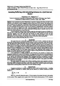
Figure 1: Single phase test, phase to phase Star - delta connected windings
Figure 2: Single phase test, phase to phase Delta – star connected windings From table 2 comparing the values obtained like a 3 x 3 matrix with almost uniform diagonal, the values from the diagonal (223,215 and 220 volts) were the voltages across the generator set terminal when connected to the transformer. Thus, equation (8) below is true and acceptable. yn + bn ≅ rn rn + bn ≅ yn rn + yn ≅ bn
-
(8)
Side
Applied Voltage in kV
Resistance value in MΩ
XLPE cable +HV-E
5kV
300MΩ
XLPE cable +HV-LV
5kV
300MΩ
XLPE cable +LV-E
1kV
200MΩ
Table 3: Insulation Resistance Test Result (Sub-station 1). Remark: These value obtained are acceptable, hence the insulation resistance test was okay (safe) If we plot a graph of LV-side (phase-to-phase) against HV-side (phase-to-phase) from table 1, we have
www.iosrjournals.org
42 | Page
Performance Test of Faulty Distribution Transformers along the Streets and Roads of Port Harcourt
Graph 1. A graph of LV-side against HV-side. The gradient of the graph is equal to the transformation ratio of the transformer. 8.6−8.1 228 −215
=
0.5 13
= 0.038
Check: for 11/0.415kV Distribution transformer LV HV
415
= 11000 = 0.0377
EXCITED
Hence, the transformer was okay From Sub-station 2 HV-side RY YB 24 RY 218 31 YB 212 131 97 BR Avometer Range 750ACV
BR 190 180 223
LV-side ry yb 4.0 0.1 0 1.3 0.1 4.7 Avometer Range 200ACV
br 4.2 1.1 4.7
L rn yn 0 0.2 0.1 0 0.1 0 Avometer Range 200ACV
V-side bn 4.1 1.3 4.5
Table 4: Shows a Single Phase Transformation Ratio Test Result (Sub-station 2)
Excitedvoltage say 230v
Remark: Abnormal transformation ratio, hence transformer not okay –yellow phase was bad. rn tripped tripped Tripped
rn yn bn
LV-side yn test test test
bn Set OFF Set OFF Set OFF
Avometer Range selection: 750ACV
Table 5: shows a single phase step-up ratio test Result (Sub-station 2) Continuity test on windings (Sub-station 2) HV-winding - okay LV- winding –okay Insulation Resistance Test Result (Sub-station 2) windings HV winding + T/F body HV winding –LV neutral LV winding +T/F body
Applied Voltage in kV 5kV 5kV 1kV
Resistance value in MΩ 0.0MΩ 0.0MΩ 0.0MΩ
Table 6: shows insulation Resistance test results Result of Earthing Resistance Test (Sub-station 2) Transformer body – 1.8 ohms LV-neutral – 2.0 ohms Lightening Arrester – 2.2 ohms www.iosrjournals.org
43 | Page
Performance Test of Faulty Distribution Transformers along the Streets and Roads of Port Harcourt Remark: Acceptable Earthing Resistance Phase R-E Y-E B-E
Applied Voltage in kV 5kV 5kV 5kV
Resistance value in MΩ 500MΩ 500MΩ 500MΩ
Duration of measurement 3 mins 3 mins. 3 mins
Table 7: Result of Insulation Resistance Test on HV- cables (Sub-station 2) Phase r-e y-e b-e
Applied Voltage in kV 1kV 1kV 1kV
Resistance value in MΩ 20MΩ 20MΩ 20MΩ
Duration 3 mins 3 mins. 3 mins
Table 8: Result of 0.415kV, 500mm2 single-core cable from transformer to feeder pillar. Instrument used: megger tester.
V.
Discussion
From Table 1 (Sub-station1) above, the single phase transformation ratio test conducted have a remark: The HV-side windings are okay. Also, Table 2 step-up ratio test with remark: LV-side windings are okay. Table 3Insulation Resistance Test Result (Sub-station 1) with remark: The values obtained are acceptable, hence the insulation resistance test was also okay (safe). Looking at the results obtained from Sub-station 2, Table 4: Shows that, the Single Phase Transformation Ratio Test givesa remark: Abnormal transformation ratio, hence transformer not okay –yellow phase was bad. Attable 5, the test underinvestigation: tripped test set OFF - meaning abnormal step-up ratio obtained. Therefore, the Transformer was not safe for power delivery. Also, Continuity test on the windings: HVwinding and LV-winding were okay.Table 6: shows insulation resistance test results with remark: complete insulation breakdown on the HV and LV windings of the transformerat (Sub-station 2).Table 7: Result of Insulation Resistance Test on HV- cableswith remark: Good insulation resistance on all cables phases (Substation 2).Table 8: Results of 0.415kV, 500mm2 single-core cables from transformer to feeder pillar (4.5m). Instrument used: Megger tester. Remark: from the table, the results are acceptable for insulation Resistance. Physical Observation at Sub-Station 2: It was observed that, the tap changer of the transformer was tampered with and changed to tap 4. The tap changer was not properly positioned. In case of Sub-station 1, the tap changer was properly position. Note: Improper positioning of the tap changer of a transformer may adversely affect the transformer, in terms of voltage level, current, etc. therefore care should be taken in the positioning of the tap changer of a transformer.
VI.
Recommendation
From the findings, the transformer with (S/No.LC 73506) at as 26/11/2007 required proper repair or replacement to ease electricity consumer, power outage. The red and yellow phase of the HV and LV windings were burnt. Thus, wrong operation of the tap changer can cause damage to a transformer under use. 2. Distribution transformer along the streets or roads should be properly fenced. 3. Ease access for inspection and maintenance should be put in place for further or routine maintenance 4. Only qualified technician be allowed to carry out routine maintenance and repair on all feeder pillar and transformers. 5. Proper replacement of feeder pillar fuses shall reduce some level of arcing on the fuses holders 6. Wrong application of re-wiring the feeder pillars may cause damage to the transformer as seen on the streets and roads where distribution transformers are installed for service delivery.
VII.
Conclusion
I wish this article gives the entire practical basis required to carry out a performance tests on Distribution Transformers in-service (along a Street or Road) for electricity consumers; however, proper inspection/testing of transformers whether power or distribution should be undertaken on routine maintenance or preventive maintenance to avert the cause(s) of transformer failure due to i. Thief on apparatus ii. Consumers wrong connection iii. Poor earthing system iv. Absent of lightening Arresters. v. Overloading of a transformer. vi. Lightning Surges. vii. Line Surges/External Short Circuit. www.iosrjournals.org
44 | Page
Performance Test of Faulty Distribution Transformers along the Streets and Roads of Port Harcourt viii. Poor Workmanship-Manufacturer. ix. Deterioration of Insulation. x. Moisture. xi. Inadequate Maintenance xii. Sabotage, Malicious Mischief. xiii. Loose Connection Note: Part 2 of this article shall include: Load test, high voltage (33kV) line insulation resistance test, etc.
VIII Acknowledgement Dr. Rowland Uhunmwangho, Head of Department, (Electrical Engineering), University of Port Harcourt, Rivers State, Nigeria
References [1]. [2]. [3]. [4]. [5]. [6]. [7].
DistributionTransformer:http://en.wikipedia.org/w/index.php?title=Distribution_transformer&oldid=570740977Retrieved (January, 2013) William H.B, An Analysis of Transformer Failures, Part 2: Causes, Prevention, and Maximum Service Life, online http://www.hsb.com/thelocomotive/ananalysisoftransformerspart2.aspxRetrieved (January, 2013) http://grouper.ieee.org/.../transformers/.../Short%20circuit%20test%20code%2 Tesla Transformer ltd, (2013).Installation, Commissioning operation & Maintenance: instruction for distribution Transformer ( small &medium capacity), 30-B, industrial area, govindpura Bhopal -462023, Madhya, Phcn, Diobu District (2007). Protection, control and metering (PC&M) section, (Distribution Department) Port Harcourt, Nigeria. Pradesh,india. http://www.teslatransformers.com/images/ommanual.pdf. Theraja, B.L and Theraja, A.K. (2001). A textbook of Electrical Technology , S. Chand & company ltd, Ram Nagar, New Delhi.
www.iosrjournals.org
45 | Page