A WDM-PON with a 40 Gb/s (32 × 1.25 Gb/s) capacity based on wavelength-locked FabryPerot laser diodes Sil-Gu Mun, Jung-Hyung Moon, Hoon-Keun Lee, Jun-Young Kim, and Chang-Hee Lee School of Electrical Engineering & Computer Science, Korea Advanced Institute of Science and Technology, 373-1, Guseong-dong, Yuseong-gu, Daejeon, 305-701, Korea *Corresponding author:
[email protected]
Abstract: We investigate a high capacity WDM-PON based on wavelength locked Fabry-Perot laser diodes. An error-free transmission of 1.25 Gb/s per subscriber was achieved with a flat-top passband AWG and a laser diode with low reflectivity. Then, we demonstrate a WDM-PON of 40-Gb/s capacity of 32 channels over 15 km of single mode fiber. It also shows that color-free operation within conventional C-band wavelength. The observed dispersion penalty after 30 km transmission was 0.5 dB. The demonstrated WDM-PON shows a robust transmission performance on the optical back reflection. ©2008 Optical Society of America OCIS codes: (060.4510) Optical communications; (060.4250) Networks.
References and links 1. 2.
3.
4. 5. 6.
7. 8. 9. 10. 11.
12. 13.
C.-H. Lee, W. V. Sorin, and B. Y. Kim, ”Fiber to the Home Using a PON Infrastructure,” IEEE J. Lightwave Technol. 24, 4568-4583 (2006). A. Banerjee, Y. Park, F. Clarke, H Song, S. Yang, G. Kramer, K. Kim, and B. Mukherjee, ”Wavelengthdivision-multiplexed passive optical network (WDM-PON) technologies for broadband access: a review,” J. Opt. Networking 4, 737-758 (2005). C.-H. Lee, S.-M. Lee, K.-M. Choi, J.-H. Moon, S.-G. Mun, K.-Y. Park, J.-S. Baik, J.-H. Park, M.-H. Kim, and H.-K. Lee, “WDM-PON: a next generation access network,” Asia-Pacific Optical Communications2006 6353-6364 (2006). Z. Xu, Y. J. Wen, W.-D. Zhong, C.-J. Chae, X.-F. Cheng, Y. Wang, C. Lu, and J. Shankar, “High-speed WDM-PON using CW injection-locked Fabry-Pérot laser diodes,” Opt. Express 15, 2953-2962 (2007). F. Payoux, P. Chanclou, and N. Genay, “WDM-PON with colorless ONUs,” in Proceedings of the Optical Fiber Communication and Conference, Paper OTuG5 (2007). Y.-S. Liao and G.-R. Lin, “22-Channel Detuning Capacity of a Side-Mode Injection Locked FPLD for Directly Modulated 2.5Gbit/s DWDM-PON,” in Proceedings of the Optical Fiber Communication and Conference, Paper OMS8 (2007). H. D. Kim, S.-G. Kang, and C.-H. Lee, “A low-cost WDM source with an ASE injected Faby-Pérot semiconductor laser,” IEEE Photon. Technol. Lett. 12, 1067–1069 (2000). C.-H. Lee, S.-M. Lee, K.-M. Choi, J.-H. Moon, S.-G. Mun, K.-T. Jeong, J. H. Kim, and B. Kim, “ WDMPON experiences in Korea (Invited paper),” J. Optic. Networking 6, 451-464 (2007). H.-J. Park, H. Yoon, T. Park, S.-J. Park, and J. H. Kim, ”Recent Research Activities of WDM-PON in Korea,” in Proceedings of the Optical Fiber Communication and Conference, Paper OWL1 (2007). S.-M. Lee, M.-H. Kim, and C.-H. Lee, “Demonstration of a Bidirectional 80-km-Reach DWDM-PON With 8-Gb/s Capacity,” IEEE Photon. Technol. Lett. 19, 405-407 (2007). K.-Y. Park, J.-S. Baik, T.-W. Oh, and C.-H. Lee, “Intensity noise suppression and 1.25 Gb/s transmission using a wave-length locked Fabry-Perot laser diode with filtered ASE injection,” Optoelectronics and Communication Conference 200-201 (2004). S.-G. Mun and C.-H. Lee, “An optimization method for the decision threshold level in optical receivers for WDM-PONs,” Asia-Pacific Optical Communications 6354-77 (2006). J.-H. Moon, K.-M. Choi, S.-G. Mun, and C.-H. Lee, “Effects of Back-Reflection in WDM-PONs Based on Seed Light Injection,” IEEE Photon. Technol. Lett. 19, 2045-2047 (2007).
#95166 - $15.00 USD
(C) 2008 OSA
Received 17 Apr 2008; revised 3 Jul 2008; accepted 3 Jul 2008; published 14 Jul 2008
21 July 2008 / Vol. 16, No. 15 / OPTICS EXPRESS 11361
1. Introduction A wavelength division multiplexed-passive optical network (WDM-PON) has been accepted as the ultimate solution for access networks, since it provides unlimited bandwidth to the subscribers through a virtual point-to-point connectivity [1]. In implementation of WDMPON, a cost-effective color-free optical source is essential. Recently, various optical sources have been proposed [1]-[6]. Among them, WDM-PONs based on wavelength locked FabryPerot laser diodes (F-P LDs) [7] was mature to commercialize and have deployed in Korea Telecom (KT) network [8, 9]. It presented a long reach transmission at 8 Gb/s capacity over 80 km of single mode fiber (SMF) [10] and confirmed a feasibility of 1.25 Gb/s transmission [11]. However, there is no report on the pure color-free operation of WDM-PON at 1.25 Gb/s per channel with 100 GHz channel spacing. In this paper, we investigate a high capacity WDM-PON based on the wavelength locked F-P LDs. The channel spacing and the dedicated bandwidth per subscriber are 100 GHz and 1.25 Gb/s, respectively. The bandwidth of an arrayed waveguide grating (AWG) and front facet reflectivity of an F-P LD are major parameters that determine the transmission performance while the back reflection and dispersion show relatively small effects. We demonstrated a WDM-PON with a 40-Gb/s capacity over a conventional C-band. The 32 channel WDM-PON show a color-free operation with a small penalty induced by dispersion and optical back reflection. RN
CO (OLT)
ONTs
ONT 1
Upstream
Rx
ONT K
Tx
...
. ..
C y clic A W G
C BLS
...
Rx
C yc lic AW G
.. .
15 km SMF
Tx
15 km SMF
1.25G b /s P R B S
Rx
ONT 32
Tx
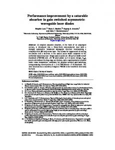
Fig. 1. Experimental setup of 32 channels DWDM-PON based on wavelength-locked F-P LD.
2. Demonstration of 40 Gb/s WDM-PON 2.1 Experimental set up A WDM-PON based on wavelength locked F-P LDs for upstream transmission is shown in Fig. 1. It consists of a broadband light source (BLS) for a seed light, AWGs, and receivers at an optical line terminal (OLT). The transmission feeder fiber connects the OLT and an AWG at the remote node (RN). Then, an optical network terminal (ONT) that has an F-P LD is connected to the output port of the AWG at RN through a distribution fiber. The BLS is realized by using amplified spontaneous emission (ASE) from Er-doped fiber pumped by 1480 pump laser. All F-P LDs which used in transmitters were packaged with a conventional transistor outlook (TO)-can type. We picked up an F-P LD randomly for each channel. The FP LD was modulated at 1.25 Gb/s with pseudorandom bit sequence (PRBS) with a length of 231-1. 2.2 Effect of AWG passband and reflectivity of an F-P LD To investigate transmission performance at various circumstances, we used two types of AWGs with channel spacing of 100 GHz. The first one has Gaussian passband with 3-dB bandwidth of 0.4 nm, while the other has flat-top passband with 3-dB bandwidth of 0.61 nm. We also used two different type of F-P LD with front facet reflectivity of 1 % and 0.1 %. Both
#95166 - $15.00 USD
(C) 2008 OSA
Received 17 Apr 2008; revised 3 Jul 2008; accepted 3 Jul 2008; published 14 Jul 2008
21 July 2008 / Vol. 16, No. 15 / OPTICS EXPRESS 11362
Table 1. Four experimental set according to AWG passband type and front-facet reflectivity of F-P LD used in the Tx.
AWG
Front facet reflectivity of an F-P LD used in Tx
Experimental Set 1
Gaussian passband
1%
Experimental Set 2
Gaussian passband
0.1 %
Experimental Set 3
Flat-top passband
1%
Experimental Set 4
Flat-top passband
0.1 %
Best (total power : -5.1 dBm) Worst (total power : -5.1 dBm) Best (total power : -2.6 dBm) Worst (total power : -2.6 dBm)
(a) Experimental Set 1 (a)
Best (total power : -5.1 dBm) Worst (total power : -5.1 dBm) Best (total power : -2.6 dBm) Worst (tot al power : -2.6 dBm)
(b) Experimental Set 2
Best (total power : -5.1 dBm)
Best (tot al power : -5.1 dBm)
Worst ( total power : -5.1 dBm)
Worst ( total power : - 5.1 dBm)
Best (total power : -2.6 dBm) Worst (total power : -2.6 dBm)
(c) Experimental Set 3
(d) Experimental Set 4
Fig. 2. Measured BER result in case of both best performance and worst performance when we use experimental set in Table. 1.
F-P LDs have a mode spacing of 0.57 nm. For optical receiver at the OLT, the decision threshold level was automatically changed to take into account broad ’1’ level noise due to incoherent light source injection [12]. To consider the transmission performance limited by the AWG bandwidth and the front facet reflectivity of F-P LD, we do not insert the feeder fiber and the distribution fiber in Fig. 1. The detailed experimental set is summarized in Table. 1. In addition, we used AWGs with same bandwidth both the CO and the RN. First of all, when we selected Gaussian passband AWG and an F-P LD with 1 % reflectivity for low insertion loss and a possibility of high temperature operation. It may be noted that the F-P LD with a low front facet reflectivity gives higher gain with high temperature dependency. The measured bit error rate (BER) curves are shown in Fig. 2(a). The BER curves were taken at the best case and the worst case within one mode spacing of FP LD to investigate color-free operation. Here, the best case was observed when the wavelength of injection ASE was matched with the lasing wavelength of the F-P LD, while the worst case was observed when it was between the lasing modes. The BER curves show error floors at BER of 10-9 for the best case and 10-7 for the worst case. The injection ASE power to the F-P LD was -5.1 dBm. To investigate BER with a higher injection ASE power,
#95166 - $15.00 USD
(C) 2008 OSA
Received 17 Apr 2008; revised 3 Jul 2008; accepted 3 Jul 2008; published 14 Jul 2008
21 July 2008 / Vol. 16, No. 15 / OPTICS EXPRESS 11363
we increased injection ASE power as 2.5 dB to have the total injection power of -2.6 dBm. However, improvement in BER curve was not significant as shown in Fig. 2(a). To improve the BER performance, we changed the F-P LD with 1 % reflectivity to an F-P LD with 0.1 % reflectivity. As shown in Fig. 2(b), the error floor levels were reduced to below 10-10 and 10-8 for the best case and the worst case when injection ASE power is -5.1 dBm, respectively. By increasing the injection ASE power to -2.6 dBm, we improved the BER performance slightly. Based on these results, we concluded that it is not easy to have an error free transmission with Gaussian passband AWG at the channel spacing of 100 GHz. It can be explained that either a high relative intensity noise (RIN) of the injected ASE light or insufficient noise suppression in F-P LD. It stated that it is not easy to have an error-free transmission even we use a reflective semiconductor optical amplifier (RSOA) instead of the F-P LD. 0
P o w e r (d B m
-10
ch8
ch1
ch16
ch32
ch24
-20 -10
-30 -20
-40 -30
-50 1525
1535
1535
1540
1545
1555
1565
Wavelength (nm)
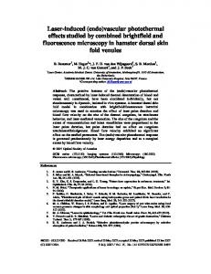
Fig. 3. Measured locked spectra of 32 WDM channel.
We changed the AWGs with flat-top passband to improve transmission performance. The measured BER curves are shown in Fig. 2(c) in case of an F-P LD with 1% reflectivity. We observed a possibility of an error free transmission, since the sign of the error floor was diminished. We clearly observed an error-free transmission at the best case. Finally, we observed an error free transmission at injection power of -5.1 dBm by changing the F-P LD with 0.1 % reflectivity regardless of the injection position as shown in Fig. 2(d). Here, the injection position means the wavelength of the injected ASE with respect to a lasing mode of the F-P LD. It should be noted that the measured minimum injection ASE power for an error free transmission was -9.6 dBm (-16 dBm/0.2 nm). 2.3 40 Gb/s WDM-PON experiment Based on these results, we selected AWGs with flat-top passband and F-P LDs with 0.1 % reflectivity for demonstration of 32-channel WDM-PON. The temperature of the F-P LD was fixed at 43 using a heater for the experimental convenience. As the previous experiments, each channel carries a 1.25 Gb/s PRBS with a length of 231-1. We also inserted the feeder fiber of 15 km between CO and RN. The injected ASE powers into the F-P LDs were ranged from -12 dBm/0.2 nm to -13.5 dBm/0.2 nm (Total powers were ranged from -5.6 dBm to -7.1 dBm). The difference value came from the transmission loss of the AWG and spectral profile of the BLS output. Since the transmission bit rate per channel is 1.25 Gb/s, the total capacity of the WDM-PON is 40 Gb/s.
℃
#95166 - $15.00 USD
(C) 2008 OSA
Received 17 Apr 2008; revised 3 Jul 2008; accepted 3 Jul 2008; published 14 Jul 2008
21 July 2008 / Vol. 16, No. 15 / OPTICS EXPRESS 11364
-15
Power (dBm)
-17 -19 -21 -23 -25 0
4
8
12
16
20
24
28
32
channel # Fig. 4. Measured locked power of 32 channels at the receiver side.
Fig. 5. Measured BER result of 32 channel after 15 km transmission for ch1~ch32.
We measured optical spectra of 32 channels at the output of the RN. As shown in Fig. 3, there are diverse locked spectral characteristics. This is caused by differences in the injection ASE power and injection position with respect to the lasing mode of the F-P LD. We also measured received optical power after passing through an AWG at CO and the result is represented in Fig. 4. The measured power ranged from –17.4 dBm (maximum value at channel #18) to -22 dBm (minimum value at channel #16). We measured BER curves for all 32 channels after transmission of 15 km SMF. All BER curves show an error free transmission as shown in Fig. 5. The sensitivities were ranged from -24.8 dBm to -26.0 dBm at the BER of 10-12. The sensitivity difference between channels is only less than 1 dB. It implies that the signal quality of the transmitted data is fairly uniform under uncontrolled injection ASE power and injection position for each F-P LD. This feature implies a feasibility color-free operation of ONTs. To confirm the color-free operation, we randomly picked up an ONT. Then, it was used for all 32 channels. The measured spectrum of the free-running F-P LD used in ONT and the wavelength locked output for all 32 channels are shown in Fig. 6(a), (b), respectively. The output power and spectral shape changes as the used channel varies. The measured BER curves for all 32 channels are shown in Fig. 7. The sensitivity difference was less than 1 dB regardless of the used channel. As shown in Fig. 6(a), the center wavelength of the F-P LD is around 1533 nm. This F-P LD showed the color-free operation over wavelength range of 1530 – 1560 nm which is limited by the available injection power. Thus, the color-free wavelength range may be widen between 1506 nm (1533 - 27) and 1560 nm (1533 + 27).
#95166 - $15.00 USD
(C) 2008 OSA
Received 17 Apr 2008; revised 3 Jul 2008; accepted 3 Jul 2008; published 14 Jul 2008
21 July 2008 / Vol. 16, No. 15 / OPTICS EXPRESS 11365
-5
0
0
-10
-10
P o w e r(d B m
P o w er(d B m
-1 5
-20 -30 -40
-2 5 1 535
1 540
-20 -30 -40
-50 1525
1535
1545 1555 Wavelength(nm)
(a)
1565
-50 1525
1535
1545
1555
1565
Wavelength(nm)
(b)
Fig. 6. (a) Spectrum of free running F-P LD, (b) Locked spectra when we used identical ONT with F-P LD which depicts in (a).
As we injected the spectrum sliced ASE into an F-P LD, the linewidth of the wavelength locked output is much broader than a typical single mode output. Thus, the dispersion penalty is the one of concern in a WDM-PON with wavelength locked F-P LDs. To investigate the dispersion effect, we measured the dispersion penalty as a function of the transmission length. To do that, we used channel 18 that shows maximum received power. We added an extra transmission fiber between the AWG output at the CO (see Fig. 1(a)) and the optical receiver
Fig. 7. Measured BER result when we used an identical ONT as Tx from channel 1 to channel 32.
to maintain the injection ASE power into the F-P LD as a constant. The measured BER curve as a function of the extra fiber length is shown in Fig. 8. The dispersion penalty up to 30 km transmission was less than 0.5 dB. The measured linewidth of the wavelength locked F-P LD output was 0.52 nm for widest case. The dispersion-limited transmission distance can be
·
estimated based on the BL product which is approximately 56.56 Gb/s km. Thus, the transmission length for 1 dB penalty can be 45 km. Besides the dispersion effect, degradation of system performance due to optical back reflection is one of the major concerns for WDM-PON with a seed light source [13]. Therefore, we investigated optical back reflection effects for the implemented 32 channel
#95166 - $15.00 USD
(C) 2008 OSA
Received 17 Apr 2008; revised 3 Jul 2008; accepted 3 Jul 2008; published 14 Jul 2008
21 July 2008 / Vol. 16, No. 15 / OPTICS EXPRESS 11366
+ 5 km (Total : 20 km) +10 km (Total : 25 km) +15 km (Total : 30 km) Back-to-back
Fig. 8. Dispersion effect as the fiber length is increased (in case of channel 18).
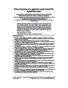
WDM-PON. We make use of the following equation for noise distribution of the “mark” level; ∞ 2E 2 E2 2 σ reflections = 21 × P1 + 22 × P2 × ∑ (2− n × 10n (G + R ) /10 ) =0 n E0 E0 where E0 , E1 , E2 are electrical fields of the signal, the reflected field by the back-reflection of the injected seed light to the CO (reflection-I), and the reflected field by the back-reflection of the modulated upstream signal to the ONU (reflection-II), respectively. P1 is the normalized power spectral density of the beating noise within the receiver bandwidth due to beating between the signal and the reflected field by reflection-I. P2 is that from the signal and the reflected field by reflection-II. G is the ONU gain and R is the optical return loss. By using the measured the narrowest linewidth of 0.33 nm and the RIN of -110 dB/Hz, we calculated achievable Q-factor as a function of the effective back reflection coefficient as shown in Fig. 9. We also made use of a measured ONU gain for this simulation. The ONU gain of 10 dB gives the output signal power of -3 dBm. We can achieve Q-factor greater than 16.9 dB (this is required Q-value for BER 10-12) although the back reflection is as much as -20 dB. We confirmed that this prediction with experiment as indicated by rectangular box. Thus, the proposed WDM-PON based on wavelength locked F-P LD is robust on the optical back reflection due to broad linewidth of the injected ASE light. For comparison, we also plotted both the simulation and experimental result with a coherent source (DFB LD) as a seed light. The WDM-PON with wavelength locked F-P LD shows high immunity to optical back reflection. 3. Discussion and conclusion The capacity of demonstrated WDM-PON was 40 Gb/s over 15 km of a SMF. However, the transmission length was limited by the available injection power as seen in the received power and receiver sensitivity. In addition, the dispersion penalty over 30 km transmission was 0.5 dB. Thus, we can extend the transmission length with a high power BLS. Moreover, the transmission length can be extended further by employing a forward error correction (FEC). It may be noted that FEC can be also used to reduce the injection ASE power. The scalability with respect to number of channels depends on the gain spectrum of the F-P LD and the wavelength band of BLS. We believe that we can expand up to 68 channels since the bandwidth of the BLS and F-P LD are over 54 nm (54 nm/0.8 nm = 67.5 channel). To have higher bit rate per channel, we need higher injection power and/or less noise in the injected ASE source. A proper operation of the F-P LD and/or RSOA having the high noise suppression is also helpful for higher speed operation.
#95166 - $15.00 USD
(C) 2008 OSA
Received 17 Apr 2008; revised 3 Jul 2008; accepted 3 Jul 2008; published 14 Jul 2008
21 July 2008 / Vol. 16, No. 15 / OPTICS EXPRESS 11367
30 Simulation (Incoherent source) Experiment (Incoherent source)
Q factor (dB)
25
Simulation (Coherent source) Experiment (Coherent source)
20
15
10
5 -40
-35
-30
-25
-20
-15
Reflectivity (dB) Fig. 9. Reflection effect according to the reflectivity both incoherent light source and coherent light source (simulation and experiment result).
We only demonstrated the upstream transmission in this paper, since it has more technical issues such as back scattering induced penalty and the attenuation of the BLS power compared with the downstream transmission. We are expecting a very small penalty induced by crosstalk between the downstream transmission and the upstream transmission because we use a different wavelength band for the transmission band. For example, we could use C-band for the upstream transmission and E- or L-band for the downstream transmission. In conclusion, we studied on effect of AWG passband profile and front facet reflectivity of F-P LD in wavelength locked F-P LDs. The AWG with a flat-top passband brought a better BER performance due to the decreased RIN of the injected ASE. The BER performance improved further by decreasing the front facet reflectivity of the F-P LD. Based on these results, we demonstrated a WDM-PON with 40 Gb/s capacity, guaranteeing a 1.25 Gb/s dedicated bandwidth per subscriber over 15 km of a SMF. It also shows that full color-free operation within conventional C-band wavelength. The demonstrated WDM-PON shows good immunity to the dispersion and optical back reflection. Acknowledgment This work was supported in part by the National Research Laboratory (NRL) program of Ministry of Science and Technology (MOST).
#95166 - $15.00 USD
(C) 2008 OSA
Received 17 Apr 2008; revised 3 Jul 2008; accepted 3 Jul 2008; published 14 Jul 2008
21 July 2008 / Vol. 16, No. 15 / OPTICS EXPRESS 11368