Petri nets – an Application in Digital Circuits Shruti Jain Department of Electronics and Communication Engineering Jaypee University of Information Technology, Solan-173215, India 1 E-mail :
[email protected]
Pradeep K. Naik Department of Bioinformatics Jaypee University of Information Technology, Solan-173215, India 1 E-mail :
[email protected]
Abstract :
Synthetic biology has been used to describe an approach to biology which attempts to design and construct deliberate biological systems that can be investigated experimentally, which are otherwise very expensive and practically challenging. One of the central features of synthetic biology is the appreciation of the knowledge from science and engineering disciplines for the better design and understanding of synthetic networks. In this paper we will study regarding Petri nets and how digital circuits can be implemented using Petri nets. This paper highlights an emerging field known as synthetic biology that envisions integrating designed circuits into living organisms in order to instruct them to make logical decisions based on the prevailing intracellular and extra cellular conditions and produce a reliable behavior. The networks in a system can be dissected into small regulatory gene circuit modules. Synthetic biology attempts to construct and assemble such modules gradually, plug the modules together and modify them, in order to generate a desired behavior. Using biological circuit, we can produce a new concentration gradient that has twice the frequency. If ‘1’ is represented by a concentration of the chemical within the threshold, and a ‘0’ is represented by a concentration outside the threshold, then we can represent any two digit binary number. Thus, we can differentiate separate regions at certain distances away from a point source. In this paper we will discuss how to make Logic gates (AND, OR, NOT) using Petri net. Using this approach we can design any Boolean equation.
Categories and Subject Descriptors B.6.1 and D.2.2 [Design Styles and design Tools and Techniques]: Cellular arrays and automata, Combinational Logic, Logic arrays, parallel circuits, Sequential Circuits, Petri nets
Keywords : Petri nets, Places, Transitions, Logic Gates 1. INTRODUCTION : Petri nets, as graphical and mathematical tools, provide a uniform environment for modeling, formal analysis, and design of discrete event systems. One of the major advantages of using Petri net models is that the same model is used for the analysis of Permission to make digital or hard copies of all or part of this work for personal or classroom use is granted without fee provided that copies are not made or distributed for profit or commercial advantage and that copies bear this notice and the full citation on the first page. To copy otherwise, or republish, to post on servers or to redistribute to lists, requires prior specific permission and/or a fee. ICWET’10, February 26–27, 2010, Mumbai, Maharashtra, India. Copyright 2010 ACM 978-1-60558-812-4…$5.00. ISBN - 978-1-60558-812-4
Sunil V. Bhooshan Department of Electronics and Communication Engineering Jaypee University of Information Technology, Solan-173215,India 1 E-mail :
[email protected]
behavioral properties and performance evaluation, as well as for systematic construction of discrete- event simulators and controllers. Petri nets were named after Carl A. Petri who created in 1962 a net-like mathematical tool for the study of communication with automata [1, 2]. A Petri net (also known as a place/transition net or P/T net) is one of several mathematical modeling languages for the description of discrete distributed systems. A Petri net is a directed bipartite graph, in which the nodes represent transitions (i.e. discrete events that may occur, signified by boxes or bars), places (i.e. conditions, signified by circles), and directed arcs (that describe which places are pre- and/or post conditions for which transitions, signified by arrows). Their further development was facilitated by the fact that Petri nets can be used to model properties such as process synchronization, asynchronous events, concurrent operations, and conflicts or resource sharing [3, 4]. These properties characterize discreteevent systems whose examples include industrial automated systems, communication systems, and computer-based systems. These, and other factors discussed in this paper, make Petri nets a promising tool and technology for application to Industrial Automation. With the help of Petri nets we can design universal gates or Logic gates which are used in Digital logic life. In this paper we will discuss AND, OR and NOT gate using Petri nets and how to implement those circuits on Boolean expression.
2. DESCRIPTION OF PETRI NETS Petri nets as graphical tools provide a powerful communication medium between the user, typically requirements engineer, and the customer. Complex requirements specifications, instead of using ambiguous textual descriptions or mathematical notations difficult to understand by the customer, can be represented graphically using Petri nets. This combined with the existence of computer tools allowing for interactive graphical simulation of Petri nets, puts in hands of the development engineers it powerful tool assisting in the development process of complex systems [1, 2, 3] a mathematical tool, a Petri net model can be described by a set of linear algebraic equations, or other mathematical models reflecting the behavior of the system. This opens a possibility for the formal analysis of the model. This allows one to perform a formal check of the properties related to the behavior of the underlying system, e.g., precedence relations amongst events, concurrent operations, appropriate synchronization, and freedom from deadlock, repetitive activities, and mutual exclusion of shared resources, to mention some. The simulation based model validation can only produce a limited set of states of the modeled system, and thus can only show presence (but not absence) of errors in the model, and its underlying requirements specification. Petri nets were used to model real-time fault tolerant and safety-
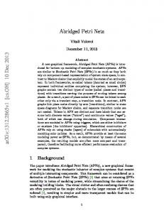
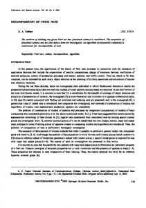
critical systems in. Petri nets, as a mathematical tool, allow for the performance evaluation of the modeled systems. Both deterministic and stochastic performance measures can be evaluated by using a broad class of Petri net models incorporating in their definitions deterministic and/or probabilistic time functions [5, 6] performance evaluation can be conducted using either analytical techniques, based on solving the underlying (semi)-Markov processes, or discrete event simulation. The use of models which incorporate time functions having probabilistic distributions allows one to obtain production rates for manufacturing system models, throughput, delays, capacity for communication and microprocessor system models, as well as critical resource utilization and reliability measures for these and other systems. In recent years, this class of Petri net models has been extensively used to model and study analytically performance of multiprocessor systems, multiprocessor system buses DSP communication channels, parallel computer architectures as well as parallel distributed algorithms [7, 8]. Petri nets with time extensions, combined with heuristic search techniques, were used to model and study scheduling problems involving manufacturing systems as well as robotic systems. The robotic assembly and trajectory planning using Petri nets were presented in. Petri nets with time extensions were also used to model and analyze dynamics of continuous chemical processes. The continuous time and discrete-event process control was modeled and analyzed in [9, 10]. A Petri net may be identified as a particular kind of bipartite directed graph populated by three types of objects. These objects are places, transitions, and directed arcs connecting places to transitions and transitions to places. Pictorially, places are depicted by circles and transitions as bars or boxes. A place is an input place to a transition if there is a directed arc connecting this place to the transition. A place is an output place of a transition if there is a directed arc connecting the transition to the place. In its simplest form, a Petri net may be represented by a transition together with its input and output places. This elementary net may be used to represent various aspects of the modeled systems. For instance, input (output) places may represent preconditions (post conditions), the transition an event. Input places may represent the availability of resources, the transition their utilization, output places the release of the resources. An example of a Petri net is shown in Fig. 1. This net consists of five places, represented by circles, four transitions, depicted by bars, and directed arcs connecting places to transitions and transitions to places. In this net, place p1 is an input place of transition t1. Places p2, and p3 are output places of transition t1.
In order to study dynamic behavior of the modeled system, in terms of its states and their changes, each place may potentially hold either none or a positive number of tokens, pictured by small solid dots, as shown in Fig. 1. The presence or absence of a token in a. place can indicate whether a condition associated with this place is true or false, for instance. For a place representing the availability of resources, the number of tokens in this place indicates the number of available resources. At any given time instance, the distribution of tokens on places, called Petri net marking, defines the current state of the modeled system. A Petri net containing tokens is called a Marked Petri net. For example, in the Petri net model shown in Fig. 1, M =(1,0, 0, 0,0,)T. Formally, a Petri net can be defined as follows: PN = (P, T, I, O, M0); where 1. P = {p1, p2, ... . pm} is a finite set of places, 2. T = {t1, t2... .., tn} is a finite set of transitions, P U T ≠ Φ, and P ∩ T = Φ, 3. I : (P x T) →N is an input function that defines directed arcs from places to transitions, where N is a set of nonnegative integers, 4. O : (P x T') → N is an output function which defines directed arcs from transitions to places, and 5. Mo : P → N is the initial marking.
Role of a token Tokens can play the following roles: • a physical object, for example a product, a part, a drug, a person; • an information object, for example a message, a signal, a report; • a collection of objects, for example a truck with products, a warehouse with parts, or an address file; • an indicator of a state, for example the indicator of the state in which a process is, or the state of an object; • an indicator of a condition: the presence of a token indicates whether a certain condition is fulfilled.
Role of a place • a type of communication medium, like a telephone line, a middleman, or a communication network; • a buffer: for example, a depot, a queue or a post bin; • a geographical location, like a place in a warehouse, office or hospital; • a possible state or state condition: for example, the floor where an elevator is, or the condition that a specialist is available.
Role of a transition • an event: for example, starting an operation, the death of a patient, a change seasons or the switching of a traffic light from red to green; • a transformation of an object, like adapting a product, updating a database, or updating a document; • a transport of an object: for example, transporting goods, or sending a file.
Figure 1: Example of graphical representation of Petri Net
If I(p, t) = k (O(p, t) = k), then there exist k directed (parallel) arcs connecting place p to transition t (transition t to place p). If I (p, t) = 0 (O(p, t) = 0), then there exist no directed arcs connecting p to t. (t to p). Frequently, in the graphical representation, parallel arcs connecting a place (transition) to a transition (place) are represented by a single directed arc labeled with its multiplicity, or
weight k. This compact representation of multiple arcs is shown in Fig. 2.By changing distribution of tokens on places, which may reflect the occurrence of events or execution of operations, for instance, one can study dynamic behavior of the modeled system. The following rules are used to govern the flow of tokens. Enabling Rule. A transition t is said to be enabled if each input place p of t contains at least the number of tokens equal to the weight of the directed arc connecting p to t. Firing Rule : 1. An enabled transition t may or may not fire depending on the additional interpretation, and 2. A firing of an enabled transition t removes from each input place p the number of tokens equal to the weight of the directed arc connecting p to t. It also deposits in each output place p the number of tokens equal to the weight of the directed arc connecting t to p.
Figure 4 : Petri net with an inhibitor arc.
3. THE LOGIC OF LIFE : A digital technology usually starts with Boolean logic gates— devices that operate on signals with two possible values, such as true and false, 1 and 0. There are three basic logic gates: AND, OR, NOT.
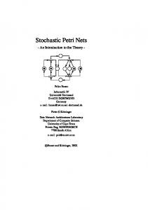
3.1 An AND GATE : An AND gate has two or more inputs and one output; the output is true only if all the inputs are true. The symbol, switching circuit and truth table for AND gate shown in Fig. 5. Petri net implementation of AND gate is shown in Figure 6. A, B and C shows places which are represented by circles, in which A and B are inputs which C is the output, while t represents the transition.
Figure 2: (a) Multiple arcs (b) Compact representation of multiple arcs The enabling and firing rules are illustrated in Fig. 3. In Fig. 3 (a), transition t1 is enabled as the input place p1of transition t1 contains two tokens, and I (p1, t1) = 2. The firing of the enabled transition t1 removes from the input place p1 two tokens as I (p1, t1) = 2, and deposits one token in the output place p3, O(p3, t1) = 1. and two tokens in the output place p2, O(p2 , t1) = 2. This is shown in Fig. 3(b).
Fig.5: Switching Circuit and Truth table for AND gate
Figure 3 : (a) Transition t1 is enabled (b) enabled transition t1 fires The modeling power of Petri nets can be increased by adding the zero testing ability, i.e., the ability to test whether a place has no token. This is achieved by introducing an inhibitor arc. The inhibitor arc connects an input place to a transition, and is pictorially represented by an arc terminated with a small circle. A Petri net with an inhibitor is shown in Fig. 4. The presence of an inhibitor arc connecting an input place to a transition changes the transition enabling conditions. In the presence of the inhibitor arc, a transition is regarded as enabled if each input place, connected to the transition by a normal arc (an arc terminated with an arrow), contains at least the number of tokens equal to the weight of the arc, and no tokens are present on each input place connected to the transition by the inhibitor arc. The transition firing rules are the same as for normally connected places. The firing, however, does not change the marking in the inhibitor arc connected places
Fig 6 : Petri net representation of AND gate
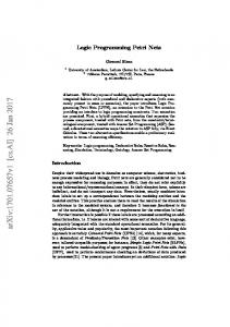
3.2 An OR GATE : An OR gate is similar except that the output is true if any of the inputs are true. The symbol, switching circuit and truth table for OR gate is shown in Fig.7. Petri net implementation of OR gate is shown in Figure 8.
3.3 NOT GATE : The simplest of all gates is the NOT gate, which takes a single input signal and produces the opposite value as output: true becomes false, and false becomes true. The symbol, switching circuit and truth table for NOT gate is shown in Fig.9. Petri net implementation of NOT gate is shown in Figure 10.
Figure.7 : Switching Circuit and Truth table for OR gate Figure 11 : Represents Boolean equation.
4. CONCLUSION :
Figure 8 : Petri net representation of OR gate
We had successfully designed the basic gates using Petri nets. So with the help of basic gates we can design any universal gate of Boolean equation. So we can design any digital circuit with the help of Petri nets. Synthetic biology attempts to construct and assemble such modules gradually, plug the modules together and modify them, in order to generate a desired behavior. We can engineer bio-circuits to meet design specifications, using genetic engineering. This approach is similar to design space exploration in traditional VLSI, but takes into account biological knowledge obtained through experiments. We also provide insight into the robustness of bio-circuits in the presence of noise. 6. REFERNECES :
Figure. 9 : Switching Circuit and Truth table for NOT gate
Figure 10 : Petri net representation of NOT gate. By using basic logic gates (AND, OR, NOT) we can design universal gates i.e. NAND, NOR gate and also we can solve any Boolean expression. Example showing Exclusive OR gate can be represented as shown in Figure 11.
[1] Alla, H, David, R. (1998). Continuous and hybrid Petri nets. J Circuits Syst Comput, 8, 159-188. [2] Genrich, H., Küffner, R., Voss, K., 2000. Executable Petri net models for the analysis of metabolic pathways. In: Proceedings of the 21st International Conference on Application and Theory of Petri Nets, Workshop Proceedings Practical Use of High-level Petri Nets, Aarhus. pp. 1–14 [3] Genrich, H., Küffner, R. and Voss, K. (2001). Executable Petri net models for the analysis of metabolic pathways. International Journal on Software Tools for Technology Transfer, 3(4), 394404. [4] Heiner, M., Koch, I., Voss, K., 2001. Analysis and simulation of steady states in metabolic pathways with Petri nets. In: Proceedings of the CPN Workshop, University of Aarhus. pp. 15– 34. [5] Hofestaedt, R. (1994). A Petri Net Application of Metabolic Processes. Journal of System Analysis, modeling and Simulation 16, 113-122. [6] Murata, T., Petri Nets: Properties, Analysis and Applications, Proceedings of the IEEE, Vol.77, No.4, April 1989, pp.541-580. [7] Peterson, J.L., Petri Net Theory and the Modeling of Systems, PRENTICE-HALL, Englewood Cliffs, N.J., 1981. [8] Reddy, V. N., Liebman, M. N. and Mavrovouniotis, M. L. (1996). Qualitative analysis of biochemical reaction systems. Comput. Biol. Med. 26, 9-24. [9] Matsuno, H., Doi, A., Nagasaki, M. and Miyano, S. (2000). Hybrid Petri net representation of gene regulatory network. Proc. Pacific Symposium on Biocomputing 2000, 338-349. [10]Nagasaki, M., Doi, A., Matsuno, H., Miyano, S.? (2004). A Versatile Petri Net Based Architecture for Modeling .Simulation of Complex Biological Processes, Genome Informatics, 15(1).