Phase correlation method for subpixel in-plane vibration measurements of MEMS by stroboscopic microscopy B. Serio1*, J. J. Hunsinger2, D. Teyssieux1, B. Cretin1 1)
FEMTO-ST/CNRS UMR 6174, LPMO 32 avenue de l’Observatoire, 25044 Besançon Cedex 2)
FEMTO-ST/CNRS UMR 6174, CREST Parc technologique, 2 avenue Jean Moulin, 90000 Belfort *Corresponding author:
[email protected], phone: +33 (0)3 81 85 39 99 ABSTRACT Accurate estimation of displacement between successive images is a significant topic in the measurement of in-plane vibrations of microscopic objects such as micro-actuators. Actual subpixel motion estimation algorithms require the interpolation of interpixel values which undesirably increases the overall complexity and data flow and deteriorates estimation accuracy. Methods that do not use interpolation for achieving subpixel accuracy are scarcer in the literature. One approach for subpixel movement estimation without interpolation is based on phase correlation algorithm. This algorithm estimates the relative shift between two image blocks by means of a normalized crosscorrelation function computed in the 2-D spatial Fourier domain. Indeed, the method is based on the Fourier shift theorem. The cross power spectrum of two images, containing subpixel shifts, is a polyphase decomposition of a Dirac delta function. By estimating the sum of polyphase components one can then determine subpixel shifts along each axis. Phase correlation is the state of the art for interpolation-free subpixel shift measurement between two frames, but this method is strictly limited to subpixel shifts. So, we have implemented this method using a standard optical microscope in order to observe subpixel translations with high spatial resolution measurements (down to 1 nm in the best cases). In this paper, we propose an application of this method to characterize the vibration mode shapes of a small silicon beam used in near-field acoustic microscopy. Harmonic movements of a few tens of nanometers are measured and presented. Keywords : MEMS, in-plane vibration measurement, subpixel accuracy, motion estimation, shift measurement, phase correlation
1. INTRODUCTION Micro-Electro-Mechanical-Systems (MEMS) for actuator and sensor applications are being applied increasingly in automobile or aerospace industries for instance. Most MEMS, like accelerometers, gyros, pressure sensors have their functionality directly connected to the dynamic displacement properties of the microstructure. MEMS characterization requires detailed knowledge of the micro-device vibration behaviour with non invasive, high sensitivity and wide band methods. Using traditional local probe techniques like laser vibrometers, MEMS vibrations analysis is time consuming, because the large areas require many measurement points. Another approach for the same vibration measurement uses a camera and a stroboscope [1-4]. The camera includes a parallel sensor array, which allows non-contact full field detection. This is a great advantage in comparison to the traditional techniques. In previous works, the authors have presented such a method for in-plane MEMS vibrations measurements with nanometer resolution using synchronous images correlation [5, 6]. Usually, algorithms used to estimate subpixel shifts between two images were based on inter-pixel values interpolation, followed by cross-correlation product of the images computed in the Fourier domain. This one was used to estimate large displacements with subpixel accuracy [6, 7, 8]. The major drawback of this method is the interpolation which increases the computing-time. In the category of frequency-domain methods, the phase correlation (PC) technique [9, 10] is reported to provide an accurate estimation without inter-pixel interpolation.
Indeed, PC algorithm estimates the relative shift between two image blocks by means of a normalized crosscorrelation function computed in the 2-D spatial Fourier domain. Phase correlation is one of the best of interpolationfree subpixel shift measurement between frames but this method is strictly limited to subpixel shifts [9]. Another advantage of this method is its relative insensitivity to changes in illumination, assuming the changes are caused by variations of the mean values. The objective of this work is to present a very fast interpolation-free algorithm to evaluate subpixel displacement between a pair of images without interpolation of inter-pixel values. This algorithm is implemented using fast Fourier transform (FFT). With this method, a shift of about 1/200 of the image pixel effective size can be detected, the resolution depending on the optical magnification and the image processing (digital lock-in). We completely present the techniques we have developed to sense the in-plane components of MEMS. An application to a silicon beam vibration measurement is presented.
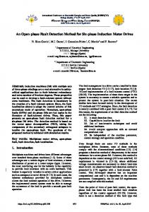
2. IN-PLANE MEMS VIBRATION MEASUREMENTS IMAGING TECHNIQUE 2.1 Experimental setup The experimental setup of the MEMS vibration characterization system is outlined in figure 1. The system is based on an original home-made stroboscope unit with incremental phase shifts. This one, is described in reference [5]. This digital timer circuitry unit generates all the control signals required to measure microstructure motion. The observed specimen is driven at a fixed frequency and illuminated by a pulsed high luminosity LED at four equallyspaced phases of the vibration. In this way, the harmonic motion is “frozen” four times per period, and can be captured using a digital CCD camera. The studied sample is harmonically excited at a constant frequency in the range from a few Hz to 200 kHz, according to the operational limits of the strobe light source response time (lower than 500 ns). The system’s spatial accuracy is governed by the image capture system optics and pixel resolution. The micro-device is observed with a standard optical microscope and imaged with a high-speed progressive scan area Dalsa CA-D1 12-bit grey-value resolution digital camera. This camera is based on a 256×256 pixels CCD sensor array. The sensor has 16 µm square pixels with 100% fill factor. Finally, frames are recorded using a Matrox Meteor II digital frame grabber and stored in a digital video sequence before image processing. These features result in a system that can acquire highly accurate images of the harmonic MEMS motion.
Fig. 1. Experimental setup
2.2 Digital lock-in After acquisition, the images sequence is stored in a microcomputer for subsequent processing. As mentioned above, processing is based on phase correlation method. The image sequence is composed of 4N images because the lock-in method needs 4 images per period for computing amplitude and phase. Moreover subtraction of the opposite phase images allows to suppress some camera defects. Therefore, because signal-to-noise ratio (SNR) of the camera signal is low (short light pulses), integration must be used in order to improve this ratio. For a recorded video sequence including N frames of the moving MEMS “frozen” by the strobe LED, we have N/4 frames at four discrete phases of the periodic motion (θ, θ+π/2, θ+π and θ+3π/2) which are then bit wise summed modulo 4 in order to obtain four average frames Sj (x,y) :
S j ( x, y ) =
4 N
N
∑I 4
n =1
j + 4 ( n −1)
( x, y ) for j=1 to 4
(1)
Where In(x, y) is the nth frame of the video sequence, (x, y) are respectively the pixel row and the pixel column, j the image index of the periodic motion selected phase. Since, the measurement displacement resolution is limited by the camera noise, the main advantage of this method is the possibility of increasing the SNR by increasing the number of summed images in the video sequence. Starting from these four resulting average images, the periodic motion of the specimen is accurately estimated by computing the value of the displacements between the first image, chosen as a reference, and the three following ones. Magnitude and phase are computed by summing the corresponding displacement values as explained below. Assuming a harmonic motion of magnitude A and pulsation ω of the vibrating object, four snapshots of the specimen are taken at four equally-spaced phases (π/2 shifts) of the stimulating frequency as described above. The successive observed positions Pj (j = 1 to 4) of the object are expressed by the following relation and presented in figure 2: Pj = A0 + A Sin( ω tj + ϕ0)
(2)
such as : ω tj =( j-1)× π/2 modulo 2π for j = 1 to 4 where (A0, ϕ0) are respectively the initial magnitude and phase and tj the snapshot time. By combining and adding the previous equation we obtain: 2 2 A = 1 (P1- P3 ) + ( P2- P4 ) 2 P -P ϕ0 = atn 3 1 P2 - P4 1 A0 = (P1 + P3 + P2 + P4 ) 4
(3) (4) (5)
Considering P1 as a reference position, we have: P1 − P3 = d11 −d13 P2 − P4 =d12 −d14 P1 + P2 + P3 + P4 =d11 + d12 +d13 + d14
(a) (b) (c)
(6)
Where d11=0, d13, d12, d14 are respectively the specimen displacements between the first image and the three following ones. We have used phase correlation motion estimation algorithm to calculate subpixel shift displacements (d1j, for j=2 to 4) between the successive pairs of images as described in the next section.
Fig. 2. Schematic diagram of both the waveform motion and the corresponding object positions
3. BASIC PRINCIPLES OF SUBPIXEL MOTION ESTIMATION Subpixel motion detection algorithms are based on changes in grey values between two pictures, which occur even for subpixel displacements (figure 3). In order to evaluate subpixel shift displacements between a pair of images without interpolation, we have chosen a phase correlation based algorithm. This one is implemented using fast Fourier transform (FFT). This method is explained below. frame n
frame n+1 dx