constant Talue of hy. = . ... of the o! ect slice with hy. = is the phase e V hp Ï ... as o!tained with a standard phase-stepping routine Vee. The unwrapped phase in ...
Phase-Shifting Common-Path Interferometer with Binary Grating: Application on Optical Tomography Cruz Meneses-Fa-ian, Gusta2o Rodriguez-7urita, 8. Arrizon ;1= Benemerita Uni2ersidad Autonoma de Pue-la, Facultad de Ciencias Fisico-Matematicas Apartado Postal 1152, Pue-la PUE H2III, MJxico. Tel.: ;N52= 222 229 55II Ext. 21I9, Fax: ;N52= 222 229 5P3P, cmenesesRfcfm.-uap.mx, gzuritaRfcfm.-uap.mx, ;1= Instituto Nacional de AstrofVsica, Wptica y ElectrYnica, Apartado Postal 51 y 21P, Pue-la PUE H2III, MJxico, Tel.: ;N52=-;222= 2PP-31II Z 2[H2I11, Ext. 1219, Fax:;N52=-;222= 2[H-29[I, arrizYnRinaoep.mx ABSTRACT An experimental setup for phase extraction of 2-D phase distri-utions is presented. The system uses a common-path interferometer consisting of two windows in the input plane and a translating grating as its pupil. In the output, interference of the fields associated with replicated windows is achie2ed -y a proper choice of the windows spacing with respect to the grating period. Because in this type of interferometer a grating is placed as a spatial filter, the phase changes which are needed for phase-shifting interferometry can -e easily performed with translations of the grating dri2en -y a linear actuator. Some experimental results as well as applications on Optical Tomography are shown.
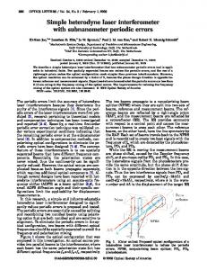
Keywords: Interferometry, Phase-shifting, Ronchi rulings, Spatial Filtering 1. INTRODUCTION It has -een recently presented a no2el Fourier theory descri-ing the image-formation process of a common-path interferometer which uses grating displacements a1b. The interferometer consists of a telecentric, [f-Fourier imaging system with two windows in the o-cect plane and a -inary ruling ;a Ronchi ruling= as a spatial filter ;see the imaging system depicted in Fig.1.a. Denoting with λ the wa2elength of the illuminating monochromatic optical radiation and with f the focal length of the transforming lenses, the sdetch is a modification of the common-path interferometer as reported earlier where only a cosine grating and a -inary phase grating were considered a1b.= In the image plane of this system, two series of diffraction orders appear ;i.e. two discrete spectra=, each series consisting of replications of each window falling apart -y distances that are multipliers of λf Z d , d -eing the grating period. On the other hand, the two spectra are mutually displaced according to the spacing xI of the windows in the o-cect plane. Then, -y proper choice of the distance -etween windows with respect to the grating period d of the ruling, a con2enient superposition of diffraction orders can -e achie2ed. Under these conditions, interference patterns centered on each diffraction order can -e o-tained due to the coincidence of the replicated fields from the windows. Fig.1.a shows superposition of orders -1 with I and I with N1 ;case of d = λf Z xI = while Fig.1.shows superposition of orders N1 with -1 ;case of d = 2λf Z xI .= Because the amplitudes of the
± 1 orders are
theoretically eeual for symmetrical grating spectra, the fringe 2isi-ility of their interference is expected to -e unity ;a-solute 2alue= in many types of gratings ;Fig.1.-=. In contrast, for the case of the superposition of non-symmetrical orders ;as in Fig.1.a=, this could -e not the case and the corresponding fringe 2isi-ility should -e less than unity in a-solute 2alue. fowe2er, this can -e of no important conseeuence for many practical applications pro2ided the resulting fringe 2isi-ility is not too low.
!th International -or.shop on Adaptive Optics for Industry and Medicine: edited by -enhan 10 I
Fig.1. Superposition -etween diffraction orders of the optical fields associated to two windows in the o-cect plane ;L, F= at two different 2alues of the distance -etween their centers, xI. a= Fulfillment of condition ;I,N1= and ;-1,I= orders. -= Fulfillment of condition
d = λf Z xI leads to the superposition -etween
d = 2λf Z xI leads to the superposition -etween ;-1,N1= orders.
In addition, the fringes of these patterns can -e easily shifted -y dri2ing the grating along its grating 2ector. These fringe shifts occur -ecause a gi2en displacement of the filter in the freeuency plane introduces a relati2e phase -etween the interfering fields in the image plane which is proportional to the filter displacement. As in our experiments, an actuator can dri2e the grating -ut the use of a lieuid crystal display for displaying shifted gratings has also -een suggested a1b. It can -e thus recognized that such a system ena-les the introduction of phase 2alues into diffraction orders as desired, there-y offering the possi-ility of shifting interference patterns as reeuired in phase-shifting interferometry a2b. Thus, this de2ice has resem-lances with well-dnown phase-shift methods using grating displacements a2, 3b, which has -een used as phase shifters in phase-shifting interferometers a3b. It is different from them, howe2er, in that it uses two displaced windows as an input. Because the proposed interferometer performs as a common-path interferometer, it seems to present some practical ad2antages as a good sta-ility. Then, com-ining this ad2antage with its relati2e easiness for introducing phase steps, it might -e worthwhile to explore its properties regarding phase-shifting interferometry. 2.
BASIC EXPERIMENTAL SET-UP
Fig.2 shows the experimental set-up, which is -asically a telecentric, dou-le Fourier -transform spatial filtering imaging system ; f = [hcm =. The o-cect O under inspection is a transparent o-cect or optical field placed cust -efore the x-y o-cect
Proc? of @PIA Vol? CDEF CDEFDXMI Downloaded From: http://spiedigitallibrary.org/ on 04/12/2013 Terms of Use: http://spiedl.org/terms
plane. The optical system can use a clean, collimated fe-Ne laser as the light source ; λ = P32.h nm =. The x-y plane comprises two rectangular windows of sides a and b with a mutual separation of xI ;Fig. 2.a=, -eing their respecti2e positions gi2en -y coordinates ;- xI Z 2 , I= and ; xI Z 2 , I= respecti2ely. One of the windows allows the light emerging from the o-cect to enter into the system, while the second window transmits light than has not tra2eled through the o-cect, thus acting as a reference. In the freeuency plane of la-oratory coordinates ; u, v =, a Ronchi ruling R with a nominal spatial freeuency of 1III lines per inch ;a corresponding period of d = 25.[ µm = and a fill factor of roughly I.5 is placed as a spatial filter with its rulings parallel to the 2ertical line. An actuator DC can dri2e horizontally the carrier which supports the Ronchi ruling. Spatial freeuencies can -e thus written as u Z λf , v Z λf .
(a)
],it
I
/
M
PIN,' ic f3
I
/OSC
I
.,. I
CCD Fig.2. Common-path experimental grating interferometer: O, o-cect samplei DC, actuator to dri2e the gratingi CCD, camera recei2ing one of two possi-le interference patternsi PC, computer control to gra- the pattern, display and processing. Michelson interferometer for cali-ration of the grating shift in dependence of the 2oltage pulse width applied to the actuator: M ;attached to the dri2er displacement=, Mj, mirrorsi BS, -eam splitteri PIN, point detector at Michelson pattern centeri OSC, oscilloscope. a= Windows geometry ;o-cect plane.= The illumination of the Michelson interferometer is independent from the one used in the grating interferometer.
A mirror M attached to the carrier is a part of one arm of a Michelson interferometer for cali-ration and monitoring of the grating displacements ;Fig.2=. The illumination of this system is in fact euite independent from the one used in the grating interferometer ;!lm 5[3.5 nm.= A PIN detector at the field center of the Michelson interferometer output deli2ers an electrical signal to an oscilloscope for fringe motion detection and characterization. A 2aria-le pulse generator was constructed to adcust -oth the 2oltage le2el and the pulse width of the pulse applied to the actuator separately. The 2oltage le2el of the pulse controls the actuator action speed while its dri2ing distance is determined -y the pulse width. At a constant 2oltage le2el, the pulse width needed to o-tain a desired interference patterns shift can -e found. Typical displacements of the mirror M in fringe num-ers as a function of the pulse width applied to the actuator employed were 2ery linear for se2eral 2oltages of the pulse ;[-9 V= within a range from 2 to 12I ms.
3. EXPERIMENTAL RESULTS AND PHASE-SHIFTING
Proc? of @PIA Vol? CDEF CDEFDXMR Downloaded From: http://spiedigitallibrary.org/ on 04/12/2013 Terms of Use: http://spiedl.org/terms
The condition depicted in Fig.1.a, namely d ≡ λf Z xI , was first experimentally o-tained ; x I = 1.2cm =. This condition was chosen in order to deep xI as small as possi-le, so as to remain within the proper space range offered -y the transforming lens aperture. The CCD-camera is aligned with one interferogram resulting from o2erlapping of orders I and N1. Fig.3 shows a seeuence of fi2e interferograms appearing while o-ser2ing Canada -alsam placed on one of the faces of a microscope slide. The slide faces normal are horizontal during the o-ser2ation, so the oil flows down. As the thicdness of the oil layer changes so the fringes modify themsel2es accordingly. Fringe 2isi-ility results good enough for data capture and 2isual o-ser2ations.
Fig.3. A seeuence of interference patterns from Canada -alsam sliding down o2er a fixed glass slice in trans-illumination
0°
90°
180°
270°
WWl Iii iu i-u
LILIIIU1IIH II'
'11flhI1111llU1 UI
I
Fiulill ii HI11I111 11111111H iI!IIIIIfl 111111
I
i1It1UEIItLP IUI!JIIIII HIIELIUu1
'1 t 1JII1lli ll1IllIUR1
Fig.[. Four interferograms with a phase shifts of 9In in -etween for two samples. a= A glass wedge. -= A folded piece of acetate foil. c= Another piece of acetate fold.
Proc? of @PIA Vol? CDEF CDEFDXMS Downloaded From: http://spiedigitallibrary.org/ on 04/12/2013 Terms of Use: http://spiedl.org/terms
It was chosen phase-shifting interferometry with shifts of 9In steps a2b. To achie2e these shifts, first a phase shift of 1hIn was found -y looding complementary interference patterns as o-tained with a proper pulse width applied on the actuator. According with experimental cur2es resulting from the Michelson interferometer, a fraction of the pulse width gi2es a fraction of 1hIn in the same direction of displacement. This linearity was used to find the desired shift of 9In. Such displacement of 1hIn amounts to -e of d Z 2 in the grating plane ;freeuency= and it is eeui2alent to introduce a shift of ; d Z 2= Z λf = 1 2 x I in the image plane a1b. To 2erify the resulting grating shift, the tra2eling distance of the mirror M dri2en -y the actuator was measured with the Michelson interferometer. It was not find contradiction in the resulting 2alues. Experimental shifted interferograms are shown in Fig.[ in arrays of horizontal rows. In the upper row ;Fig.[.a=, the four interferograms mutually shifted -y 9In phase and corresponding to a commercial glass wedge are displayed. In the middle row ;Fig.[.-=, the shifted interferograms of an acetate foil are shown, while at the lower row ;Fig.[c=, the respecti2e interferograms of another similar foil with a different -ending shape are to -e seen. Complementary contrast in interferograms pairs In-1hIn and 9In-1hIn can -e seen.
Unwrapped
Wrapped
IJJII1MThIII ________ J1
(1IIILi Ill (b)
I
rciiiiii'•iir 1
—J
Fig.5. Resulting wrapped and unwrapped phases of the pre2ious interference pattern sets shown in the Fig.[. a= From the glass wedge. -= From the folded piece of acetate foil. c= From the other piece of acetate fold.
In Fig.5, wrapped and unwrapped phases for the samples pre2iously shown in Fig.[ are plotted in gray tones in arrays of two respecti2e columns. A group of corresponding four interferograms was exported to a proper routine for wrapped phase calculation. The resulting wrapped phase image file was followed -y another routine for phase unwrapping. From left to
Proc? of @PIA Vol? CDEF CDEFDXM! Downloaded From: http://spiedigitallibrary.org/ on 04/12/2013 Terms of Use: http://spiedl.org/terms
right, the wrapped phases are first shown. Then, the unwrapped phase plots in gray le2els follow. No smoothing was employed in these results. In spite of the loss of aperture size and homogeneity in illumination, this system performs with relia-ility, as next tomographic applications suggest.
4. APPLICATION ON OPTICAL TOMOGRAPHY 4.1. EXTENDED SET-UP AND DATA ACQUISITION The descri-ed interferometer was employed for tomographic data aceuisition ;Fig.P=. An interface was designed for data capture ;not shown=. The image detected in the CCD camera is displayed in a main window to select an inspection frame, which in turn is displayed in a smaller window where the operator can select a scanning line on the field. When the scanning line is chosen, the lecture of irradiance 2alues on that particular line -egins for storage as a row of a data matrix. The scan is then displayed in a third window. When this step is finished, the stepping motor dri2es the sample to the next angle according to the prefixed step. A new scan is performed on the same scanning line and, when finished, it is staded o2er the first scan. In this way, a composite image is constructed and it would coincide with a sinogram if an o-cect with a-sorption were inspecting under parallel procection regime a[b.
t(x,y)
(a)
F(u,i')
M tf(x,y)
CCD Fig.P. Grating interferometer adapted to an Optical Tomography system. Addition of an stepping motor and a lieuid gate.
For fringe data aceuisition using the grating interferometer, points of coordinate p = x along a line are scanned at a constant 2alue of
y = h . This procedure defines an irradiance I ϕ ; p = = I I+1 ; pi h= taden at a procection angle ϕ ,
which is stored as a row of [II data ;h--it gray scale=. The o-cect is rotated for another capture and storage. When this procedure is repeated at I.9n steps to co2er the range I° ≤ ϕ ≤ 3PI° , the 2alues of I ϕ ; p = result stacded as rows
Proc? of @PIA Vol? CDEF CDEFDXMC Downloaded From: http://spiedigitallibrary.org/ on 04/12/2013 Terms of Use: http://spiedl.org/terms
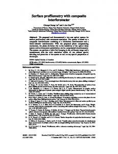
according to ϕ , finally resulting in a composite image with size of [II x [II pixels. Sometimes, howe2er, it -ecomes sufficient to employ a 1.h n step. In that case, the resulting image is managed to ha2e only 2II x 2II pixels. Experimental 1D interferograms I ϕ ; p = construct a 2-D composite interferogram o2er the plane p − ϕ , thus appearing an interferogram instead of a traditional sinogram a[b. Four such composite interferograms are shown in Fig.H ;four 2ertical arrays, a-d= for a glass sample ;microscope slide= in respecti2e horizontal arrays of four images. Each image in a horizontal array -elongs to the same sample and the same raster line, -ut there is a phase difference of 9In -etween interferograms which is induced -y shifting the Ronchi ruling as descri-ed.
Fig.H. Composite interferograms in the plane of a con2entional sinogram from procections of a microscope slide. Constructed interferograms from phase-shifted procections ;a-d= corresponding to phase shifts of In, 9In, 1hIn and 2HIn respecti2ely, e= resulting wrapped phase, f= resulting unwrapped phase, and ;g-h= two plots of the reconstructed o-cect o-tained from f=. All images are data array of [II x [II pixels. Dimensions in mm ;g=.
Composite continuous fringes are o-tained in spite of the fact that each image of the same o-cect has -een taden separately. The presence of such fringes indicates detection of phase information within the -orders of the o-cect procections. They exhi-it symmetry a-out
ϕ = 1hI !
a[b. There are also continuous fringes of low freeuency e2en in the -acdground.
4.2. SINOGRAM EXTRACTION AND RECONSTRUCTION. To o-tain a sinogram, it is assumed that the parallel procection
φ ; pi h= , which can -e extracted from I ϕ ; p=
" f ϕ ; p= of the o-cect slice a[b with y = h is the phase
-y dnown technieues. Using the phase-shifting system as descri-ed a-o2e,
the four shifts generating the interferograms shown in Fig.Ha-d were found. The induced phase step shifts the fringes of composite interferograms as a whole. For each phase-shift, a complete turn of the o-cect had to -e done, -ut the
Proc? of @PIA Vol? CDEF CDEFDXML Downloaded From: http://spiedigitallibrary.org/ on 04/12/2013 Terms of Use: http://spiedl.org/terms
reproduci-ility of the zero position of the stepping motor after a complete turn was good enough to deep the composite interferograms in proper relati2e positions. The interference fringes freeuencies change o2er a wide range. The -orders of the o-cect generate the highest freeuency fringes 2alues. In the lower horizontal array of Fig.H, the wrapped phase is first shown as o-tained with a standard phase-stepping routine ;e=. The unwrapped phase in a three-dimensional plot ;f= ;which is to -e " taden as an estimation of the sinogram fϕ ; p = = ℜ{ f ; xh , zh =} = is then su-cect to a standard filtered -acdprocection routine a[b to gi2e the o-cect slice reconstruction f ; xh , zh = , which is the undnown phase slice distri-ution at le2el h using proper coordinates xh , zh to descri-e the slice plane at
y = h . The corresponding reconstruction is shown in Fig.Hg-h ;gray tone
plot ;g= and three-dimensional plot ;h=.= This particular reconstruction is calculated with all of the procections within the range aIn, 3PInb. The interferometer performs with relia-ility, showing also great mechanical sta-ility. Other 2ariants of the system, as the use of gratings generated with lieuid crystal displays ;LCD=, the incorporation of technieues proper of electronic specdle pattern interferometry ;ESPI=, simultaneous data aceuisition of se2eral raster lines and use of orthogonal polarization states as parallel phase information channels are currently in progress.
ACKNOWLEDGEMENTS This word was partially supported from CONACyT ;grant [[H15= and 8IEP ;1[ZIZEXCZI5=. C. Meneses-Fa-ian is recipient of a scholarship from CONACyT ;13h11[= as a graduate student of the FCFM-BUAP. REFERENCES 1. 2. 3. [.
8. ArrizYn, D. Spnchez-de-la-Lla2e, Opt. Lett., 29(2), 1[1, 2II[. q. Schwider, R. Burow, K.-E. Elssner, q. Grzanna, and R. Spolaczyd, Appl. Opt., 25, 111H-1121, 19hP. K. Creith, , sPhase-measurement interferometry technieuest, in Progress in Optics BBVI, E. Wolf, eds. ELSE8IER Science Pu-lishers, pp. 3[9-393, 199h. S. R. Dean, sThe Radon transform and some of its applicationst, Wiley, New uord, 19h3.
Proc? of @PIA Vol? CDEF CDEFDXMF Downloaded From: http://spiedigitallibrary.org/ on 04/12/2013 Terms of Use: http://spiedl.org/terms