Phase-velocity measurements using prism output coupling for single- and few-mode .... modes are only slightly smaller than the prism index, the angles for the ...
106
OPTICS LETTERS / Vol. 11, No. 2 / February 1986
Phase-velocity measurements using prism output coupling for single- and few-mode optical fibers W. V. Sorin,* B. Y. Kim, and H. J. Shaw Edward L. Ginzton Laboratory,Stanford University, Stanford, California 94305 Received August 12, 1985; accepted November 14, 1985 A measurement technique based on evanescent coupling between guided fiber modes and radiation modes in a bulk medium is described. Modal phase velocities have been measured to an accuracy of better than 0.01%. Direct measurement of modal beat lengths and cutoff wavelengths are also possible. For a step-index fiber, refractive indices for the core and cladding were determined to an accuracy of 10-4; the core diameter was determined to an accuracy of 1%.
The design and development of fiber-optic devices and systems may require accurate knowledge of cer-
tain fiber parameters. Tolerances in the fiber specifications given by the manufacturer are at times not adequate. For example, the design of a periodic structure for phase-matched coupling between modes in a few-mode fiber", 2 requires precise knowledge of the
phase-velocity difference between the modes. In this Letter, a measurement technique is demonstrated that permits direct measurement of modal phase velocities in single- and few-mode fibers. Modal beat lengths and cutoff wavelengths can also be directly measured. By using the measured phase velocities, theoretical curves can be fitted, permitting
an accu-
rate determination of fiber parameters such as core
where f is the propagation constant of the guided mode. When a material whose refractive index is higher than the effective indices of the guided modes is placed on the polished region of the fiber, the modes become leaky and radiate their energy into the higherindex material. The angular direction of this radiation is well defined and is determined by the propagation constant of the guided mode and the index of the prism output coupler. By measuring the angle of the radiated light, the effective index (i.e., the phase velocity) of the guided mode can be determined. Referring to Fig. 1, the angle 0 of the radiated light can be equated to the effective index by
ne= (np2 - sin2
0)1/2,
(2)
ding. The measurement method consists of evanes-
where np is the index of the right-angle prism placed on top of the polished fiber region. To prevent air
cently coupling guided fiber modes to radiation modes
gaps, a thin layer of index-matching
whose angular directions are then measured. This technique was first demonstrated by Tien and Ulrich3 using thin-film waveguides. Similar methods have also been used with multimode fibers to excite and characterize modes near cutoff.4-7 The technique described in this Letter differs from earlier work in that the fiber cladding is polished away to obtain access to the more tightly bound lower-order modes without a significant change in propagation constants of the guided modes. Also, experimental results for mea-
placed between the fiber and the prism.
size and refractive-index
values for the core and clad-
oil (index = np) is
(0)
surement accuracies are given.
Figure 1 schematically shows the arrangement for measuring the modal phase velocities in a few-mode fiber. The measurement process uses one half of an evanescent field directional coupler.8 The coupler half is fabricated by bonding an optical fiber into a fused-quartz block and then polishing both the block and the fiber until only a few micrometers of cladding remain between the fiber core and the polished surface.
The phase velocity of a guided mode can be
characterized by a parameter called the effective index ne, This effective index can be defined as 0 = 2Wne/X,
(1)
0146-9592/86/020106-03$2.00/0
(b)
Fig. 1. Experimental arrangement used for coupling guided modes of a fiber to radiation modes. A high-index prism rests on top of a fiber whose cladding has been partially removed: (a) side view, (b) end-on view. © 1986, Optical Society of America
February 1986 / Vol. 11, No. 2 / OPTICS LETTERS
(ba
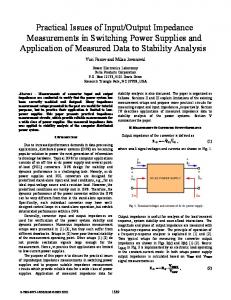
ation angles to increase to greater than 25 deg. As can be seen in Fig. 2(c), the larger radiation angle causes the radius of curvature for the radiation pattern to increase. Effective index measurements were carried out using a step-index fiber manufactured by ITT. The manufacturers specifications were a 4.4-,tm core diameter and a cutoff wavelength of 671 nm. To decrease the effect of beam diffraction, the fiber had a radius of curvature of 1.5 m in its fused-quartz block. This more than doubles the effective aperture that is achieved when the more standard radius of 25 cm is used. The prism output coupler was made of fused quartz with right-angle corners accurate to better than 1 mrad. The radiation pattern for this fiber and prism is shown in Fig. 2(a).
Cc)
107
The far-field radiation angle
leaving the prism output coupler could be measured to an accuracy of about 1 or 2 mrad. This corresponds to a measurement accuracy of about 10-4 for the effective indices of the guided modes. Although the true effective indices of the fiber are altered as the modes travel under the prism output coupler, the results from modeling this process using a four-layer slab waveguide indicate that for the amount of power radiated this perturbation should be less than the experimental measurements error of 10-4. The effective indices for the LP01 and LP11 modes of the above fiber were measured as a function of wave-
Fig. 2. Output radiation patterns projected onto a screen. (a) Pattern from a two-mode fiber. (b) Pattern from a three-mode fiber. (c) Pattern from a five-mode fiber; prism index is different from that in (a) and (b).
Figure 2 shows photographs of far-field radiation patterns for the light that leaves the prism output coupler.
In Fig. 2(a), a wavelength was used so the
fiber guided both the LP01 and the LP11 modes. The LP11 mode had the larger radiation angle since its effective index is smaller than that for the LP 01 mode. Using a different fiber, Fig. 2(b) shows the radiation
pattern when three modes are guided. The thicker
lines in Fig. 2(b), as compared with those in Fig. 2(a),
are the result of the fibers' having a shorter radius of curvature in its mounting block. This results in a smaller effective aperture in the vertical direction, which causes a spread in the radiation pattern that is due to the increased diffraction of the beam. In both
length. Since over the wavelength range of interest the material dispersion is much larger than the modal dispersion, the ratio ne/np was plotted rather than ne. This canceled out most of the effects of material dispersion. Index values np for the fused-quartz prism were calculated using a Sellmeier equation that had an accuracy of better than 10-4 over the range of interest. Figure 3 shows the measurement of ne/np as a function of wavelength. The wavelength range was covered by using an argon-ion laser and two dye lasers. Since both the prism and the fiber have similar material dispersion characteristics, Fig. 3 is essentially a plot of the modal dispersion for the fiber. A tunable dye laser allowed measurements to be taken right up to the point of cutoff for the LP11 mode. By observing the
Figs. 2(a) and 2(b) the fiber cores and the prism output
coupler were made of the same material (i.e., pure silica).
Since the, effective indices for the guided
modes are only slightly smaller than the prism index,
the angles for the radiated light were very shallow, of the order of a few degrees. Figure 2(c) shows the radiated pattern for a five-
mode fiber. Since this fiber had a doped core and a pure silica cladding all the guided modes had effective indices that were higher than the index of the fusedquartz prism. Therefore, to couple to radiation modes a higher-index prism was needed. This was achieved by using a piece of glass with an index of
about 1.52. This higher-index prism caused the radi-
>
0.998
0.997 _
450
500
550
600
650
700
M(nm)
Fig. 3. Modal-dispersion
characteristics
for a two-mode
step-index fiber. Lines are theoretical curves fitted to experimental data points.
108
OPTICS LETTERS / Vol. 11, No. 2 / February 1986
length can be measured to an accuracy of better than 10gm. This corresponds to an error of approximately 5%. The main cause of this error is believed to be
260*
250
450
500
600
550
650
700
be of interest in communication schemes since pulses
X (nm)
Fig. 4. Wavelength dependence of beat length between the LP 01 and LP 11 modes in a two-mode fiber.
Points are ex-
perimentally measured; line is theoretical.
wavelength at which the radiation pattern for the LP1 1 mode disappears, the cutoff wavelength for the fiber could be directly measured. This technique may allow for an improvement
polarization interference between the four almost degenerate eigenmodes that make up the LP11 radiation pattern. This interference can produce slight changes in the radiation angle for the LP11 mode, resulting in an incorrect value for its measured effective index. It may be possible to improve measurement accuracy by scanning the phase differences between these modes and measuring an average radiation angle. At about 540 nm the beat length reaches a minimum value, which corresponds to both the LP01 and LP11 modes' having the same group velocity. This wavelength may
in the accuracy of cutoff-
9 wavelength measurements over existing methods.
The solid lines in Fig. 3 are theoretical curves ob-
tained by solving the eigenvalue equations for a stepindex fiber. Material dispersion for the fiber was assumed to be the same as for the fused-quartz prism. The theoretical curves were fitted to the experimental points by varying the core index nj, the cladding index n2, and the core diameter d in a step-index model for
the fiber. The best-fit parameters, used for the plot-
ted curves in Fig. 3, are nj = 1.4580, n2 = 1.4536, and d = 4.56 ,m. Changes in the core or cladding index of 10-4 or in the core diameter of 0.04 gm resulted in
noticeable deviations between the theoretical curves and the experimental points. The cutoff wavelength calculated by these best-fit parameters is 674 nm. This compares favorably with the value of 672 nm measured by observing when the LP11 radiation pattern disappeared and with the 671-nm value given by the manufacturer. The above results show that for a step-index fiber, prism output coupling can be used to determine absolute core and cladding indices to an accuracy greater than 0.01%along with an accuracy of better than 1% for the core diameter. Figure 4 shows the beat length Lb between the LPo1 and LP11 modes plotted as a function of wavelength.
Both experimental points and theoretical curves use the same values as those in Fig. 3. The spread in the experimental points of Fig. 4 indicates that the beat
in each mode propagate at the same speed. In summary, a method for measuring modal phase velocities to an accuracy of 0.01%has been described. Direct measurements of cutoff wavelengths can also be performed. By matching theory to experimental results for a step-index fiber, absolute core and cladding indices have been determined to an accuracy of better than 10-4 together with a core diameter accuracy of less than 1%. Modal beat-length measurements between the LP01 and LP1 1 modes are estimated to have an accuracy of better than 5%. The above measurement technique requires obtaining access to the evanescent tails of the guided fiber modes. Although a polishing technique was used in obtaining the results reported in this Letter, other methods of cladding removal such as chemical etching may be equally effective. This research was supported by Litton Systems, Inc. * W. V. Sorin is currently with Hewlett-Packard Laboratories, Palo Alto, California 94303-0866. References 1. H. F. Taylor, J. Lightwave Technol. LT-2,617 (1984). 2. R. C. Youngquist, J. L. Brooks, and H. J. Shaw, Opt. Lett. 9,177 (1984). 3. P. K. Tien and R. Ulrich, J. Opt. Soc. Am. 60,1325 (1970).
4. W. J. Stewart, in Digest of Topical Meeting on Optical Fiber Transmission (Optical Society of America, Washington, D.C., 1975).5. W. J. Stewart, IEE Conf. Publ. (London) 132, 21 (1975). 6. J. E. Midwinter and M. H. Reeve, Opto-electronics 6,411 (1974).
7. J. E. Midwinter, Opt. Quantum Electron. 7,297 (1975). 8. R. A. Bergh, G. Kotler, and H. J. Shaw, Electron. Lett. 16, 260 (1980). 9. D. L. Franzen, J. Lightwave Technol. LT-3,128 (1985).