Phasor Measurement Units (PMUs) and Time Synchronization at European
Utilities. Roel de Vries, MSc EE. 16th of January 2013, AGH Krakow ...
Phasor Measurement Units (PMUs) and Time Synchronization at European Utilities
Roel de Vries, MSc EE 16th of January 2013, AGH Krakow
Contents • Phasor Measurement Units (PMU) • Wide Area Measurement System (WAMS) • Commercial Installations • Captured events • Time Synchronization
Phasor Measurement Units (PMUs)
Phasor Measurement Units (PMUs) History of PMUs • • • • • • •
Invented in 1988 at Virginia Tech 1st Commercial PMU in 1992 1st Synchrophasor standard: IEEE1344 (1995) Updated in 2001: IEEE1344-2001 Big boost after 2003 US blackout Standard updated in 2005: C37.118-2005 Standard again updated in 2011: • C37.118.1 – Measurement specifications • C37.118.2 – Communications specifications
Phasor Measurement Units (PMUs) What is a PMU? • Time Synchronized (GPS) measuring device: • 3 Phase Voltage • 3 Phase Current
• Reporting following information: • • • • •
Voltage Magnitude & Angle (Phasor) Current Magnitude & Angle (Phasor) Frequency (deviation from nominal in mHz) Rate-of-change of frequency (ROCOF in Hz/s) Analog user defined data (e.g. sampled control signal or transducer value) • Digital user defined data (e.g. status or flag)
Phasor Measurement Units (PMUs) PMU Classes (C37.118.1) • 2 Classes: – M Class & P Class
• Protection Class: fast response, no filtering required • Measurement Class: higher accuracy, filtering of aliased signals, slower response • User choses what class might be useful for what application
Phasor Measurement Units (PMUs) Steady-state requirements • Phasor requirements over a specific • • • • •
Frequency range Voltage magnitude range Current magnitude range Phase angle range THD range
ALL MEASUREMENTS NEED TO BE WITHIN 1% TVE (Total Vector Error)
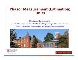
Phasor Measurement Units (PMUs) Dynamic requirements: Modulation • Phasor measurements starting at 100% rated signal magnitude and nominal frequency • Modulating according to specified signals over a certain frequency range
ALL MEASUREMENTS NEED TO BE WITHIN 3% TVE (Total Vector Error)
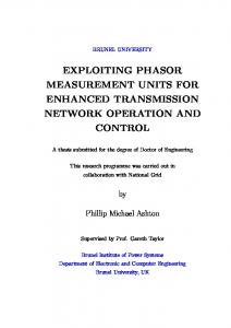
Phasor Measurement Units (PMUs) Dynamic requirements: Frequency Ramp • Phasor measurements starting at 100% rated signal magnitude and nominal frequency • Frequency ramp of 1.0 Hz/s
ALL MEASUREMENTS NEED TO BE WITHIN 1% TVE (Total Vector Error)
Phasor Measurement Units (PMUs) Dynamic requirements: Step Change • Phasor measurements starting at 100% rated signal magnitude and nominal frequency • Modulating according to specified signals over a certain frequency range
ALL MEASUREMENTS NEED TO BE WITHIN 3% TVE (Total Vector Error)
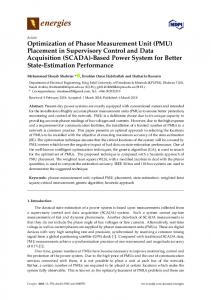
Phasor Measurement Units (PMUs) TVE Example • Measurement error steady state allowed: 1% TVE
Source: F. Steinhauser, Omicron
Wide Area Measurement System (WAMS)
Wide Area Measurement System (WAMS)
Implementation in Europe • 100+ PMUs installed and around 60 in daily operational use • First Wide Area Monitoring System (WAMS) @ SwissGrid in Laufenburg, CH (12 years ago) • Many pilot projects • Some fully operational systems • No automatic control
Wide Area Measurement System (WAMS)
Wide Area Measurement System (WAMS)
Applications • Real time data analysis • • • • •
• • • • • •
Low freq oscillation detection Phase angle difference detection Voltage stability detection Islanding detection Oscillation source detection
Post mortem analysis Re-connection after Islanding Update state estimator (dynamically) Monitor line load Automatic load balancing Prove valuable input for dynamic system model
Wide Area Measurement System (WAMS)
The Future of WAMS • IEEE and IEC working together in a Joint Synchrophasor Performance standard • Implementation of latest C37.118.1/2 standard in commercial equipment • New Applications! •
Automatic Control of grid operation?
Commercial Installations
Commercial Installations - Amprion • Year of installation: 2009 • Amount of PMUs: 11 • WAMS software: ELPROS WAProtector
– Cyclic 14 days database (full resolution, 50 frames/s) – Event database – Oscillographic database
• Applications: 1.
2. 3. 4.
Real-time analysis
a. b. c. d.
Phase angle difference monitoring Low-frequency oscillation detection Voltage instability detection Over/under value detection (Voltage/Current/Freq/Etc.)
a. b.
With other TSOs With SCADA/EMS system
Real time data exchange Power flow calculations Post-mortem analysis
Reference: Phasor Measurement Applications at Amprion Carsten Jahnke
Commercial Installations - Amprion
Reference: Phasor Measurement Applications at Amprion Carsten Jahnke
Commercial installations - elering • • •
Year of installation: 2010 Amount of PMUs: 14 WAMS software: ELPROS WAProtector
•
Applications:
– Cyclic 14 days database (full resolution, 50 frames/s) – Event database (10 000 records) – Oscillographic database
1.
2. 3. 4. 5.
Real-time analysis
a. b. c. d.
Phase angle difference monitoring Low-frequency oscillation detection Voltage instability detection Over/under value detection (Voltage/Current/Freq/Etc.)
a. b.
With other TSOs With SCADA/EMS system
Real time data exchange
Improve state estimator (development in progress) Improve system dynamical model (development in progress) Post-mortem analysis
Reference: Estonian WAMS System – Implementation and Experiences Jako Kilter, Alexei N. Goloshchapov, Bojan Mahkovec (Russian Cigre conference 2011)
Commercial installations - elering
Reference: Estonian WAMS System – Implementation and Experiences Jako Kilter, Alexei N. Goloshchapov, Bojan Mahkovec (Russian Cigre conference 2011)
Commercial installations - ELES • Year of installation: 2005 • Amount of PMUs: 20+ • WAMS software: ELPROS WAProtector
– Cyclic 14 days database (full resolution, 50 frames/s) – Event database – Oscillographic database
• Applications: 1.
2. 3. 4.
Real-time analysis
a. b. c. d.
Phase angle difference monitoring Low-frequency oscillation detection Voltage instability detection Over/under value detection (Voltage/Current/Freq/Etc.)
a. b.
With other TSOs With SCADA/EMS system
Real time data exchange
Initial test of new and refurbished generators (with Mobile PMU) Post-mortem analysis
Reference: Wide Area Measurement System in Action (PowerTech ‘07, Lausanne) T. Babnik, Member, IEEE, U. Gabrijel, B. Mahkovec, M. Perko, and G. Sitar
Commercial installations - ELES
Reference: Wide Area Measurement System in Action (PowerTech 07, Lausanne) T. Babnik, Member, IEEE, U. Gabrijel, B. Mahkovec, M. Perko, and G. Sitar
Captured Events
Captured Events – Low frequency Voltage and Frequency oscillation
Captured Events – Voltage angle difference Oscillation
Captured Events – Synching Turkish power system to ENTSO-E
Captured Events – Tie line reconnection
Time Synchronization
Time Synchronization GPS Clocks • • • • • •
GPS Clock ≠ GPS Receiver 1 input: C/A Code @ L1 freq. 1575,42 MHz Various outputs possible Internal deterministic conversion Some calculations to determine accurate time Accuracy ranging from 40ns – 1000ns typically
Time Synchronization
Time Synchronization Distribution Standards/Protocols • NTP/SNTP (Ethernet) • IEEE 1588 Precision timing protocol (PTP) (mostly Ethernet) • IRIG-B • PPS • Various ASCII serial strings
Time Synchronization Applications • • • • •
PMU Synchronization Event reconstruction Multi-Rate billing Traveling wave fault detection General IED synchronization
Time Synchronization Future Development • IEEE C37.238 available • Power profile “within” IEEE 1588v2
• IEEE 1588 will be updated • GLONASS • GALILEO • COMPASS
Thank you! Questions?
[email protected]