Eurographics Workshop on Natural Phenomena (2006) E. Galin, N. Chiba (Editors)
Physically-based Driven Tree Animations William Van Haevre†
Fabian Di Fiore‡
Frank Van Reeth§
Hasselt University Expertise Centre for Digital Media transnationale Universiteit Limburg Wetenschapspark, 2 BE-3590 Diepenbeek (Belgium)
Abstract Simulating dynamic natural wind effects on trees remains a challenging task in Computer Graphics. From an animator’s point of view it is a cumbersome and tedious task to create this effect due to the complexity of the tree shape, the numerous protruding branches and the wide variety of foliage. In this paper we present a novel method to create controllable animations of trees. Our approach borrows from several ideas from video textures, computer-assisted animation and motion graphs. It combines re-sequencing of existing material with the automatic generation of new data. Furthermore, the animator can direct the animation at each arbitrary moment using a goal based motion algorithm. First, a small set of motion data is gathered from a physically-based driven tree animation. Next, an optimised motion graph is constructed from the acquired data indicating all possible transitions from one tree pose to another. By creating in-between frames for all pairs of keyframes we ensure smooth transitions. Finally, by walking on the motion graph new non-identical animations are synthesised. The resulting animations are smooth, controllable by the animator and suitable for different production targets including 3D virtual environments (e.g., games) and 2D stylised animation. Categories and Subject Descriptors (according to ACM CCS): I.3.5 [Computational Geometry and Object Modelling]: Physically-based modelling; I.3.6 [Methodology and Techniques]: Interaction techniques; I.3.7 [ThreeDimensional Graphics and Realism]: Animation
1. Introduction Motivation. Although animation techniques like motion capturing and motion retargetting have become a very common thing in the gaming industry and in the production of feature films, they are impracticable to accurately capture
† e-mail:
[email protected] ‡ e-mail:
[email protected] § e-mail:
[email protected] c The Eurographics Association 2006.
difficult-to-model physical movement such as trees moving in the wind.
In practice, production houses of high-end feature films count with enough resources to enable dedicated programmers and animators working closely together in an elaborate process of trial and error to achieve outstanding effects [AP03]. However, this is not the case in smaller-scale productions where animators have to find their way more independently.
William Van Haevre, Fabian Di Fiore & Frank Van Reeth / Physically-based Driven Tree Animations
It is our objective to find solutions for this targetted kind of productions.
form will have a shape associated with it and this will follow the movements of the skeleton which is defined in terms of the movements of the skeletal joints.
Contribution. We present a novel method to create user controllable animations of trees. New animations are synthesised by expanding and re-sequencing existing material. Furthermore, the animator can direct the animation at each arbitrary moment in an intuitive manner.
However, for animating trees there is the issue of the control of the skeleton. It can be determined by motion capture or manual posing but this is practically impossible to do. 2.2. Video Textures
A series of results is shown in the inset. The animations are smooth, controllable by the animator (the green arrow indicates the wind force exerted by the user) and suitable for different production targets including 3D films/games (outer left image) and 2D stylised animation (outer right image). Approach. Technically the challenge is to capture, extend and re-sequence an existing animation. To this end, our approach borrows from several ideas from motion synthesis and computer-assisted animation. First, a small set of motion data is gathered from a physically-based driven tree animation. Next, an optimised motion graph is constructed from the acquired data indicating all possible transitions from one tree pose to another. By creating in-between frames for all pairs of keyframes we ensure smooth transitions. Finally, by walking on the motion graph new non-identical animations are synthesised. Paper Organisation. This paper is organised as follows. Section 2 gives an overview of related work in the field and indicates the points in common and differences with our philosophy. The data path to be followed to generate new nonidentical animations is introduced in Section 3. Then, the central stages of the data path are elaborated on throughout Section 4 to Section 6: motion gathering, motion processing and optimisation, and motion generation. Section 7 provides clarifying results. We end with our conclusions and topics for future research (Section 8).
2. Related Work In the following subsections we briefly discuss previous work in the fields related to our approach.
2.1. Computer-Assisted Animation One of the most obvious methods for generating new animations is creating in-between frames by interpolating between two or more given frames. As in our approach trees are represented as 3D geometries, we focus on skeleton-based inbetweening techniques [BW76, SR95, SGWM93]. Skeletonbased methods use an articulated skeletal structure which is normally layered to reflect the order in which the skeleton elements are encountered but may sometimes exceptionally be retained as a 3D entity and then layered on the basis of viewdependency. Each skeletal element in the view-dependent
In 2000, Shödl et al. presented a technique that allows the creation of repetitive and endless video given a short video sequence [SSSE00]. To achieve this, a sufficient number of pairs of similar frames needs to be present. This amount depends on a distance metric calculated on the image data of the individual frames. These similar frames then act as smooth transitions from which normal video playback can deviate, and thus rearrange the original frame sequence into a new synthesised video. However, when no good smooth transitions are available the creation of a video texture is impossible. More recently, similar techniques have been presented starting from bitmapped images [dJB04] as well as from vector images [VHDFVR05]. When applied to isolated movements, this technique delivers very good results. A moving tree, however, can be seen as a set of branches which move criss-cross in the wind. As a result, almost no frames would be found in which the tree poses are alike and so frames cannot be rearranged. 2.3. Motion Reuse In 2001, Mizuguchi et al. introduced move trees [MBC01] which are graph structures representing connections in a database of motion. This technique is widely used in the gaming industry as it meets the requirements of online motion generation. Unfortunately, motion trees have to be created manually which is a cumbersome task. Rose et al. presented an inverse-kinematics methodology exploiting the interpolation of example-based motions and positions [RISC01]. The key issue of their system is to allow an artist’s influence to play a major role in ensuring that the system always generates plausible results. Starting from a small number of example motions and positions, an infinite number of interpolated motions between and around these examples are generated. As this methodology is based on positioning tasks, it does not lend itself to animating trees as the target poses need to be defined manually. Recently, Kovar et al. introduced motion graphs [KGP02] to control realistic motion through a database of motion captured data. A motion graph is a constructed graph encapsulating connections among different pieces of motion. Graph walks (i.e. motion) are then simply constructed by walking on the motion graph. More recently, a similar approach was applied on image data and vector based drawings [VHDFVR05] by constructing a graph that connects c The Eurographics Association 2006.
William Van Haevre, Fabian Di Fiore & Frank Van Reeth / Physically-based Driven Tree Animations
individual keyframes by a path containing the required inbetweens that bridge them. From this data structure, graph walks are extracted in a goal based manner, resulting in interactive animations that incorporate user specified parameters. In our approach we adopt the idea of motion graphs. This will be elucidated in Section 5. 3. Overview of the Data Path Figure 1 depicts a schematic overview of the main parts of the data path. Phase I (motion gathering) performs an acquisition step to gather animation data from a small set of physically-based tree models, Phase II (motion processing and optimisation) extends this captured data into a motion graph, whereas Phase III (motion synthesis) synthesises random or interactive animations. The following paragraphs give a simplified overview of the different steps. These will be explained into detail in the following sections. PHASE I: motion gathering • • • •
create a tree skeleton create a physically-based representation exert external forces (e.g., wind) capture the trajectory of the physically-based animation
Figure 1: Schematic overview of the data path. PHASE I) Motion gathering. PHASE II) motion processing and optimisation. PHASE III) Motion synthesis.
the use of L-systems [PL90, PHHM96], applying a component based technique to describe the topology of the plant [DHL∗ 98,DL98], or actually modelling the tree structure using a professional modelling toolkit [AP03]. For research purposes we focus on the creation of tree skeletons generated using environment sensitive L-systems. These models are influenced by the availability of light and growth area and reveal realistic growth behaviour [VHDFBVR04].
PHASE II: motion processing and optimisation
4.2. Physically-based Tree Animation
• create a trivial motion path (e.g., simulating the captured animation) • construct a directed motion graph extending the captured trajectory • optimise the resulting motion graph: reduce the amount of path cycles, avoid dead ends, . . .
In this step, we attach a mass-spring system to each reference tree skeleton. A mass-spring system allows for realistically looking, physically-based tree animations and pulls the tree skeletons to their rest state when no external forces are applied to them.
PHASE III: motion synthesis • instantiate one or more new trees in the scene • attribute an optimised motion graph to each instance • render the scene according to the targetted production (3D polygon rendering, ray tracing, 2D stylised rendering, . . . ) 4. Motion Gathering
The system consists of masses attached to the tree skeleton joints. These masses are interrelated using linear and angular springs, which both restrict the motion of the individual parts in different ways. Constraints can be formulated by means of a set of behaviour functions: the linear springs minimise the length of a single branch segment to a specified rest value (Equation 1), while the angular springs constrain the angle between adjacent branch parts, thus restricting the motion of a branch to a rest angle with respect to its parent branch (Equation 2). In both equations xi j equals (xi − x j ).
The first step in the presented data path consists of data acquisition. Clinear = |xi j | − L
(1)
Cangular = xi j xk j − |xi j ||xk j | cos(α)
(2)
4.1. Tree Skeleton First of all the actual tree models that are to appear in the rendered scene need to be modelled. In the end, many instances of each reference model will be included in the final animation. Earlier research already focused on different methods that allow the creation of realistic tree models including c The Eurographics Association 2006.
Minimising Clinear is equivalent to reducing the difference between the distance from branch joint xi to x j , and their rest distance L. Cangular is defined by the definition of the inner product, based on the rest angle α within the triangle formed
William Van Haevre, Fabian Di Fiore & Frank Van Reeth / Physically-based Driven Tree Animations
by branch segments xi j and xk j . A fixed rest angle α requires the positions of the joints i, j and k to shift until Cangular is minimised. These behaviour functions are translated into force laws based on Equation 3 (we refer the interested reader to [WD01] for an in-depth explanation). The forces act on the tree joint masses and enforce the correct branch configuration when external forces are applied to the system. ˙ ∂C Fi = (−ksC − kd C) ∂xi
(3)
The parameters ks and kd correspond to the spring stiffness and damping constants. Linear spring forces carry large stiffness values and damping constants to prevent the branch segments from changing in length. The angular springs require much smaller values, depending on their position in the skeleton. When located high in the tree structure, bending occurs much more easily, and so less stiffness and damping is required.
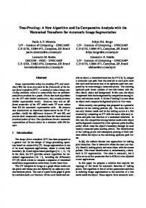
Figure 2: A tree skeleton with a mass-spring system attached to it. Linear springs are drawn in brown, angular springs in green. Left: system in its rest state. Right: wind causes the skeleton to bend towards the right side.
The weight of each mass should withstand all spring forces induced by its offspring. This implies that for each joint the weight attached to its mass should be larger than the sum of the weights of its descendants. This way, the massspring system is able to endure the complete weight of the tree. The mass-spring system’s behaviour is evaluated by means of implicit Euler steps. Each step results in a linear system of equations and is solved using the conjugate gradient method. Both techniques were implemented as explained by Baraff [BW98] and Witkin [WD01]. Figure 2 shows an example of a tree skeleton with a massspring system attached to it. This configuration is influenced by a wind force causing the skeleton to bend towards the right side. 4.3. Capturing Animation Data The final step in the data acquisition phase is to extract meaningful animation data from the previously described mass-spring system. To capture the tree motions, a user defined number of samples is taken from the branch joint positions at equal time intervals. This information is stored together with the corresponding velocities and the forces applied to them at the time of recording. For each tree skeleton, a few of these recordings can be made, containing similar or alternative tree behaviour. 5. Motion Processing and Optimisation Given the captured data, we want to reproduce meaningful motions in a computational inexpensive way. The following
Figure 3: A motion backbone is assembled from all position samples from the control point. For each pair of successive position samples (i.e. blue dots) a path segment (i.e. blue curve) is added to the backbone, by means of a short Bézier curve.
subsections describe how a motion graph can be constructed starting from a simple motion path. This graph is constructed for only one specific control point in the tree. This point will be used to guide the tree motion so it reflects the user’s intended directions. Section 6 explains how an optimal control point is chosen.
5.1. Basic Animation Path Construction Our first step in constructing the motion graph is providing the backbone from which the motion graph can be derived. This backbone consists of one motion path assembled from all position samples from the control point. For each pair of c The Eurographics Association 2006.
William Van Haevre, Fabian Di Fiore & Frank Van Reeth / Physically-based Driven Tree Animations
Consider the example shown in Figure 4. If sample pt finds a neighbour at sample si+2 , a transitional path is added. This transition is elongated by starting a few samples earlier and ending a few samples later to allow for a smoother interpolation. In this case a transitional path is added to sample pt−2 , going towards si+4 , bridging the differences of the tree skeleton between the sample positions pt−2 and si+4 . Figure 5 shows the motion backbone (indicated in blue) of Figure 3 extended with smooth transitions at each crossing (indicated in green). 5.3. Optimising Graph Paths Figure 4: When two path segments P and S cross, a transition can be created, linking the two motions that both segments represent. If sample pt has two nearest neighbours si+1 and si+2 lying forward with respect to its position, si+2 is accepted as a transitional point resulting in the creation of the smooth path segment from pt−2 to si+4 .
successive position samples a path segment is added to the backbone (see Figure 3), by means of a short Bézier curve. At this point, the resulting motion path is limited in its possibilities. It only allows for the playback of the originally captured motion and results in a dead end. For these reasons, we need to extend this backbone to a more useful graph with greater connectivity, using transitions. These transitions are short path segments connecting more distant parts of the original motion, allowing the motion generating algorithm discussed in section 6.1 to output new movements and prevent the animation from reaching a dead end. 5.2. Extending the Motion Graph Deviating from the current motion path is not as trivial as it seems. Even though the motion path crosses itself at several places within motion space, the tree pose can change drastically when ‘taking a turn’ at a crossing. To cope with these differences, a sufficiently smooth interpolation mechanism needs to be applied in order to bridge the differences in tree pose at the start and end location of the transition. 5.2.1. Motion Graph Transitions First of all transition points have to be detected in the motion path. This is achieved by applying a nearest neighbour based algorithm at each position sample while limiting the search to a distance d equal to the distance between the current sample pt and the next sample on the path pt+1 (see Figure 4). Only samples located in front of the current sample are retained. These samples lie forward with respect to the current samples velocity vector. This nearest neighbour information can be derived in a preprocessing step. c The Eurographics Association 2006.
For each sample point pt , the resulting set of nearest neighbours can be optimised further. When several neighbouring points sn are found located on the same segment S of the motion path, only those samples s that are located further in time on the original path are kept (e.g., in Figure 4 neighbour si+2 is accepted and si+1 is refused because si+1 is succeeded by si+2 , which is located further in time in the original motion path). We abandon these extra transitions because they will result in an almost identical behaviour. In its current state, there are no guarantees that the graph can produce new behaviour indefinitely. To prevent the motion graph traversal from reaching a dead end caused by the limited amount of samples that were captured, the graph needs to be updated. Traversing the backbone from the end to the start, samples can be removed when they only provide one transition (to the next sample on the path). When a sample is reached which contains an additional transition towards a sample located elsewhere in the backbone, we know the beginning of the dead end is found and all samples lying further down the path can be removed. For each sample in the motion graph, possible transitions towards this pruned segment are removed too. As a result of these optimisations, a closed directed motion graph is produced, consisting of the original transitions, smooth transitions at crossings and without dead ends. This is indicated in Figure 5 in red. If desired we can further refine this graph including removal of local cycles, restricting the amount of transitions, . . . 6. Motion Synthesis After constructing the optimised motion graph we can employ the information it represents to create alternative, physically-based driven tree animations. 6.1. Generating Motions For each tree multiple recordings of motion data can be done, all derived from the same mass-spring system. To each tree in the animated scene, first a randomly chosen instance of gathered data is assigned. Then a randomly
William Van Haevre, Fabian Di Fiore & Frank Van Reeth / Physically-based Driven Tree Animations
from the current sample position, an evaluation of all possible transitions is made. The direction that the original captured motion path would lead to after taking a transition, is estimated and compared to the user specified direction. The transition which leads the animation best towards the animators intentions is selected. This estimation can for instance be based on the velocities of a few successive samples located on the corresponding path. 7. Results
Figure 5: A closed directed motion graph. It is based on the motion backbone of Figure 3 (indicated in blue), extended with smooth transitions at each crossing (indicated in green) and contains no dead ends (indicated in red).
chosen control point is assigned. All this can be done in a preprocessing step. We empirically found that the choice for the control point (see section 5) can best be limited to the set of points located high in the tree structure as they provide the best results during the construction of the motion graph. The use of several alternative motion captures, together with the random selection of a single control point will provide different, but overall similar responses from the trees to possible user inputs. 6.1.1. Random Animations If no user interaction is required, random animations can be created for each individual tree, simply by traversing the motion graph of its control point. While interpolating between two sample positions the position of all other tree points is updated according to a similar interpolation, but applied to their own sampled data. Hence, a control point decides the trajectory for all other tree points. Each time a sample point is reached on the controlling motion path, all possible transitions leading away from this point are eligible for being chosen. Randomly choosing such a transition results in a rearrangement of the original tree movements and thus provides an overall random tree animation. 6.1.2. Interactive Animations In this section we describe a method which meets the specific intentions of an interacting animator. To this end, we extended the random method. Instead of randomly choosing a possible transition away
In Figure 6 a few snapshots are displayed from 3 animations of individual tree models. Using the realtime mass-spring solver, it took an unskilled animator (the author of this paper) less than 1 minute to provide a sufficient set of motion samples from which the resulting animations were derived. Constructing the corresponding optimised motion graph required less than 1 second and the generation of new animations was done interactively at realtime frame rates. Note that the animations generated using our system are also practicable to be rendered in a style which is extremely difficult to animate by traditional means. In this case a cartoon-like style [DFVHVR03] is applied. Figure 7 depicts two snapshots of a set of 100 tree skeletons, animated at a realtime frame rate. The green arrows indicate wind forces exerted by the user. As shown in the images, all trees correspond accordingly. Figure 8 shows two examples of possible target productions utilising our technique. The left hand side image demonstrates how our method can be employed within a virtual environment (e.g., game). On the right hand side a still from a cartoon animation is depicted. Discussion. The resulting animations correspond to the animator’s intentions. Furthermore, they display realistic behaviour as the physically-based nature of the gathered motion data is reflected upon the final animation. During the animation process, the whole state of the tree is represented by a single point. This is convenient for interpolation, but might lead to unrealistic behaviour if the set of associated states is to uncorrelated. This problem is tackled by adapting the length of each transition to the similarity of the states it bridges. All results were produced on commodity hardware. 8. Conclusions We presented a novel method to create controllable animations of trees. Based on the ideas of video textures and motion graphs combined with computer-assisted animation, our approach combines re-sequencing of existing material with the automatic generation of new data. Furthermore, the animator can direct the animation at each arbitrary moment using a goal based motion algorithm. c The Eurographics Association 2006.
William Van Haevre, Fabian Di Fiore & Frank Van Reeth / Physically-based Driven Tree Animations
First, a small set of motion data is gathered from a physically-based driven tree animation. Next, an optimised motion graph is constructed from the acquired data indicating all possible transitions from one tree pose to another. By creating in-between frames for all pairs of keyframes we ensure smooth transitions. Finally, by walking on the motion graph new non-identical animations are synthesised. Our results demonstrated that the synthesised animations are smooth, controllable by the animator and suitable for different production targets including 3D virtual environments (e.g., games) and 2D stylised animation. Future Work. In the near future we want to gather motion data by means of analysing a real input video sequence of a tree moving in the wind, and thus bypassing our physicallybased input acquisition. In the end we are striving to synthesise new animations by re-sequencing real input video, similar to the video textures technique. Furthermore we want to apply our technique to other mass-spring systems including cloth and hair simulation. Acknowledgements We gratefully express our gratitude to the European Fund for Regional Development (ERDF), the Flemish Government and the Flemish Interdisciplinary institute for Broadband Technology (IBBT), which are kindly funding part of the research reported in this paper. We also thank Tom Van Laerhoven for his contributions during the development of the mass-spring system. References [AP03] A ITKEN M., P RESTON M.: Grove: a productionoptimised foliage generator for “the lord of the rings: The two towers”. In Proceedings of the 1st International Conference on Computer Graphics and Interactive Techniques in Autralasia and Southeast Asia (GRAPHITE2003) (2003), pp. 37–38. [BW76] B URTNYK N., W EIN M.: Interactive skeleton techniques for enhancing motion dynamics in key frame animation. Communications of the ACM 19, 10 (1976), 564–569. [BW98] BARAFF D., W ITKIN A.: Large steps in cloth simulation. Computer Graphics 32, Annual Conference Series (1998), 43–54.
modeling and rendering of plant ecosystems. In Proceedings of SIGGRAPH 1998 (July 1998), ACM, ACM Press, pp. 275–286. [dJB04] DE J UAN C., B ODENHEIMER B.: Cartoon textures. In Proceedings of the 2004 ACM SIGGRAPH/Eurographics symposium on Computer animation (SCA2004) (2004), ACM Press, pp. 267–276. [DL98] D EUSSEN O., L INTERMANN B.: Software: Xfrog 2.0, http://www.greenworks.de, 1998. [KGP02] KOVAR L., G LEICHER M., P IGHIN F.: Motion graphs. In Proceedings of SIGGRAPH 2002 (2002), pp. 473–482. [MBC01] M IZUGUCHI M., B UCHANAN J., C ALVERT T.: Data driven motion transitions for interactive games. In Eurographics 2001 Short Presentations (2001). [PHHM96] P RUSINKIEWICZ P., H AMMEL M., H ANAN ˇ J., M ECH R.: L-systems: From the theory to visual models of plants. In Proceedings of the 2nd CSIRO Symposium on Computational Challenges in Life Sciences (February 1996). [PL90] P RUSINKIEWICZ P., L INDENMAYER A.: The Algoritmic Beauty of Plants. ISBN: 0387972978. Springer Verlag, 1990. [RISC01] ROSE III C. F., S LOAN P.-P. J., C OHEN M. F.: Artist-directed inverse-kinematics using radial basis function interpolation. In Proceedings of Eurographics symposium (EG2001) (2001), vol. 20(3), pp. 239–250. [SGWM93] S EDERBERG T. W., G AO P., WANG G., M U H.: 2D shape blending: an intrinsic solution to the vertex path problem. Computer Graphics 27 (1993), 15–18. [SR95] S HAPIRA M., R APPOPORT A.: Shape blending using a star-skeleton representation. IEEE Computer Graphics and Applications 15 (1995), 44–51. [SSSE00] S CHÖDL A., S ZELISKI R., S ALESIN D. H., E SSA I.: Video textures. In Proceedings of SIGGRAPH 2000 (July 2000), ACM Press, pp. 489–498. [VHDFBVR04] VAN H AEVRE W., D I F IORE F., B EKAERT P., VAN R EETH F.: A ray density estimation approach to take into account environmental illumination in plant growth simulation. In Proceedings of Spring Conference on Computer Graphics (SCCG2004) (April 2004), pp. 121–131.
[DFVHVR03] D I F IORE F., VAN H AEVRE W., VAN R EETH F.: Rendering artistic and believable trees for cartoon animation. In Proceedings of Computer Graphics International (CGI 2003) (July 2003), IEEE Computer Society, pp. 144–151.
[VHDFVR05] VAN H AEVRE W., D I F IORE F., VAN R EETH F.: Uniting cartoon textures with computer assisted animation. In Proceedings of the 3rd International Conference on Computer Graphics and Interactive Techniques in Autralasia and Southeast Asia (GRAPHITE2005) (November 2005), ACM Press, pp. 245–253.
[DHL∗ 98] D EUSSEN O., H ANRAHAN P., L INTERMANN A., M ECH R., P HARR M., P RUSINKIEWICZ P.: Realistic
[WD01] W ITKIN A., DAVID B.: Phisically based modeling. In Course Notes of SIGGRAPH 2002 (August 2001).
c The Eurographics Association 2006.
William Van Haevre, Fabian Di Fiore & Frank Van Reeth / Physically-based Driven Tree Animations
Figure 6: Several snapshots from three animations of the same tree model. A hybrid 2D/3D rendering method was applied resulting in a cartoon-like style.
Figure 7: A set of 100 tree skeletons, animated at a realtime frame rate. The animator exerted a wind force (depicted by the arrow) to the scene resulting in realtime, non identical, bending motions of each individual tree.
Figure 8: Two examples of possible target productions for our technique. Left: our method employed within a 3D virtual environment. Right: a still from a cartoon animation.
c The Eurographics Association 2006.