Dec 21, 2012 - 2INRIA Nancy, Magrit Group - Lorraine University - LORIA CNRS UMR 7503, France. Figure 1: A sequence ... scopic surgery or interventional radiology where surgeons have an ... features are first extracted from input image and training im- ..... [NMKâ06] NEALEN A., MÃLLER M., KEISER R., BOXERMAN.
Physics-based Augmented Reality for 3D Deformable Object Nazim Haouchine, J´er´emie Dequidt, Erwan Kerrien, Marie-Odile Berger, St´ephane Cotin
To cite this version: Nazim Haouchine, J´er´emie Dequidt, Erwan Kerrien, Marie-Odile Berger, St´ephane Cotin. Physics-based Augmented Reality for 3D Deformable Object. VRIPHYS - Virtual Reality Interaction and Physical Simulation, Dec 2012, Darmstadt, Germany. 2012.
HAL Id: hal-00768362 https://hal.inria.fr/hal-00768362 Submitted on 21 Dec 2012
HAL is a multi-disciplinary open access archive for the deposit and dissemination of scientific research documents, whether they are published or not. The documents may come from teaching and research institutions in France or abroad, or from public or private research centers.
L’archive ouverte pluridisciplinaire HAL, est destin´ee au d´epˆot et `a la diffusion de documents scientifiques de niveau recherche, publi´es ou non, ´emanant des ´etablissements d’enseignement et de recherche fran¸cais ou ´etrangers, des laboratoires publics ou priv´es.
Workshop on Virtual Reality Interaction and Physical Simulation VRIPHYS (2012) J. Bender, A. Kuijper, D. W. Fellner, and É. Guérin (Editors)
Physics-based Augmented Reality for 3D Deformable Object Nazim Haouchine1,2 , Jérémie Dequidt1 , Erwan Kerrien2 , Marie-Odile Berger2 and Stéphane Cotin1 1 INRIA 2 INRIA
Lille, Shacra Group - Lille 1 University - LIFL CNRS UMR 8022, France Nancy, Magrit Group - Lorraine University - LORIA CNRS UMR 7503, France
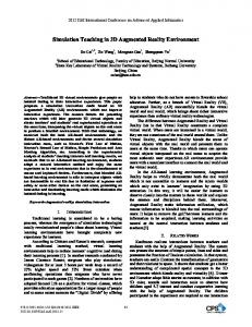
Figure 1: A sequence of images showing a cube being deformed. (Top) augmented reality images where the mesh in wireframe is superimposed on the video stream. For the deformed mechanical mesh, the surface is displayed in the middle, the volumetric mesh composed of tetrahedra is displayed at the bottom. Abstract This paper introduces an original method to perform augmented or mixed reality on deformable objects. Compared to state-of-the-art techniques, our method is able to track deformations of volumetric objects and not only surfacic objects. A flexible framework that relies on the combination of a 3D motion estimation and a physicsbased deformable model used as a regularization and interpolation step allows to perform a non-rigid and robust registration. Results are exposed, based on computer-generated datasets and video sequences of real environments in order to assess the relevance of our approach. Categories and Subject Descriptors (according to ACM CCS): H.5.1 [Information Interfaces and Presentation]: Multimedia Information Systems—Artificial, augmented, and virtual realities I.3.5 [Computer Graphics]: Computational Geometry and Object Modeling —Physically based modeling c The Eurographics Association 2012.
Haouchine N.,Dequidt J.,Kerrien E.,Berger M-O.,Cotin S. / Physics-based Augmented Reality for 3D Deformable Object
1. Introduction Augmented or Mixed Reality refers to the process of enriching or augmenting a real world environment with computergenerated data. Its applications are numerous for consumer tasks such as navigation, video games or advertising. . . but there also exists a need for augmented reality in industrial or medical contexts. Current medical procedures, for instance, favor minimally invasive surgery such as laparoscopic surgery or interventional radiology where surgeons have an indirect view of the operative field and perform the surgery through monitors using video or fluoroscopic imaging modalities. These minimally invasive surgery procedures are quite complex not only from a surgical skill standpoint but also because the visual feedback is relatively incomplete or poor. To ease the procedures, computer-generated or sensor-collected information such as tumor location, vessel, regions of interest. . . may be superimposed on the display to help the surgeons. However these information, obtained through pre-operative CT scans or MRI are mostly, for the moment, rigidly registered or even manually registered on the video streams. Such approach is not suited for deformable targets such as organs or biologic tissues for instance. This paper proposes a framework that is able to automatically track deformable objects for augmented reality purposes. The main advantage of our approach is to handle volumetric object and not to be limited to thin or surfacic objects. The originality of the paper is the combination of a 3D motion estimation to detect the surface deformation of the target and a physics-based model to interpolate the deformation over the whole model. By physics-based, we mean that the model will undergo elastic deformations and will be mechanically constrained to fit the tracked motion from stereoscopic images. It is also worth mentioning that the camera is assumed not to move over time and therefore the motion is only due to deformations. The contributions of the paper includes a flexible and modular framework to perform the tracking of deformable objects, a robust 3D motion estimator based on the combination of a feature detector and a Kalman Filter, and an original way to detect outliers and to constrain the mechanical model to follow the feature motion. Experimental validation is carried out in a synthetic environment but also in a real environment with surfacic and volumetric objects and the results exhibit the relevance of our approach. The following of the paper is organized as following. Section 2 presents the previous works related to non-rigid registration and physics-based augmented reality.Section 3 explains our approach while section 4 details the experimental results obtained on several datasets (synthetic and real).
2. Related Work In this section we present the previous work related on Augmented Reality for deformable models. First by presenting
an overview of non-rigid registration methods, second by presenting previous works on physics-based augmented reality techniques. 2.1. Non-rigid registration Non-rigid registration is still an ill-posed problem in computer vision. To solve this problem two different approaches are distinguished: Feature-based methods and Direct methods. In feature-based methods, a correspondence between image-features has to be established. Distinct points called features are first extracted from input image and training images based on their quality (i.e. their robustness to image transformations), then a matching between features is computed. These features are eventually used to estimate the surface deformations. In computer vision, a large number of features detector and matching algorithms have been proposed. For fast nonrigid surface detection, Pilet et al. [PLF08] propose a wide baseline features matching to find correspondences between a reference and a target image, combined with a 2D deformable meshes and a robust estimation technique. This approach is robust to large deformations and changes in lighting but fail in presence of self-occlusions due to the features missing in occluded region. In order to reduce the number of iteration of the previous method Zhu et al. [ZL07] used a progressive Finite Newton algorithm and an efficient factorization method to solve the optimization problem. In order to track the deformations of the heart surface using stereo endoscope images, Richa et al. [RBP10] proposed an hybrid visual tracking combining the SIFT [Low04], a modified Lucas-Kanade algorithm proposed by Steyanov et al. [SMD∗ 05] and a region-based method [RPL10]. The unreliable measurement of the tracking are interpolated with a Thin-Plate Spline used as 3D dense model. This approach suffers from limitation when the heart surface is occluded by surgeons instruments. In contrast to feature-based methods, direct methods use the entire intensity of the image instead of sparse points. In order to register non-rigid pairs of images, Bartoli and Zisserman [BZ04] used Radial Basis Mappings for learning the distortion model. The centers of the Radial Basis Mappings are estimated in a dynamic way until a stopping criterion is reached. In their approach, Gay-Belille et al. [GBBS10] consider the occluded pixels as self-occlusion area instead of outliers and constrain the deformable model. This method allows extreme occlusions but exhibits limitations to cope with changing illuminations. Recently [HdSS12], depth camera have been introduced in order to perform a registration of a 3D deformable mesh and a 3D point cloud. Similar to direct methods, optical flow constraints can be used as an alternative to features-based method. Recently, Hilsmann et al. [HSE10] proposed an approach using theses c The Eurographics Association 2012.
Haouchine N.,Dequidt J.,Kerrien E.,Berger M-O.,Cotin S. / Physics-based Augmented Reality for 3D Deformable Object
constraints regularized by a surfacic deformable mesh. This approach was extended to recover photometric parameters to stabilize the geometric tracking against illumination changes and to obtain realistic re-texturing. 2.2. Physics-based Augmented Reality In general, features-based and direct methods are combined with deformable model to interpolate poor measurement or missing features during surface estimation. In this section we will present the related work using physics model instead of geometric model. While the topic of physics-based deformable model has been widely studied in computer graphics (for more details, the reader may refer to the state-of-the-art from Nealen et al. [NMK∗ 06]), few works have been conducted to introduce physics in Augmented Reality. In medicine, Santhanam et al. [SFHL∗ 04] used elastic properties to simulate lungs deformation during inhalation. This technique was able to superimpose the lungs over a patient simulator with precomputed deformations. Salzmann et al. [SUF08] proposed to use physics-based model to estimate 3D shapes from monocular camera by learning local deformation.
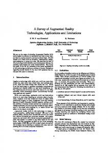
Figure 2: Computational flow of our method: The main contribution relies on the combination of the tracking and the mechanical representation.
The main contribution of this paper is to use a physicsbased model to estimate 3D deformations. While most proposed method try to learn deformations from 2D surfaces, our method uses the entire volumetric object and a prior knowledge of its mechanical properties to estimate the deformations to be superimposed into video stream. In addition to 3D estimation, the physical model is used as regulator for the unreliable measurement of the visual tracking and as motion compensation in poor textured area.
mate the deformations of the targeted object. The proposed framework can be used for non-rigid surface registration from single view and can be extended to volumetric deformations estimation from stereoscopic view. The computational flow for both single and stereoscopic view is the same, except for the three dimensional shape recovery.
3. Proposed Method This section describes our main contributions and introduces our framework to robustly and efficiently track deformable objects in order to perform augmented reality. It is worth mentioning that the described framework is modular and some components may be replaced or adapted. For instance, the 3D estimation component (see 3.1) is based on stereographic images but can handle 3D camera or other recent 3D motion estimation algorithms as Non-rigid Structure from Motion [PDBX∗ 12] or Dense Tracking And Mapping [NLD11]. The overall computational flow of our method involves two main problems which are detailed in the following subsections: first, the 3D motion estimation of the visual features; second, the computation of the model deformation and the regularization step. The figure 2 illustrates the main components of our approach as well as the data streams between components. 3.1. 3D Motion Estimation Our 3D motion estimation approach is a feature-based method. Distinct features are detected and tracked to estic The Eurographics Association 2012.
In order to estimate a three-dimensional shape from stereoscopic images, a correspondence between features detected in stereo pairs has to be established. This particular step is based on the method proposed by El Hawary et al. [EP10] who evaluate the Lucas-Kanade (LK) optical flow [LK81] and the Speeded-Up Robust Features (SURF) detector [BETVG08] for robotic-guided endoscopy and shows the robustness and the accuracy of this combination and its usability for conventional laparoscopic surgery. Since the SURF algorithm provides a descriptor, this method can easily be extended to stereo matching. The Lucas-Kanade (will be referred as LK in the rest of the paper) algorithm is an iterative optical flow that allows the detection of features in successive pairs of images under the assumptions that the local displacement in a pixel neighborhood is small. Based on the approach by El Hawary et al. [EP10], the pyramidal implementation of the LK algorithm [Bou02] is used because it is very well suited for smooth deformations. The LK algorithm is also coupled with a Kalman Filter in order to smoothen the displacement of the features. Indeed the sensitivity of the physics-based model with respect to large sudden displacements may enforce the
Haouchine N.,Dequidt J.,Kerrien E.,Berger M-O.,Cotin S. / Physics-based Augmented Reality for 3D Deformable Object
numerical stability of the model. Moreover those kind of displacements are not expected in our context. The Speeded-up Robust Features algorithm proposed by et al. [BETVG08] is both a feature detector and a feature descriptor. A descriptor is a distinct fingerprint assigned to each keypoint detected regard to its pixel properties and its response to the detector. The SURF detector is based on the determinant of the Hessian blob detector to extract distinct keypoints. The detector is robust to affine transformation, rotation and illumination changes, and is computationally fast thanks to the use of integral image. The SURF is also a robust descriptor. SURF uses the Haar wavelet response of the keypoint region to build the descriptor. The descriptors are represented as a vector of 128 dimension. Descriptors are used to find correspondences between features in pairs of images. In our case, we used the SURF descriptor for stereo matching to recover the 3D shape by computing a nearest neighbor search on descriptors vectors based on an Euclidean Distance. To filtre false matching due to repeated pattern, the epipolar constraints are applied in addition with the nearest neighbor matching. The Figure 3 shows the point cloud recovered from the stereo matching.
3.2. Physics-based Model The purpose of having a physics-based model is twofold: first, it will serve as a regularization step in order to discard outliers (i.e. false-positives features that can not be part of the tracked object) issued from the 3D motion estimation and second, it will allow to interpolate the motion and deformation of the whole volume of the object and not only the surface of the object. This second point is one of the important contributions of the paper over state-of-the-art approaches which are limited to surfacic or thin objects. There is no mechanical model that is generic enough to be suited to every deformable object and moreover each model is related to a certain number of parameters. Therefore in our framework, the component related may easily be replaced to match the specificities of the object being tracked. The only assumption made is that the model is Lagrangian (which is the case of most of the deformable models) and that can be mechanically constrained with boundary conditions. For the results detailed in section 4, an FEM model with tetrahedral co-rotational elements is used. The boundary conditions will be applied on particular 3D control points. Again, the main idea is to use the 3D motion of the features detected on the surface to guide the deformation of the whole object. These 3D control points may differ from the degrees of freedom of the mechanical model since very few assumptions are made on the model and because we want to control the number of boundary conditions that will be applied on the model in order to control the simulation time because it needs to be synchronized with the video acquisition rate. This is done by adjusting the density of the control points (fewer control points will lead to fewer constraints). These 3D control points are generated using a simple ray-casting algorithm with different patterns (either regular or random distribution). The figure 4 illustrates two types of pattern to build a set of control point according to the camera location and direction.
Figure 4: Generation of 3D control points. Density and pattern may be tweaked to build different set of control points that will constrain the mechanical model. Figure 3: 3D Estimation on a Stanford Bunny with stereo images: Top image illustrates the SURF Stereo matching were features are detected and their descriptor is used to find the correspondences between features in the images. Bottom image is the resulting sparse 3D point cloud.
To link the 3D control points of the mechanical model and the 3D features from the recovered shape, a clustering is initially computed. Each control point defines a region of interest (cluster) where the mechanical model may have influence on the deformation. The nearest features to the control point c The Eurographics Association 2012.
Haouchine N.,Dequidt J.,Kerrien E.,Berger M-O.,Cotin S. / Physics-based Augmented Reality for 3D Deformable Object
are assigned to the cluster by a combined weighted mean: a weighted mean on the Hessian responses of the SURF detector and the Shepard’s Inverse Distance Weighting (IDW). The formula used is as follow: n
D(p) =
∑ Wi di i=1
Where D is the weighted displacement of the the control point p, n the total number of neighbors and di the displacement of the feature i. Wi is the weight assigned to each feature and is as follow : wi =
i 2 ( R−h Rhi )
∑nj=1 (
R−h j 2 Rh j )
Where R is the radius of the cluster in 3D space, hi the distance of the feature from the control point and n the total number of neighbors. The Shepard’s IDW allows the nearby feature to the control point to have the largest weight and by then the largest influence in term of deformation. Combining this influence with the Hessian response allows to prevent from poor measurement during the tracking. In a large sens, this formula combine mechanical properties (radius and control point repartition) to image properties (features robustness provided by the detector). The Figure 5 illustrate the clustering phase.
from the stereo matching and unreliable features are removed. Each 3D feature which does not belong to a cluster is consider as outliers. In the Figure 5 the blue sphere represents the unreliable features. Once the clustering has been done, mechanical springs are set between features position and 3D control points in order to constraint the deformable model to match the deformation of the real object. 4. Experimental Results In this section we present the experimental result of our approach. In order to provide both qualitative and quantitative evaluation of our approach two kind of experiments are conducted: The first ones are based on synthetic data that are computer-generated in order to easily and quantitatively compare the reference deformed mesh and the one obtained with our approach. The second set of experiments is performed on real sequences where only a qualitative evaluation is available. We first present some details about the framework implementation. We then validate the clustering phase by comparing the three aforementioned weighted technique: the Hessian response, the Inverse Distance Weighting and the combination of both. We also compare the repartition of control points on the surface and compute the accuracy of each repartition. Finally, we present result for both synthetic and real sequences from single and stereoscopic view. 4.1. Implementation details and experimental set-up The feature descriptor and the Optical Flow algorithm were implemented in C++ using the OpenCV 2.4 library and the open source framework SOFA [ACF∗ 07]. For synthetic data experimentation, the stereographic images were rendered using SOFA graphics engine. The real sequences were acquired by a stereoscopic camera with a resolution of 640 × 480, a focal length of 3.7 mm and a baseline of 50 mm. The frames were acquired with a frame-rate of 30 fps. 4.2. Synthetic Data
Figure 5: Clustering phase : (Top) Image illustrates the two views of 3D point cloud estimated from stereo matching. The Blue sphere represents the outliers. (Bottom) Image is a representation of the clusters. Red sphere represent the Control Points and the Green sphere the reliable features (neighbor). By processing the clustering phase, false correspondences c The Eurographics Association 2012.
We evaluate the accuracy of the registration by calculating the Hausdorff Distance as a metric between the reference 3D mesh (that undergo a synthetic deformation) and the target 3D mesh (that undergo the deformation controlled by the tracked control points). This metric [NA02] is the reference metric for comparing two meshes in the Computer Graphics and the Reconstruction scientific community. In the following experiments, we use the RMSE (Rounded Mean Square Error) of the Hausdorff Distance as the metric. For this evaluation we use three models: A Stanford Bunny, a Human Liver and a Cube, and three types of deformations, Large, Local and Small. The Figure 6 illustrate the trained synthetic data.
Haouchine N.,Dequidt J.,Kerrien E.,Berger M-O.,Cotin S. / Physics-based Augmented Reality for 3D Deformable Object
Figure 6: The trained synthetic data : From left to right : Ears deformations of the Stanford Bunny, large, small and local Cube deformation, local Human Liver deformation in opposite direction. The volumetric mesh composed of tetrahedra is displayed in blue. The fixed constraints are represented by red markers and the direction of the force field applied is illustrated by the green lines.
4.2.1. Clustering comparative study In order to deform the 3D mesh, the displacement field of the control point has to be computed. Each control point is represented by a set of features. The influence of each feature on the displacement field of the control point is weighted by a weighted mean based on the feature quality (Hessian Response to SURF Detector) and the distance of the feature from the control point. The table below shows the results of a comparative study of the weighted techniques: Mesh Bunny Cube Liver
Def. Local Small Local Large Local1 Local2
Hessian 0.084219 0.030478 0.084395 0.083171 0.193037 0.200634
IDW 0.053334 0.033544 0.088675 0.092020 0.165178 0.211516
Combi. 0.052600 0.032852 0.076890 0.087234 0.165863 0.195849
The weighted mean based on the combination of the Hessian responses and the The Shepards’s Inverse Distance Weighting gives the best result in term of accuracy. The Shepards’s Inverse Distance Weighting gives results almost similar to this combination in some cases. However, introducing the feature quality in the Shepard’s IDW prevent the registration from poor tracking measurement. 4.2.2. Control points distribution The control points distribution has an important influence on the mesh deformation. A poor distribution of the control points reduces the accuracy of the registration. In addition, since the features are considered as outliers if they do not belong to a cluster, interesting features to track may be ignored. In this study, we make the assumption that a large number of control point increase the registration accuracy. Beside the number of control points, their distribution impacts on the registration. Thus we compare two methods of distribution, a random distribution and a regular distribution. The random distribution of the control points shows to be
Mesh Bunny Cube Liver
Deformations Local Small Local Large Local1 Local2
Random 0.052386 0.043528 0.061583 0.086755 0.133816 0.171843
Regular 0.052600 0.032852 0.076890 0.087234 0.165863 0.195849
more accurate than the regular distribution particularly when the mesh is geometrically complex but overall the two methods provides acceptable RMSE errors with the same order of magnitude. 4.2.3. Registration results The figure 7 illustrates results from our non-rigid tracking on the different synthetic data-sets that we used and several steps of the deformation (initial situation, intermediate configuration, and final configuration). From a qualitative standpoint, the results of the final configuration exhibits a good correlation between the reference mesh and the tracked one.
4.3. Augmented Reality The previous setup was also tested on real sequences. Stereoscopic view of a cube deformation and a single view of a paper shrinking. The SURF detector was able to extract 2445 features from left image and 2436 from right image. The stereo matching algorithm found 2251 correspondences based on the SURF descriptor which is more than 90%. A first filter based on the bounding box limits of the 3D mesh reduced the number of correspondences to 298. On the 131 initial control point randomly distributed on the cube surface, 83 clusters were build. The clustering reduced the number of correspondences to 105 features. During the LK Optical Flow tracking, 5 features were lost from the 105 tracked which represent c The Eurographics Association 2012.
Haouchine N.,Dequidt J.,Kerrien E.,Berger M-O.,Cotin S. / Physics-based Augmented Reality for 3D Deformable Object
Figure 8: Stereo Matching and Clustering on a real cube: Top image illustrates the Stereo detection and matching. Only matched features are shown. Bottom left image is the initial repartition of control point (Black sphere) and the resulting 3D point cloud (Blue sphere). Bottom right image illustrates the clusters. Red sphere represents the control points and Green sphere the 3D features.
Figure 7: Synthetic datasets on various meshes and deformations. The left image represents the initial condition, the middle one an intermediate motion and the rightmost one the final configuration. The reference mesh is displayed with plain faces whereas our algorithm provides deform meshes displayed in wireframe (orange lines). The results exhibit a good matching of the reference mesh and the tracked one.
less the 5%. The Figure 8 illustrates the stereo matching and the clustering result. The paper shrinking from a single view illustrated in Figure 9 shows that only four control points (one in each corner) were needed to constraint the mechanical model of the paper to shrink. The mechanical model is not directly constrained by the control point motion. Mechanical springs linked to each control point allow the motion to be smoother. The figure 1 illustrates results based on real cube deformation and the non-rigid tracking that is computed. Moreover, given the video sequence, it is remarkable that occlusions due to the tool motion are compensated by the mechanical model. 5. Conclusions In this paper we present a new physics-based method for 3D non-rigid registration. The results presented show that our tracking algorithm can track and estimate three-dimensional c The Eurographics Association 2012.
motion of various deformations. We have introduced a framework that combines 3D robust motion estimation and clustering and regularization process based on a volumetric mechanical mesh. Quantitative validation has been carried out on synthetic data and visual assessment has been performed on real video sequences. Future works will include quantitative validation on real datasets and we will try to confront our algorithm against real situations such as laparoscopic procedures. Further investigation will be conducted to estimate the robustness of our method with respect to occlusions and illumination changes. 6. Acknowledgments The authors would like to thank Pierre-Frédéric Villard, Christophe Doignon and Laurent Goffin for valuable discussions regarding this work. References [ACF∗ 07] A LLARD J., C OTIN S., FAURE F., J . B ENSOUSSAN P., P OYER F., D URIEZ C., D ELINGETTE H., B L. G.: Sofa an open source framework for medical simulation. In Medicine Meets Virtual Reality (MMVR 15) (2007). 5 [BETVG08] BAY H., E SS A., T UYTELAARS T., VAN G OOL L.: Speeded-up robust features (surf). Comput. Vis. Image Underst. 110, 3 (June 2008), 346–359. 3, 4 [Bou02] B OUGUET J. Y.: Pyramidal Implementation of the Lucas Kanade Feature Tracker: Description of the algorithm, 2002. 3 [BZ04] BARTOLI A., Z ISSERMAN A.: Direct estimation of nonrigid registration. In British Machine Vision Conference (2004). 2
Haouchine N.,Dequidt J.,Kerrien E.,Berger M-O.,Cotin S. / Physics-based Augmented Reality for 3D Deformable Object
Figure 9: Our algorithm is able to track the paper shrinking with a single camera. Top images illustrate the augmented reality images with the blue mesh superimposed on the video stream. Bottom images show from a different perspective the mesh deformation.
[EP10] E LHAWARY H., P OPOVIC A.: Robust feature tracking on the beating heart for a robotic-guided endoscope. Int J Med Robot. (Oct. 2010), 459–468. 3 [GBBS10] G AY-B ELLILE V., BARTOLI A., S AYD P.: Direct estimation of nonrigid registrations with image-based self-occlusion reasoning. IEEE Trans. Pattern Anal. Mach. Intell. 32, 1 (Jan. 2010), 87–104. 2 [HdSS12] H AYASHI T., DE S ORBIER F., S AITO H.: Texture overlay onto non-rigid surface using commodity depth camera. In VISAPP (2) (2012), SciTePress, pp. 66–71. 2 [HSE10] H ILSMANN A., S CHNEIDER D. C., E ISERT P.: Technical section: Realistic cloth augmentation in single view video under occlusions. Comput. Graph. 34, 5 (Oct. 2010), 567–574. 2 [LK81] L UCAS B. D., K ANADE T.: An iterative image registration technique with an application to stereo vision. In Proceedings of the 7th international joint conference on Artificial intelligence - Volume 2 (San Francisco, CA, USA, 1981), IJCAI’81, Morgan Kaufmann Publishers Inc., pp. 674–679. 3
[RPL10] R ICHA R., P OIGNET P., L IU C.: Three-dimensional motion tracking for beating heart surgery using a thin-plate spline deformable model. Int. J. Rob. Res. 29, 2-3 (Feb. 2010), 218–230. 2 [SFHL∗ 04] S ANTHANAM A. P., F IDOPIASTIS C. M., H AMZA L UP F. G., ROLLAND J. P., I MIELINSKA C.: Physically-based deformation of high-resolution 3d models for augmented reality based medical visualization. In MICCAI -AMI-ARCS International Workshop On Augmented Environements For Mediac Imaging And Computer-Aided Surgery 2004 (Submitted), Rennes/St.Malo France (2004). 3 [SMD∗ 05] S TOYANOV D., M YLONAS G. P., D ELIGIANNI F., DARZI A., YANG G. Z.: Soft-tissue motion tracking and structure estimation for robotic assisted mis procedures. In Proceedings of the 8th international conference on Medical image computing and computer-assisted intervention - Volume Part II (Berlin, Heidelberg, 2005), MICCAI’05, Springer-Verlag, pp. 139–146. 2
[Low04] L OWE D. G.: Distinctive image features from scaleinvariant keypoints. Int. J. Comput. Vision 60, 2 (Nov. 2004), 91–110. 2
[SUF08] S ALZMANN M., U RTASUN R., F UA P.: Local deformation models for monocular 3d shape recovery. In Computer Vision and Pattern Recognition (2008), IEEE Computer Society. 3
[NA02] N ICOLAS A SPERT D IEGO S ANTA -C RUZ T. E.: Mesh : Measuring errors between surfaces using the hausdorff distance. In IEEE International Conference in Multimedia and Expo (2002). 5
[ZL07] Z HU J., LYU M. R.: Progressive finite newton approach to real-time nonrigid surface detection. In Proc. Conf. Computer Vision and Pattern Recognition (2007). 2
[NLD11] N EWCOMBE R., L OVEGROVE S., DAVISON A.: Dtam: Dense tracking and mapping in real-time. In Proc. of the Intl. Conf. on Computer Vision (ICCV), Barcelona, Spain (2011), vol. 1. 3 [NMK∗ 06] N EALEN A., M ÜLLER M., K EISER R., B OXERMAN E., C ARLSON M.: Physically based deformable models in computer graphics. Computer Graphics Forum 25, 4 (2006), 809– 836. 3 [PDBX∗ 12] PALADINI M., D EL B UE A., X AVIER J. A ., AGAPITO L., S TOŠI C´ M., D ODIG M.: Optimal metric projections for deformable and articulated structure-from-motion. Int. J. Comput. Vision 96, 2 (Jan. 2012), 252–276. 3 [PLF08] P ILET J., L EPETIT V., F UA P.: Fast non-rigid surface detection, registration and realistic augmentation. Int. J. Comput. Vision 76, 2 (Feb. 2008), 109–122. 2 [RBP10] R ICHA R., B Ó A. P. L., P OIGNET P.: Robust 3d visual tracking for robotic-assisted cardiac interventions. In Proceedings of the 13th international conference on Medical image computing and computer-assisted intervention: Part I (Berlin, Heidelberg, 2010), MICCAI’10, Springer-Verlag, pp. 267–274. 2 c The Eurographics Association 2012.