tleneck¯ or ®cigar-like¯ pores. Filtration membranes thus obtained exhibit significantly improved flow rates without deterioration in the retention properties.
�¨¸Ó³ ¢ �— Ÿ º4[101]-2000
Particles and Nuclei, Letters No.4[101]-2000
“„Š 541.183; 539.1.074; 678.067
A NOVEL APPROACH TO PARTICLE TRACK ETCHING: SURFACTANT ENHANCED CONTROL OF PORE MORPHOLOGY P.Yu. Apel1 , S.N. Dmitriev1 , D. Root2 , V.A. Vutsadakis1 Based on the understanding of the mechanism behind a long observed but thus far unexplained effect, a new method to control the geometry of nano- and micropores is described. Surfactant molecules added to an etching solution used for etching out ion tracks, create a steric-hindrance effect which is responsible for the formation of ®bottleneck¯ or ®cigar-like¯ pores. Filtration membranes thus obtained exhibit signiˇcantly improved }ow rates without deterioration in the retention properties. New applications are made possible with these new pore geometries. The investigation has been performed at the Flerov Laboratory of Nuclear Reactions, JINR.
�µ¢Ò° ¶µ¤Ìµ¤ ± É· ¢²¥´¨Õ É·¥±µ¢ ÉÖ¦¥²ÒÌ Î ¸É¨Í: ʶ· ¢²¥´¨¥ ˵·³µ° ¶µ· ¶·¨ ¶µ³µÐ¨ ¶µ¢¥·Ì´µ¸É´µ- ±É¨¢´µ£µ ¢¥Ð¥¸É¢ 8. .�¶¥²Ó ¨ ¤·. W·¥¤²µ¦¥´ ´µ¢Ò° ¶µ¤Ìµ¤ ± ˵·³¨·µ¢ ´¨Õ ´ ´µ- ¨ ³¨±·µ¶µ·, µ¸´µ¢ ´´Ò° ´ ÔËË¥±É¥, ±µÉµ·Ò° ´ ¡²Õ¤ ²¸Ö ´¥µ¤´µ±· É´µ, ´µ ´¨±µ£¤ · ´¥¥ ´¥ ¡Ò² µ¡ÑÖ¸´¥´. „µ¡ ¢²¥´¨¥ ¶µ¢¥·Ì´µ¸É´µ- ±É¨¢´µ£µ ¢¥Ð¥¸É¢ ¢ · ¸É¢µ· ¶·¨ É· ¢²¥´¨¨ É·¥±µ¢ ÉÖ¦¥²ÒÌ ¨µ´µ¢ ¶·¨¢µ¤¨É ± ¸É¥·¨Î¥¸±µ³Ê ÔËË¥±ÉÊ, µ¡¥¸¶¥Î¨¢ ÕÐ¥³Ê ˵·³¨·µ¢ ´¨¥ ®¡ÊÉÒ²±µµ¡· §´Ò̯ ¨²¨ ®¸¨£ ·µµ¡· §´Ò̯ ¶µ·. ”¨²ÓÉ· ͨµ´´Ò¥ ³¥³¡· ´Ò, ¶µ²ÊÎ ¥³Ò¥ É ±¨³ ¸¶µ¸µ¡µ³, Ì · ±É¥·¨§ÊÕÉ¸Ö ¸ÊÐ¥¸É¢¥´´µ ¡µ²¥¥ ¢Ò¸µ±µ° ¶·µ¨§¢µ¤¨É¥²Ó´µ¸ÉÓÕ ¶·¨ ¸µÌ· ´¥´¨¨ § ¤¥·¦¨¢ ÕÐ¥° ¸¶µ¸µ¡´µ¸É¨. Œµ¤¨Ë¨± Í¨Ö Ëµ·³Ò ¶µ· µÉ±·Ò¢ ¥É ¢µ§³µ¦´µ¸É¨ ¤²Ö ´µ¢ÒÌ ¶· ±É¨Î¥¸±¨Ì ¶·¨²µ¦¥´¨°. 0 ¡µÉ ¢Ò¶µ²´¥´ ¢ ‹ ¡µ· ɵ·¨¨ Ö¤¥·´ÒÌ ·¥ ±Í¨° ¨³. ƒ...”²¥·µ¢ 4ˆŸˆ.
Chemical etching of particle tracks, also known as nuclear tracks or ion tracks, was ˇrst observed in 1958 [1]. Since 1962 [2, 3] particle tracks in solids have been the subject of intensive research. Over the years diverse applications of nuclear tracks have been developed, among which stand out the nuclear track membranes [4] and creation of microand nanostructures [5Ä8] of cylindrical or conical shapes repeating themselves in great numbers and with high uniformity. In a typical situation, an energetic heavy ion traverses a 1 Flerov
Laboratory of Nuclear Reactions, Joint Institute for Nuclear Research, 141980, Dubna, Russia Products Division, Corning Incorporated, 45 Nagog Park, Acton, MA 01720, USA
2 Science
70
Apel P.Yu. et al. A Novel Approach to Particle Track Etching:
solid leaving in its wake an ionization-damage track, which is subsequently etched away. The process of track etching and the geometry of the etched pores are mainly determined by two parameters Å the etch rate of the highly damaged track core (VT ) and the etch rate of the bulk material (VB ) which, for simplicity, is assumed to etch isotropically (Fig. 1). If VT and VB are of the same order of magnitude, the etch pit is a cone. The sharpness of the cone tip depends on the diameter dT of the damaged zone around the particle track, and is typically of a nanometer scale. If VT � VB , the etched out pore is practically of cylindrical shape. The track core is etched out very rapidly to a cylindrical channel with diameter dT . Further etching uniformly enlarges the channel at a rate of VB , while maintaining its cylindrical shape. In the present report we consider one more factor producing a dramatic effect on the evoFig. 1. Schematic model of track etching in an lution of the shape of the ion track pore in the isotropic media. The shape of the etch pit is process of chemical etching. When etching ion determined by the ratio between the etch rate tracks, various surfactants are often added to along the particle trajectory, VT , and the bulk the etching solution, with the stated intention etch rate, VB of improving the wetting of the sample. While the in}uence of small molecule surfactants is restricted to a wetting function, large molecule surfactants have a much more complex effect, which is analyzed below. First, we will consider the effect of large molecule surfactants on the bulk etch rate of a solid material in an aqueous etching solution. Large molecule surfactants are composed of a hydrophobic part, normally an alkyl chain having 8Ä12 carbon atoms, and a hydrophilic part, which is a polar moiety (ionic or nonionic). The surfactant molecules orient themselves with their hydrophobic part towards the surface of the bulk material and the hydrophilic part towards the aqueous solution. The surfactant layer which is formed is quasi-solid and partially protects the surface from the etching agent. However, the adsorbed layer does not consist entirely of surfactant molecules but also contains solvent (water) molecules. The strucFig. 2. A model for the adsorbed sur- ture of the adsorbed surfactant layer shown in Fig. 2 was factant layer (9) on a hydrophobic surproposed in [9]. Transport of water and ionic solutes face. The ˇlled (black) circles represent through the barrier formed by the surfactant is probably hydrocarbon and the open circles represent hydrophilic moieties of the surfac- similar to that through lipid bilayers [10]. The diffusion + − tant chain molecules. Squares are water of H and OH ions across such molecular layers is signiˇcantly faster than the diffusion of other ions [11]. molecules The thickness of the adsorbed layer h is of the order of the length of a fully extended surfactant molecule. For most commonly used surfactants this quantity is 2Ä4 nm. The conformation of the alkyl chains in the adsorbed layer can vary depending on the nature of the solid substrate [12]. The formation of the adsorbed layer leads
Apel P.Yu. et al. A Novel Approach to Particle Track Etching:
71
to a reduction of the etch rate (VB ) of the surface of a solid that undergoes etching. The kinetics of the process in the absence and in the presence of a surfactant is illustrated by the example of a polymer treated with alkaline solutions (see the Table). The polymer-solution interface advances 2Ä3 times faster if there is no surfactant in the etchant. The effect of the surfactant tends to decrease at higher temperatures. Transient defects in the adsorbed layer probably arise from thermal }uctuations and promote easier diffusion of water molecules and hydroxide ions to and etch products from the polymer surface. Table. Bulk etch rates of poly(ethylene terephthalate) in aqueous sodium hydroxide solutions with nonylphenyl deca(ethylene oxide) and in pure alkaline solutions
Etchant
VB Temperature
Surfactant ®slowdown¯ ratio
3 M NaOH 3 M NaOH + 0.025 % surf. 6 M NaOH 6 M NaOH + 0.025 % surf.
40◦ 1.3 mn/min 0.34 mn/min 3.4 mn/min 1.6 mn/min
3.8 2.1
VB Temperature 25 14 84 38
80◦ mn/min mn/min mn/min mn/min
Surfactant ®slowdown¯ ratio 1.8 2.2
Fig. 3. Evolution of a particle track in an etching solution with a surfactant. Successive phases of the changing geometry of the etched part of the track are presented as a, b, c, and d. Surfactant molecules are composed of hydrophilic ®heads¯ and hydrophobic ®tails¯. Etchant molecules and solvent molecules are not shown, as they are signiˇcantly smaller than the surfactant molecules
We now consider the case in which a solid material undergoing surfactant-enhanced etching contains latent (i.e., not yet etched) ion tracks. We restrict the discussion to the case of VT � VB , which in a surfactant-free etching solution would result in cylindrical pores. Diffusion of etchant molecules across the surfactant layer shown in Fig. 3a, initiates the formation of a small hole at the entrance of the ion track (Fig. 3b). When the hole attains a few nanometers in diameter, the surfactant molecules penetrate into the developing pore and cover its walls (Fig. 3c). Because initially dT ≤ 2h, further diffusion of the surfactant molecules into the growing pore is hindered. The adsorbed surfactant layer is not permeable
72
Apel P.Yu. et al. A Novel Approach to Particle Track Etching:
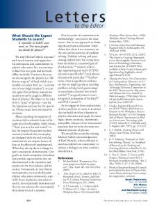
to large molecules. At this stage the transport of surfactant molecules into the pore can proceed only by lateral propagation on the pore internal wall surface. This process is slower than the diffusion in the bulk solution. Therefore, the volume inside the pore remains free of surfactant molecules for a certain time interval. However, the diffusion of hydroxide ions into the pore or etch products out of the pore, is not hindered due to their relatively small size. As a result, the inside diameter of what would be a cylindrical pore in the absence of surfactant molecules, grows at a higher etch rate than the pore entrance (Fig. 3d). After some time, ®bottleneck¯ or ®cigar-like¯ pore channels are formed. When the pore entrance diameter becomes too large for the surfactant molecules to be able to bridge the gap, the steric hindrance ceases to exist and large numbers of surfactant molecules freely diffuse into the pore and assemble on the pore walls. Starting from this moment, the etching occurs at the same (reduced) bulk rate at any point along the track axis. This phenomenon is observed with surfactants of various types. The only requirement is that the surfactant molecules be large enough to produce the described steric-hindrance effect. Experiments have shown that anionic, cationic as well as nonionic surfactants are effective. The shape of the resulting tapering of the pore, i.e., whether concave or convex, the extend of the tapering depth and also the ratio between the small and large diameters of the tapered section, depends on the etching conditions, such as etchant and surfactant concentration and temperature, and can be varied to produce the desired result. The most signiˇcant factor is the ratio of the bulk etching rate in the absence of surfactant molecules to that in their presence (the ®slowdown¯ ratio mentioned in the Table). However, in general, the pores are the more profoundly tapered the faster the etching of the bulk material. Vice versa, if bulk etching is very slow the bottleneck shape does not form because lateral diffusion provides transport of the surfactant molecules along the track simultaneously with the propagation of the etching front, resulting in a uniform bulk etching rate along the whole track length. A very small amount of surfactant is enough to produce the effect. However, when the surfactant concentration is higher than the critical micellar concentration, the mechanism is more complex. The micelles may plug the pore entrance(s) providing their own sterichindrance effect at larger pore dimensions. Experiments have shown that the effect manifests itself both in the nanometer and micrometer Fig. 4. SEM photo of the cross section of a PET scales. ˇlm sample exposed to an energetic Xe ion beam An example of a structure produced usand etched in a 6M NaOH solution containing a ing surfactant-controlled etching is presented in very small amount of an anionic large molecule Fig. 4. A sample of polyethylene terephthalate surfactant. The ˇlm thickness is 5 µm. Surface (PET) ˇlm was exposed to accelerated xenon pore density is 7 · 107 cm−2 ions which fully traversed the ˇlm. The ˇlm was subsequently etched in a NaOH solution with a very small amount of an anionic large molecule surfactant added, using standard conditions for the manufacturing of track mem-
Apel P.Yu. et al. A Novel Approach to Particle Track Etching:
73
branes. Since both sides of the ˇlm are subjected to the surfactant-controlled etching, the effect takes place simultaneously on each track end. The resulting etch track diameters on the ˇlm surface are ≤ 80 nm whereas the inside diameters are of about 450 nm. As a result, the volume porosity of the ˇlm is more than an order of magnitude higher than the surface porosity. A second example, illustrating the versatility of this method for geometry control, is shown in Fig. 5. Here ®through¯ latent tracks in a PET ˇlm are partly etched in a ˇrst surfactant-free NaOH solution so that a cone of an appropriate depth and opening angle forms at each surface of the ˇlm along the ion track. Subsequent etching in a surfactant-enhanced NaOH solution, under new conditions so as to obtain VT � VB , results in the ®bow tie¯ shape shown in the SEM photograph.
Fig. 5. SEM photo of the cross section of a PET sample exposed to an energetic Xe ion beam and partly etched in a ˇrst surfactant-free NaOH solution to obtain a small cone at each track end. Subsequent etching in a surfactant-enhanced NaOH solution, results in the ®bow tie¯ shape shown here
While the effect was ˇrst observed during etching of latent tracks, its relative simple steric (geometric) nature easily leads to predictions of its applicability to similar situations. Thus, it was predicted that already existing pores with entrances of small enough dimensions to allow a ®congestion¯ of surfactant molecules, would exhibit the same effect. Experiments were performed using surfactant-free etched nuclear track pores, very small in diameter and of perfectly cylindrical shape. The tracks were then etched in a surfactant-enhanced etching solution. The differential etching rates between the pore oriˇce and the inside of the pores resulted in the preferential enlargement of the inside pore diameter and a ®cigar-like¯ pore shape similar to that shown in Fig. 4. Similarly, the described phenomenon is expected to appear in nonaqueous polar solvent solutions with appropriate surfactants having lyophilic and lyophobic moieties, and also in the etching of nanopores other than from particle tracks and with pore oriˇces other than cylindrical. Cavities connected with the surface through very small openings and subjected to the surfactant-controlled etching should behave in a similar way, irrespective of the nature or internal geometry of the cavities. This new degree of freedom allowing the design of pore shapes, provides the most obvious beneˇts in membrane technology. Membranes containing an array of bottleneck nanocapillaries may serve as molecular ˇlters with high selectivity and high permeability,
74
Apel P.Yu. et al. A Novel Approach to Particle Track Etching:
exhibiting a much higher volume porosity than surface porosity. Apart from ˇltration, the method can ˇnd applications in cases when porous bodies with special properties are needed. Substrates with high inner porosity can be produced and used as microcontainers for encapsulation of drugs, dyes, or other chemicals, or can be used as reaction microchambers, in which one can achieve the localization of reactants in a very small volume without their immobilization. Chromatographic or catalytic substrates could be treated in a similar fashion to enhance volume porosity. Acknowledgement. The authors are grateful to O.L.Orelovitch for his help with the SEM investigations.
References 1. Young D.A. Å Nature, 1958, v.182, p.375. 2. Price P.B., Walker R.M. Å J. Appl. Phys., 1962, v.33, p.3400. 3. Fleischer R.L., Price P.B. Å Science, 1963, v.140, p.1221. 4. Fleischer R.L., Alter H.W., Furman S.C., Price P.B., Walker R.M. Å Science, 1972, v.178, p.255. Also, see Flerov G.N. Å Vestnik Academii Nauk, 1984, v.4, p.35 and Fischer B.E., Spohr R. Å Rev. Mod. Phys., 1983, v.55, p.907. 5. Martin C.R. Å Science, 1994, v.266, p.1961. 6. Blondel A., Meier J.P., Doudin B., Ansermet J.-Ph. Å Appl. Phys. Lett., 1994, v.65, p.3019. 7. Schoenenberger C. et al. Å J. Chem. Phys. B, 1997, v.101,p.497. In this paper the cigar-like shape of ion track pores, evidently etched with a surfactant, was erroneously explained. A number of other authors have observed the phenomenon, but have attributed it to a variety of factors not related to surfactants. See for example. Peterson D.D. Å Rev. Sci. Instrum., 1970, v.41, p.1252; Guillot G., Rondelez F. Å J. Appl. Phys., 1981, v.52, p.7155, and Hernandez A., Martinez-Villa F., Ibanez J.A., Arribas J.I., Tejerina A.F. Å Sep. Sci. Technol., 1986, v.21, p.665. 8. Jirage K.B., Hulteen J.C., Martin C.R. Å Science, 1997, v.278, p.655. 9. Kronberg B., Stenius P. Å J. Coll. Interface Sci., 1984, v.102, p.410. 10. Deamer D.W., Bramhall J. Å Chem. Phys. Lipids, 1986, v.40, p.167. 11. Biegel C.M., Gould J.M. Å Biochemistry, 1981, v.20, p.3474. 12. Gilchrist V.A., Lu J.R., Staples E., Garrett P., Penfold J. Å Langmuir, 1999, v.15, p.250.
Received on July 24, 2000.