Such picking algorithms have been widely used for selecting objects under a 2D
mouse cursor. ... A 3D snapping algorithm on the basis of differential geometry ...
Picking and Snapping for 3D Input Devices W U , S HIN - T ING , M ARCEL A BRANTES , DANIEL T OST, AND H ARLEN C OSTA BATAGELO Image Computing Group (GCI) Department of Industrial Automation and Computer Engineering (DCA) School of Electrical and Computer Engineering (FEEC) State University of Campinas (Unicamp) P.O.Box 6101, 13083-970 - Campinas, SP, Brazil ting,tost,ra003168,harlen � @dca.fee.unicamp.br Abstract. A picking mechanism (pointing and indicating) with the cursor is essential for any direct-manipulation application. The windowing systems, under which control a direct-manipulation application runs, provide facilities that together with special utility routines allow identifying which object within the region the user is pointing at. Such picking algorithms have been widely used for selecting objects under a 2D mouse cursor. In this paper, we present a simple yet effective application-independent 3D picking algorithm for 3D input devices. We also discuss a differential geometry based surface constraint that can be applied to the 3D cursor position for improving points matching. In order to demonstrate the techniques, two sample applications using a 3D input device are shown.
1
Introduction
In almost all direct-manipulation graphics systems an interaction task, such as scaling and rotating an object, is built on top of two basic interactions: selecting and dragging with a pointing device. Moreover, almost universally acceptable interaction syntax in a windowing system is selecting an object by clicking on it with a mouse and dragging the object by moving the mouse in a 2D space while the button is down. Besides mouses, there is a variety of complementary interaction devices such as joystick, trackballs and spaceballs for improving the control on the movement of an object. For example, the joystick is often used to move an object selected by a mouse. The decreasing cost of input devices and the increasing computer power lead to continuing improvement in interaction devices both in precision and in dimension in which the device works. There are a variety of 3D interaction devices that provide 3D position and orientation. Among them we may mention the spaceball1 that allows accurate fine positioning in 3D-space. Even though, the usually recommended procedure for manipulating an object with a spaceball is to pick it with a mouse and then drag or rotate it with the spaceball. This motivates us to look for applicationindependent 3D positioning and picking mechanisms with which we may perform the two basic interactions with the same input device also in 3D space so as already it is done in 2D space. Differently from the concept of 3D cursor given by Foley et al. [4] which is controlled by a 2D cursor, Mesquita [6] defined a 3D cursor as an extension of a 2D cursor. The 2D 1 http://3dconnexion.com/products/5000/
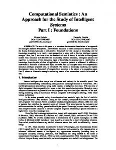
cursor is the visible representation on the screen of the 2D pointing device’s position. Because the cursor must frequently have a resolution of a single pixel, it is of common practice designating one single pixel of a cursor as the hotspot. In an analogous way, a 3D cursor is the visible representation on the screen of the 3D pointing device’s position and its unprojected shape in 3D always has a single hotspot voxel (volume element). Furthermore, Mesquita [6] developed an algorithm for emulating 3D positioning functionality for 2D input devices. Two movement modes are defined on the basis of the functions developed by Navarro et al. [3]: one is on the ��� -plane and the other is on the ��� -plane in the viewing volume (Figure 1). The user can switch from one mode to another by simply pressing or releasing the middle mouse button. The method may appear restrictive once the user is working in two dimensions at a time. However, experiments with different users let us conclude that most users can quickly adapt to the syntax of the context switching and feel that the emulated pointing device moves freely in 3D.
3D Cursor
xye
lan
pla
ne
z-p
x
Pro
jec
tion
Center of Projection
Pla
ne
Figure 1: Emulation of 3D pointing devices.
In this paper our focus is on the 3D picking mechanism surface determination. In this case, the depth value of each for input devices capable of providing an absolute or relapoint in the viewing volume is always passed to the graphtive position in 3D space. In other words, given a position ics hardware. Therefore, gathering and sorting � -coordinate in 3D we would like to determine which object is at that povalues along an eye-ray for defining the intersection intersition without resorting to application-dependent functionvals can be carried out without resorting to the application. alities. A 3D snapping algorithm on the basis of differential geometry of the manipulated surface is also devised for a user to position a pointing device more accurately in 3D. An implementation with OpenGL selection and pick com� ��
mands is presented and the experiments were carried out with use of the emulated 3D pointing device and the PSfrag space- replacements � � ��� ball 3003. Pro In the next section our application-independent 3D pickjec tion Pla ne ing algorithms are presented. Next, we discuss how we can Center of Projection control its movement constrained to a surface of interest in 3D. Then in Section 4, we show how they can be efficiently implemented with use of OpenGL. In Section 5, Figure 3: Point-in-segment test approach. results of application of these algorithms to a 3D pointing device, more precisely the spaceball 3003, are given. We If a scene only contains convex objects, the point-incould successfully determine which object it points at in segment test can be performed more efficiently by graph3D and program an imaginary gravity field around each exics hardware that is capable of returning the minimum and isting surface for constraining its movement. Finally, some maximum � values of all vertices that intersected the eyeconcluding remarks are drawn. ray. In this case, we can determine whether an object is 2
3D picking
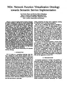
A 3D picking problem can be reduced to a problem of determining the object that intersects at a given point the eye-ray fired from the center of projection through the pixel’s center into the unprojected scene. In principle, this problem can be solved by determining all the objects that intersect the ray and performing point-in-solid inclusion tests to find out which object contains the specified 3D point (Figure 2). This approach is application-dependent, once it requires the application-dependent point inclusion test algorithms.
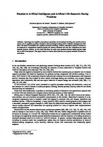
picked by drawing it and comparing the returned � values with the depth value of the 3D cursor. Figure 4 pictures the front and back faces of the cone and the sphere that intersect the eye-ray on which the 3D cursor lies. The depth value of the 3D cursor neither lies in the � -interval of the cone nor in the � -interval of the sphere. Therefore, the 3D cursor is outside of both objects.
Pro
jec
Hotspot of 3D Cursor
tion
Pla
ne
Figure 4: Improved point-in-segment test approach. Pro
jec
tion
Center of Projection
Pla
ne
Figure 2: Point-in-solid test approach. As an alternative, one may reduce the problem to a one-dimensional problem by determining the intersection intervals along the eye-ray for each object. Then, the object that is pointed at can be obtained with a point-in-segment inclusion test (Figure 3). This approach is computationally attractive when � -buffer algorithm is applied for visible-
For concave polyhedra, the point-in-segment test can also be performed by graphics hardware. In special, a hardware stencil buffer may be used to store the parity counting of objects’ faces and thus determining whether a given point is inside the object on the basis of the fact that if an eye is outside of an object of interest and an eye-ray intersects the object, this eye-ray always intersects an even number of points. In this case, we can issue drawing commands to a graphics hardware for drawing only the faces of the object of interest that appear at the pixel under the cursor before
(or after) the position of the 3D cursor and inverting the the problem is reduced to the computation of the nearest stencil buffer at this pixel. The cursor is outside the obpoint on the shape, most of which require potentially timeject if and only if the number of inversions is even, i.e., the consuming point-and-shape or the ray-and-shape intersecstencil buffer at the pixel under the cursor should remain tion algorithms. unchanged. Once the algorithm is applied on each object at In this section we present a novel procedure for snaptime, for the sake of clarity, only the state of stencil refering ping to a smooth convex closed surface � on the basis of a torus is shown in Figure 5. It induces five discrete intertwo local geometry properties at each point � : the normal vals for stencil buffer: 1 ( � � ), 2 ( � � ), 3 ( � ), 4 ( � ), and 5 vector � � and a vector � � on the tangent plane of the surface ( � � ) along the picking ray. As only the faces before the curat � . The existence of a “tangent plane” at all points of � is guaranteed because of the smoothness condition. With sor are drawn in the stencil buffer, the stencil buffer value � � and � � , we define a snapping reference coordinate (SRC) of the pixel in consideration is even, the 3D cursor is outsystem at each point � , � �"!$#%�'& , using � � and � � and conside the object. Again, the procedure explores the graphics sider that the 3D cursor locally “snaps” to this plane called hardware capabilities. snap plane. That is, its motion is restricted to this plane in Actually, stenciling is not a essential part of this althe neighborhood of � (Figure 6) gorithm. Since this method performs only parity checking using operations of inversion and does not use stencil com-* parison functions, this feature may be emulated with any buffer that can be used to count pixel overdraw, such as an PSfrag replacements +* ( , * snap plane accumulation buffer (by accumulating the overlapping fragments) or color buffer via alpha-blending (by using additive ) blending of fragments).
Hotspot of 3D cursor
ck
Ba
PSfrag replacements
��� ���
t
on
Fr
Figure 6: Snapping reference coordinate system.
���
���
��� Pro
jec
tion
The next point on � to be reached by the 3D cursor from �/. in the world coordinate (WC) system is computed as follows (Figure 7):
Pixel of Stencil Buffer
Pla
ne
Figure 5: Point-in-segment test for concave objects. 3
3D snapping
�
� .
��
��
� 3 1 053 1 � & #21 4 0 � snap plane � .
� ��
In most cases, to place a 3D cursor exactly on the object �� 0 � snap plane / � . Motion constrained of interest or to constraint its movement precisely on the to arbitrary surface surface of an object are essential for accurate interactions � with shapes. For example, if we want to trim a surface, replacements then we want the 3D cursor to be on the surfacePSfrag as we are moving it for defining a trimming curve. A technique that �� can help these tasks is snapping, which can round the actual position of the pointing device to some more appropriate �� 0 snap plane � . �/. � position. The simplest snapping technique is grid-snapping, also �6.87 � � � known as vertical or horizontal alignments. In this case, the snapping problem is reduced to a simple rounding of the device position to a point of a specified grid. There is, Figure 7: Snapped motion. however, a number of snapping to an arbitrary shape problems that cannot be reduced to vertical or horizontal alignments. To our knowledge, for handling an arbitrary shape, 1. change the reference system of � . to the � �"!$#%� . &
system; 2. the displacement #91 �43 1 053 1 � & of the 3D cursor is rounded to #91 �:3 1 0�3= ; & and added to the coordinates of �6.:?@# ;A3B;>3