Dublin Institute of Technology
ARROW@DIT Conference papers
School of Electrical Engineering Systems
2000-01-01
A summary of PI and PID controller tuning rules for processes with time delay. Part 2: PID controller tuning rules Aidan O'Dwyer Dublin Institute of Technology,
[email protected]
Follow this and additional works at: http://arrow.dit.ie/engscheleart Part of the Controls and Control Theory Commons Recommended Citation O'Dwyer, Aidan : A summary of PI and PID controller tuning rules for processes with time delay. Part 2: PID controller tuning rules. Proceedings of PID ’00: IFAC Workshop on Digital Control, pp. 242-247, Terrassa, Spain, April 4-7, 2000.
This Conference Paper is brought to you for free and open access by the School of Electrical Engineering Systems at ARROW@DIT. It has been accepted for inclusion in Conference papers by an authorized administrator of ARROW@DIT. For more information, please contact
[email protected],
[email protected].
This work is licensed under a Creative Commons AttributionNoncommercial-Share Alike 3.0 License
Preprints of Proceedings of PID ’00: IFAC Workshop on Digital Control, Terrassa, Spain, April 4-7, 2000, pp. 242-247.
A SUMMARY OF PI AND PID CONTROLLER TUNING RULES FOR PROCESSES WITH TIME DELAY. PART 2: PID CONTROLLER TUNING RULES.
Aidan O’Dwyer
School of Control Systems and Electrical Engineering, Dublin Institute of Technology, Kevin St., Dublin 8, Ireland.
Abstract: The ability of proportional integral (PI) and proportional integral derivative (PID) controllers to compensate many practical industrial processes has led to their wide acceptance in industrial applications. The requirement to choose either two or three controller parameters is perhaps most easily done using tuning rules. A summary of tuning rules for the PID control of single input, single output (SISO) processes with time delay is provided in this paper. Copyright ©2000 IFAC Keywords: PID controllers, rules, time delay.
1. INTRODUCTION This paper summarises some of the most directly applicable tuning rules for PID controllers that have been developed to compensate SISO processes with time delay, modeled in either first order lag plus delay (FOLPD) form or integral plus delay (IPD) form. It is a companion paper to that of O’Dwyer (2000a) and the two papers have similar structure. A comprehensive summary of PID controller tuning rules for processes with time delay is available from the author (O’Dwyer, 2000b). The ideal continuous time domain PID controller for a SISO process is expressed in the Laplace domain as follows: 1 G c (s) = Kc (1 + + Td s) (1) Ts i with K c = proportional gain, Ti = integral time and Td = derivative time. Many tuning rules have been defined for this PID structure. Tuning rules have also been defined for a range of alternative PID controller structures. One example of such structure is the ‘classical’ form of the PID controller: ⎛ 1 ⎞ ⎛ 1 + Td s ⎞ G c (s) = K c ⎜ 1 + ⎟ ⎟⎜ Ti s ⎠ ⎝ 1 + Td s N ⎠ ⎝
(2)
Tuning rules for these and other such PID controller structures are explicitly indicated; in all cases, numerical data is quoted to a maximum of two places of decimals. Most authors recommend application of the tuning rules for a range of model time delay to time constant ( τ m Tm ) between 0.1 and 1.0; this data, together with other relevant comments, is provided by O’Dwyer (2000b). Results from the analytical calculation of robustness criteria associated with a number of tuning rules, for a range of τ m Tm values, are presented in Section 4. A list of symbols and abbreviations used in the paper is provided in the appendix. K m e − sτ MODEL 1 + sTm m
2.
PID TUNING RULES –
Rule
Kc
Ti
Td
1 Ideal controller – G c (s) = K c (1 + + Td s) Ts i
Ziegler and Nichols (1942)
Process reaction aTm 2τ m Kmτ m a = [1.2,2]
0.5τ m
Preprints of Proceedings of PID ’00: IFAC Workshop on Digital Control, Terrassa, Spain, April 4-7, 2000, pp. 242-247. Rule
Kc
Astrom and Hagglund (1995) Chien et al. (1952) –regulator – 0% o.s.
0.94Tm Kmτ m
Chien et al. (1952) – regulator – 20% o.s.
1.2Tm Kmτ m
Chien et al. (1952) – servo – 0% o.s.
0.6Tm Kmτ m
Chien et al. (1952) – servo – 20% o.s. Cohen and Coon (1953)
Kc
0.42 τ m
2τ m
0.5τ m
Tm
0.47τ m
1.36Tm
(1)
Ti
(1)
Td
(1)
Regulator Murrill (1967) – min. IAE Murrill (1967) – min. ISE Zhuang and Atherton 2 (1993) – min. ISE
144 . ⎛ Tm ⎞ ⎜ ⎟ Km ⎝ τm ⎠
0.92
150 . ⎛ Tm ⎞ ⎜ ⎟ Km ⎝ τm ⎠
0.95
147 . ⎛ Tm ⎞ ⎜ ⎟ Km ⎝ τm ⎠
Murrill (1967) – min. ITAE Zhuang and Atherton 2 (1993) – min. ISTSE
1
K c (1)
=
Tm ⎛ Tm ⎞ ⎜ ⎟ 0.88 ⎝ τ m ⎠
0.75
⎛τ ⎞ 0.48Tm ⎜ m ⎟ ⎝ Tm ⎠
1.14
Tm ⎛ Tm ⎞ ⎜ ⎟ 110 . ⎝ τm ⎠
0.77
⎛τ ⎞ 0.56Tm ⎜ m ⎟ ⎝ Tm ⎠
1.01
0.97
Tm ⎛ Tm ⎞ ⎜ ⎟ 112 . ⎝ τm ⎠
0.75
⎛τ ⎞ 0.55Tm ⎜ m ⎟ ⎝ Tm ⎠
0.95
152 . ⎛ Tm ⎞ ⎜ ⎟ Km ⎝ τm ⎠
0.74
Tm ⎛ Tm ⎞ ⎜ ⎟ 113 . ⎝ τm ⎠
0.64
⎛τ ⎞ 0.55Tm ⎜ m ⎟ ⎝ Tm ⎠
0.85
136 . ⎛ Tm ⎞ ⎜ ⎟ Km ⎝ τm ⎠
0.95
Tm ⎛ Tm ⎞ ⎜ ⎟ 0.84 ⎝ τ m ⎠
0.74
⎛τ ⎞ 0.38Tm ⎜ m ⎟ ⎝ Tm ⎠
1.00
147 . ⎛ Tm ⎞ ⎜ ⎟ Km ⎝ τm ⎠
0.97
Tm ⎛ Tm ⎞ ⎜ ⎟ 0.94 ⎝ τ m ⎠
0.73
⎛τ ⎞ 0.44Tm ⎜ m ⎟ ⎝ Tm ⎠
0.94
⎛ Tm ⎞ ⎜ ⎟ ⎝ τm ⎠
0.73
Tm ⎛ Tm ⎞ ⎜ ⎟ 0.96 ⎝ τ m ⎠
0.60
⎛τ ⎞ 0.44Tm ⎜ m ⎟ ⎝ Tm ⎠
0.85
152 . Km
⎛ ⎜ 2.5 τ m + 0.46⎛⎜ τ m ⎞⎟ ⎜ Tm ⎞ ⎝ Tm ⎠ Tm 1 ⎛ . + 0.25⎟ , Ti (1) = Tm ⎜ ⎜135 τm Km ⎝ τm ⎜ ⎠ 1 + 0.61 ⎜⎜ Tm ⎝
Td (1) = 0.37 τ m (1 + 0.2[ τ m Tm ]) 2
For 01 . ≤
Td
Ti
153 . ⎛ Tm ⎞ ⎜ ⎟ Km ⎝ τm ⎠ 159 . ⎛ Tm ⎞ ⎜ ⎟ Km ⎝ τm ⎠
0.71
Rovira et al. (1969) – min. IAE Zhuang and Atherton 2 (1993) – min. ISE
109 . ⎛ Tm ⎞ ⎜ ⎟ Km ⎝ τm ⎠
0.87
105 . ⎛ Tm ⎞ ⎜ ⎟ Km ⎝ τm ⎠
0.90
115 . ⎛ Tm ⎞ ⎜ ⎟ Km ⎝ τm ⎠
0.57
Rovira et al. (1969) – min. ITAE Zhuang and Atherton 2 (1969) – min. ISTSE
0.97 ⎛ Tm ⎞ ⎜ ⎟ Km ⎝ τm ⎠
0.85
104 . ⎛ Tm ⎞ ⎜ ⎟ Km ⎝ τm ⎠
0.90
114 . ⎛ Tm ⎞ ⎜ ⎟ Km ⎝ τm ⎠
0.58
0.97 ⎛ Tm ⎞ ⎜ ⎟ Km ⎝ τm ⎠
0.90
106 . ⎛ Tm ⎞ ⎜ ⎟ Km ⎝ τm ⎠
0.58
Tm ⎛ Tm ⎞ ⎜ ⎟ 0.97 ⎝ τ m ⎠
0.75
⎛τ ⎞ 0.41Tm ⎜ m ⎟ ⎝ Tm ⎠
0.93
Tm ⎛ Tm ⎞ ⎜ ⎟ 0.96 ⎝ τ m ⎠
0.60
⎛τ ⎞ 0.41Tm ⎜ m ⎟ ⎝ Tm ⎠
0.85
Tm
⎛τ ⎞ 0.35Tm ⎜ m ⎟ ⎝ Tm ⎠
0.91
Tm
⎛τ ⎞ 0.49Tm ⎜ m ⎟ ⎝ Tm ⎠
0.89
Tm
⎛τ ⎞ 0.49Tm ⎜ m ⎟ ⎝ Tm ⎠
0.71
Tm
⎛τ ⎞ 0.31Tm ⎜ m ⎟ ⎝ Tm ⎠
0.93
Tm
⎛τ ⎞ 0.39Tm ⎜ m ⎟ ⎝ Tm ⎠
0.91
Tm
⎛τ ⎞ 0.38Tm ⎜ m ⎟ ⎝ Tm ⎠
0.84
⎛τ ⎞ 0.32Tm ⎜ m ⎟ ⎝ Tm ⎠
0.89
⎛τ ⎞ 0.32Tm ⎜ m ⎟ ⎝ Tm ⎠
0.83
Servo
0.95Tm Kmτm 1
0.42τ m
2.38τ m
Kc 0.96
Zhuang and Atherton 2 (1993) – min. ISTES
0.5τ m
2τ m
0.95Tm Kmτm
Rule
Td
Ti
τm τ ≤ 1 and 11 . ≤ m ≤ 2 , respectively Tm Tm
2
⎞ ⎟ ⎟ ⎟ ⎟ ⎟⎟ ⎠
Zhuang and Atherton 2 (1969) – min. ISTES
τm 0.74 − 013 . Tm
τ 120 . − 0.37 m Tm
105 . − 0.22
τm Tm
τm 0.80 − 015 . Tm
τ 0.99 − 0.24 m Tm 0.92 − 017 .
Tm 0.98 − 0.25
τm Tm
τm Tm
Tm
τm 0.89 − 017 . Tm
Direct synthesis Smith and Corripio (1985) – regulator Smith and Corripio (1985) – servo Smith and Corripio (1985) – servo – 5% o.s. Abbas (1997)
Tm Kmτm
Tm
0.5τ m
5Tm 6K m τ m
Tm
0.5τ m
Tm 2K m τ m
Tm
0.5τ m
K c ( 2) 3
Tm + 0.5τ m
Tm τ m 2 Tm + τ m
−1.00
⎛τ ⎞ 018 . + 0.35⎜ m ⎟ ⎝ Tm ⎠ 3 K c (2) = , K m (0.53 − 0.36V 0.71 ) 0 ≤ V ≤ 0.2 , V = overshoot
Preprints of Proceedings of PID ’00: IFAC Workshop on Digital Control, Terrassa, Spain, April 4-7, 2000, pp. 242-247.
Rule
Kc
Fruehauf et al. (1993)
5Tm 9τ m K m
5τ m
≤ 0.5τ m
Tm 2τ m K m
Tm
≤ 0.5τ m
min. ITAE Rule
Td
Ti
Robust
Zhuang and Atherton (1993) – min. ISTSE
Ultimate cycle 0.05Tu 0.51K u (3.30K K + 1) m
u
Tsang and Rad (1995) Tsang et al. (1993)
013 . Tu
servo 4
K c ( 3)
Process reaction 15 . τm 0.83Tm Kmτm
Witt and Waggoner (1990)
τm aTm , Kmτ m a = [0.6,1] Regulator
Kaya and Scheib (1988) – min. IAE Kaya and Scheib (1988) – min. IAE Kaya and Scheib (1988) – min. ITAE
0.98 ⎛ Tm ⎞ ⎜ ⎟ Km ⎝ τm ⎠
0.76
112 . ⎛ Tm ⎞ ⎜ ⎟ Km ⎝ τm ⎠
0.90
0.78 ⎛ Tm ⎞ ⎜ ⎟ Km ⎝ τm ⎠
1.06
Chien (1988)
Tm ⎛ Tm ⎞ ⎜ ⎟ 0.80 ⎝ τ m ⎠
0.95
⎛τ ⎞ 0.60Tm ⎜ m ⎟ ⎝ Tm ⎠
0.90
0.71
⎛τ ⎞ 0.57Tm ⎜ m ⎟ ⎝ Tm ⎠
1.04
N = 10
Servo Kaya and Scheib (1988) – min. IAE Kaya and Scheib (1988) – min. ISE Kaya and Scheib (1988) –
0.65 ⎛ Tm ⎞ ⎜ ⎟ Km ⎝ τm ⎠
1.04
Tm 0.99 + 010 .
0.72 ⎛ Tm ⎞ ⎜ ⎟ Km ⎝ τm ⎠
1.03
113 . ⎛ Tm ⎞ ⎜ ⎟ Km ⎝ τm ⎠
0.80
Tm
τm 113 . − 018 . Tm Tm 100 . + 0.03
4
Kc
( 3)
4.43K m K u − 0.97 Ku , = 512 . K m K u + 173 .
Ti ( 3) =
τm Tm
175 . K m K u − 0.61 Tu 3.78K m K u + 139 .
τm Tm
⎛τ ⎞ 0.51Tm ⎜ m ⎟ ⎝ Tm ⎠
1.08
N = 10 ⎛τ ⎞ 0.55Tm ⎜ m ⎟ ⎝ Tm ⎠
ξ
a
ξ
a
ξ
0.0 0.1 0.2 0.3
0.86 0.75 0.67 0.60
0.4 0.5 0.6 0.7
0.54 0.50 0.46
0.8 0.9 1.0
⎞ Tm 1 ⎛ ⎜ ⎟ K m ⎝ λ + 0.5τ m ⎠
Tm
0.5τ m , N = 10
0.5τ m
Tm , N = 10
λ = [τ m , Tm ]
Shinskey 0.95Tm (1988) 0.95Tm min. IAE 114 . Tm – regulator 139 . Tm – varying τ m Tm
Kmτm
143 . τm
0.52 τ m
Kmτm
117 . τm
0.48τ m
K mτ m
103 . τm
0.40τ m
Kmτ m
0.77 τ m
0.35τ m
Industrial controller – ⎛ ⎞ 1 + Td s 1 ⎞⎛ Y(s)⎟ U(s) = K c ⎜ 1 + ⎟ ⎜ R (s) − 1 T s N + T s ⎠ ⎝ i ⎠⎝ d
Regulator 0.79
Kaya and Scheib (1988) – min. IAE Kaya and Scheib (1988) – min. ISE Kaya and Scheib (1988) – min. ITAE
0.91 ⎛ Tm ⎞ ⎜ ⎟ Km ⎝ τm ⎠
Kaya and Scheib (1988) – min. IAE Kaya and Scheib (1988) – min. ISE Kaya and Scheib (1988) – min. ITAE
0.82 ⎛ Tm ⎞ ⎜ ⎟ Km ⎝ τm ⎠
1.00
1.01
114 . ⎛ Tm ⎞ ⎜ ⎟ Km ⎝ τm ⎠
0.94
0.83 ⎛ Tm ⎞ ⎜ ⎟ Km ⎝ τm ⎠
0.76
Tm ⎛ Tm ⎞ ⎜ ⎟ 101 . ⎝ τm ⎠
1.00
⎛τ ⎞ 0.54Tm ⎜ m ⎟ ⎝ Tm ⎠
0.78
N = 10 111 . ⎛ Tm ⎞ ⎜ ⎟ Km ⎝ τm ⎠
0.90
Tm ⎛ Tm ⎞ ⎜ ⎟ 0.93 ⎝ τ m ⎠
0.88
⎛τ ⎞ 0.57Tm ⎜ m ⎟ ⎝ Tm ⎠
0.91
N = 10 0.71 ⎛ Tm ⎞ ⎜ ⎟ Km ⎝ τm ⎠
0.89
Tm ⎛ Tm ⎞ ⎜ ⎟ 103 . ⎝ τm ⎠
0.99
⎛τ ⎞ 0.60Tm ⎜ m ⎟ ⎝ Tm ⎠
0.97
N = 10
Servo
0.86
N = 10 ⎛τ ⎞ 0.43Tm ⎜ m ⎟ ⎝ Tm ⎠
a 1.68 1.38 1.16 0.99
0.88
N = 10 Tm ⎛ Tm ⎞ ⎜ ⎟ 114 . ⎝ τm ⎠
0.25τ m , N = 2.5
Tm
aTm Kmτ m
Ultimate cycle
N = 10 ⎛τ ⎞ 0.55Tm ⎜ m ⎟ ⎝ Tm ⎠
0.5τ m , N=5
λ = [τ m , Tm ]
τm N = [10,20]
1.05
Direct synthesis 0.81Tm Tm K mτ m
1 ⎛ 0.5τ m ⎞ ⎜ ⎟ K m ⎝ λ + 0.5τ m ⎠
0.25τ m , N = 10
Tm ⎛ Tm ⎞ ⎜ ⎟ 0.91 ⎝ τ m ⎠
N = 10 Td
Ti
Robust
014 . Tu Ti ( 3) regulator Classical controller – ⎛ 1 ⎞ ⎛ 1 + Td s ⎞ G c (s) = K c ⎜ 1 + ⎟⎜ ⎟ Ti s ⎠ ⎝ 1 + Td s N ⎠ ⎝
Hang et al. (1993)
Kc
Tm
τ 109 . − 0.22 m Tm
Tm
τ 0.99 − 0.35 m Tm
Tm 100 . + 0.01
τm Tm
⎛τ ⎞ 0.44Tm ⎜ m ⎟ ⎝ Tm ⎠
0.97
N = 10 ⎛τ ⎞ 0.35Tm ⎜ m ⎟ ⎝ Tm ⎠
0.78
N = 10 ⎛τ ⎞ 0.44Tm ⎜ m ⎟ ⎝ Tm ⎠
N = 10
1.11
Preprints of Proceedings of PID ’00: IFAC Workshop on Digital Control, Terrassa, Spain, April 4-7, 2000, pp. 242-247.
3. PID TUNING RULES –
K m e− sτ s
Rule
Ti
Kc
m
MODEL
Td
1 Ideal controller G c (s) = K c (1 + + Td s) Ts i
Process reaction
Ford (1953)
1.48 Kmτ m
2τ m
0.37 τ m
Astrom and Hagglund (1995)
0.94 K mτ m
2τ m
0.5τ m
Cluett and Wang (1997) – designed closed loop time constant equals τ m to 6τ m , respectively
Ratio of τ m to Tm Direct synthesis 0.96 3.04 τ m Kmτ m
0.39 τ m
0.62 Kmτ m
5.26τ m
0.26τ m
0.47 K mτ m
7.23τ m
0.21τ m
0.38 Kmτ m
9.19 τ m
017 . τm
0.31 K mτ m
1116 . τm
015 . τm
0.27 Kmτ m
1314 . τm
013 . τm
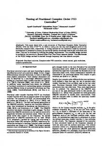
Figure 1: Gain margin - = Ziegler-Nichols (1942) + = Astrom-Hagglund (1995) o = Cohen-Coon (1953) * = Chien et al. (1952) – reg – 20% o.s.
Classical controller – ⎛ 1 ⎞ ⎛ 1 + Td s ⎞ G c (s) = K c ⎜ 1 + ⎟⎜ ⎟ Ti s ⎠ ⎝ 1 + Td s N ⎠ ⎝ Shinskey (1996) – min. IAE Shinskey (1994) – min. IAE
Regulator 157 . τm 0.93 Kmτ m
Ratio of τ m to Tm 0.56τ m
0.93 Kmτ m
160 . τm
0.58τ m , N = 10
0.93 K mτ m
1.48τ m
0.63τ m , N = 20
Figure 2: Phase margin Figure 3: Gain margin
4. SIMULATION RESULTS
Space considerations dictate that only representative simulation results may be provided. In these results, approximate gain margin and phase margin are analytically calculated, using the method outlined by Ho, et al. (1996), for processes compensated using an appropriately tuned PID controller. The MATLAB package has been used in the simulations. The same tuning rules are used in Figures 1 and 2; similarly, the same tuning rules are used in Figures 3 and 4, and in Figures 5 and 6.
Ratio of τ m to Tm Figure 3: Gain margin - = Abbas (1997) – 0% o.s. + = Abbas (1997) – 10% o.s. o = Abbas (1997) – 20% o.s.
- = += o=
Preprints of Proceedings of PID ’00: IFAC Workshop on Digital Control, Terrassa, Spain, April 4-7, 2000, pp. 242-247.
Ratio of τ m to Tm Ratio of τ m to Tm Figure 4: Phase margin
Ratio of τ m to Tm Ratio of τ m to Tm Figure 5: Gain margin - = Tsang et al. (1993) – ξ = 0.1 + = Tsang et al. (1993) – ξ = 0.4 o = Tsang et al. (1993) – ξ = 0.7 * = Tsang et al. (1993) – ξ = 1.0
These simulations reveal the following: (1) Typically, the analytical calculation of the phase margin is real (and positive) in a restricted range of ratios of τ m Tm ; the range allowed is very limited for many tuning rules. Typically, the gain margin is real and positive over a much wider range. (2) The process reaction curve tuning rule of Cohen and Coon (1953) gives rise to a smaller gain margin (and approximately equal phase margin) to that of Ziegler and Nichols (1942), indicating that the closed loop response associated with the application of the former tuning rule may be expected to be more oscillatory. This is compatible with application experience. (3) Both the gain and phase margins are larger for the tuning rule of Abbas (1997), when the design criteria is to achieve 0% overshoot in the closed loop response, compared to when the design criterion is to achieve 20% overshoot. This is as expected. (4) The tuning method of Tsang et al. (1993) gives a constant gain margin and an almost constant phase margin. The nature of this tuning rule has interesting similarities to the tuning rules that give rise to constant gain and phase margins when a PI controller is used (O’Dwyer, 2000a). It is also clear that the tuning rules may be used at ratios of τ m Tm outside the normally recommended range of 0.1 to 1.0. (5) If the data in Figures 1 and 2 is compared with the corresponding data (O’Dwyer, 2000a), it is clear that the gain margin of the PID controller is significantly lower than that of the corresponding PI controller, when the Ziegler and Nichols (1942) tuning rules are used. The phase margin is also mostly higher for the PI controller. This indicates that the PID controller should offer a faster response (to a step input in servo mode, for example). Similar comments apply for many other tuning rules. A fuller panorama of simulation results show that stability tends to be assured when a PI controller tuning rule is used. Thus, a cautious design approach is to use a PI controller, with an appropriate tuning rule, particularly at larger ratios of time delay to time constant.
5. CONCLUSIONS
Ratio of τ m to Tm Ratio of τ m to Tm Figure 6: Phase margin
A large number of PID controller tuning rules have been defined in the literature to compensate SISO processes with time delays. The paper has presented a flavour of the variety of tuning rules defined. Some results associated with the analytical calculation of the gain margin and phase margin of compensated delayed systems, as the ratio of time delay to time constant varies, have also been presented. Future work will concentrate on further analytical evaluation of the robustness of delayed processes compensated using tuning rule based PID controllers.
Preprints of Proceedings of PID ’00: IFAC Workshop on Digital Control, Terrassa, Spain, April 4-7, 2000, pp. 242-247. REFERENCES
Tm
Abbas, A. (1997). A new set of controller tuning relations. ISA Transactions, 36, pp. 183-187. Astrom, K.J. and Hagglund, T. (1995). PID Controllers: Theory, Design and Tuning, page 139, Instrument Society of America, Research Triangle Park, North Carolina, 2nd Edition. Chien, K.-L., Hrones, J.A. and Reswick, J.B. (1952). On the automatic control of generalised passive systems. Transactions of the ASME, February, pp. 175-185. Chien, I.-L. (1988). IMC-PID controller design - an extension. Proceedings of the IFAC Adaptive Control of Chemical Processes Conference, pp. 147-152, Copenhagen, Denmark. Cohen, G.H. and Coon, G.A. (1953). Theoretical considerations of retarded control. Transactions of the ASME, May, pp. 827-834. Cluett, W.R. and Wang, L. (1997). New tuning rules for PID control. Pulp and Paper Canada, 3, pp. 52-55. Ford, R.L. (1953). The determination of the optimum process-controller settings and their confirmation by means of an electronic simulator. Proceedings of the IEE, Part 2, 101, April, pp. 141-155 and pp. 173-177. Fruehauf, P.S., Chien, I.-L. and Lauritsen, M.D. (1993). Simplified IMC-PID tuning rules. Proceedings of the ISA/93 Advances in Instrumentation and Control Conference, McCormick Place, Chicago, Illinois, pp. 17451766. Hang, C.C., Lee, T.H. and Ho, W.K. (1993). Adaptive Control, page 76, Instrument Society of America, Research Triangle Park, North Carolina. Ho, W.K., Gan, O.P., Tay, E.B. and Ang, E.L. (1996). Performance and gain and phase margins of wellknown PID tuning formulas. IEEE Transactions on Control Systems Technology, 4, pp. 473-477. Kaya, A. and Scheib, T.J. (1988). Tuning of PID controls of different structures. Control Engineering, July, pp. 62-65. Murrill, P.W. (1967). Automatic control of processes. International Textbook Co. O’Dwyer, A. (2000a). A summary of PI and PID controller tuning rules for processes with time delay: Part 1: PI controller tuning rules. Proceedings of IFAC Workshop on Digital Control, Terrassa, Spain. O’Dwyer, A. (2000b). PI and PID controllers for time delay processes: a summary. Technical Report AOD/00/01, Dublin Institute of Technology, http://www.docsee.kst.ie/aodweb/. Rovira, A.A., Murrill, P.W. and Smith, C.L. (1969). Tuning controllers for setpoint changes. Instruments and Control Systems, 42, December, pp. 67-69. Shinskey, F.G. (1988). Process Control Systems Application, Design and Tuning. McGraw-Hill Inc., New York, 3rd Edition.
Shinskey, F.G. (1994). Feedback controllers for the process industries. McGraw-Hill Inc., New York. Shinskey, F.G. (1996). Process Control Systems Application, Design and Tuning. McGraw-Hill Inc., New York, 4th Edition. Smith, C.A. and Corripio, A.B. (1985). Principles and practice of automatic process control, John Wiley and Sons, New York. Tsang, K.M., Rad, A.B. and To, F.W. (1993). Online tuning of PID controllers using delayed state variable filters, Proceedings of the IEEE Region 10 Conference on Computer, Communication, Control and Power Engineering, 4, pp. 415-419. Tsang, K.M. and Rad, A. B. (1995). A new approach to auto-tuning of PID controllers. International Journal of Systems Science, 26, pp. 639-658. Witt, S.D. and Waggoner, R.C. (1990). Tuning parameters for non-PID three-mode controllers, Hydrocarbon Processing, June, pp. 74-78. Zhuang, M. and Atherton, D.P. (1993). Automatic tuning of optimum PID controllers. IEE Proceedings, Part D, 140, pp. 216-224. Ziegler, J.G. and Nichols, N.B. (1942). Optimum settings for automatic controllers. Transactions of the ASME, November, pp. 759-768.
APPENDIX: LIST OF SYMBOLS AND ABBREVIATIONS USED G c (s) = PID controller transfer function IAE = integral of absolute error, ISE = integral of squared error ISTES = integral of squared time multiplied by error, all to be squared ISTSE = integral of squared time multiplied by squared error ITAE = integral of time multiplied by absolute error K c = Proportional gain of the controller, K m = Gain of the process model N = Indication of the amount of filtering on the derivative term o.s. = overshoot R(s) = Desired variable Td = Derivative time of the controller, Ti = Integral time of the controller Tm = Time constant of the process model, Tu = Ultimate time U(s) = manipulated variable, Y(s) = controlled variable λ = Parameter that determines robustness of compensated system. ξ = damping factor of the compensated system τ m = time delay of the process model