response time and force limit their use in aircraft applications where space is a .... Figure 3. Velocity, Displacement, and Applied Voltage at 5 Hz for a Thunder.
Mat. Res. Soc. Symp. Proc. Vol. 785 © 2004 Materials Research Society
D11.8.1
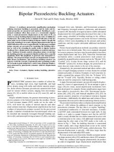
Piezoelectric Actuators for Synthetic Jet Applications Karla Mossi1 and Robert Bryant2 1 Virginia Commonwealth University, Richmond VA 23284, U.S.A 2 NASA Langley Research Center, Hampton VA 23681, U.S.A. ABSTRACT Synthetic jets have been identified and utilized widely in airflow control applications. These jets of air are usually created by the use of compressed air, or an electromechanically driven vibrating platform. All of these approaches produce desired results in airflow-control such as enhanced lift and increased maneuverability. Despite the results however, system weight, size, response time and force limit their use in aircraft applications where space is a premium. The objective of this study is to characterize the relevant properties for the design of a synthetic jet utilizing three types of piezoelectric actuators as mechanical diaphragms. The limiting parameters of the actuators for this application are shape and volumetric space. Thus, the actuators were circular with a diameter of 6.35 cm, and overall device cavity volume no larger than 147.5 cm3 on a 7 cm x 7 cm areal coverage. The actuators tested were pre-stressed curved metallic unimorphs, bimorphs, and radial field diaphragms. These piezoelectric elements were chosen because of their geometry, quasi-isostatic topography and overall free-displacement. Each actuator was affixed about its perimeter in a cavity, and relevant parameters such as clamped displacement, and jet velocity though a pre-determined dimensional slot, were measured. INTRODUCTION Piezoelectric actuators have been in existence for several decades, however, their application as part of complete mechanisms, machines, or devices are rare. One of the main reasons for failure to find a suitable application for these devices are the boundary conditions dictated by the environment that the device would be used [1, 2]. Piezoelectric actuators such as moonies [3], rainbows [4, 5], unimorphs [6], thunders [7,8,9], and bimorphs [10,11] have been investigated and their properties and behavior are well documented. Predicting their performance in an application however, is still not available, especially when working with circular actuators. A new type of circular actuator with inter-digitated electrodes, radial field diaphragms, RFD, has been designed and characterized [12,13]. Preliminary work shows that RFDs have properties that may be key in an application design. The overall objective of the project is to use these active diaphragms in a synthetic jet cavity no larger than 7.62 cm x 7.62 cm x 2.54 cm. Relevant parameters such as clamped displacement, frequency, and capacitance were measured in a previous study and the limitations and advantages were described [14]. These preliminary results showed that none of the three actuators possessed all of the characteristics needed to design a synthetic jet to be used for an effective flow control mechanism. Synthetic jets as means of flow control devices have been proven to be effective as means to provide flow control reducing drag and enhancing mixing [15, 16]. These synthetic jets have been produced with speakers, compressed air, air pumps, and bimorph diaphragms among others
D11.8.2
[17, 18, 19]. All of the above techniques however add weight, require real estate, and add complexity to an airplane making these options not feasible or practical. This study concentrated on three different types of actuators enclosed on a cavity with a slot to produce a synthetic jet actuator with a zero net mass flow rate. The piezoelectric actuators were tested in a cavity of constant size equipped with a slot. The actuators were driven with different types of waveforms and frequencies. The results obtained in this phase will be utilized to determine a design for a piezoelectric synthetic jet system. EXPERIMENTAL SETUP The elements used for testing consisted on three different groups, bimorphs, pre-stressed curved Unimorphs (Thunder), and Radial Field Diaphragms (RFD). All of the devices had a diameter of 63.5 mm (2.5 inches). The bimorph utilized consisted of two bonded piezoelectric layers manufactured by Piezo Systems, Inc. model number T216-A4NO-573X. The device is manufactured with Type 5A material with nickel electrodes and a total thickness of 4.1 mm (16 mil) and each PZT layer 1.9 mm thick. The Thunder devices manufactured by Face International Corporation consisted of layers of stainless steel type 304, 0.254 mm thick, PZT type 5A, 0.254 mm thick, and copper, 0.0254 mm thick, laminated using SI adhesive in between each layer. The last group was the radial field diaphragms, RFD, manufactured by NASA Langley Research center. These devices consist of one PZT layer laminated in between Kapton film with copper inter-digitized electrode patterned etched into it. Distance between electrodes for this set has been optimized from previous results2. A schematic of the layout of these three types of devices is shown in Figure 1a, 1b, and 1c. Clamping Mechanisms: It has been proven that the boundary conditions that a piezoelectric actuator is going to be subjected to in an application have a significant impact on the final performance of the device. For instance, Liew states that different boundary conditions and applied voltages affect the shape control of piezo-laminated composite beams2. For this reason the characterization of circular devices becomes crucial for the design of an application. The basic layout for the three types of devices consists of a circular cavity on a rectangular plate, where the top and bottom layer are held together with screws Figure 2. The clamping inside the cavity for each actuator is maintained as constant as possible, however due to the unique characteristics of each actuator a specific clamping mechanism for each device type was designed shown in Figure 2. For the bimorph a groove was machined on the cavity that is reinforced with neoprene rubber to provide both a cushion and a seal. The thunder device has a small tab made of stainless steel (the bottom layer of the device is larger than the rest of the layers), 1.27 mm around the perimeter of the device. These actuators can be clamped easily between the top and bottom layers of the holder. Approximately 3 mm thick silicon rubber was used to provide a seal between the top and bottom clamping layers. The RFD provided the easier clamping method of all the pieces, since the film can be clamped easily without the need to utilize any sealing material or specially made cavities. The cavity dimensions consist of two plates with a total height of 1.0 cm, length of 8.89 cm, and width of 8.85 cm with a top plate cover. The top cover plate shown on the schematic of Figure 2, has a top plate with a slot width of 0.05207 cm and length of 3.49 cm which constitutes the slot for producing an air jet. For this study this is the only size slot tested. All of the actuators were fastened between the top and bottom layer of the cavity as described above depending on the actuator type.
D11.8.3
(a)
(b)
(c)
Figure 1. Schematic of (a) Bimorph, (b) Thunder, and (c) RFD The measurements performed included jet velocity at 2 mm from the slot exit, displacement of the actuator at the opposite end, and applied voltage, frequency and waveform. The equipment utilized included a hot wire anemometer coupled with an IFA-1000 flow analyzer, a LeCroy oscilloscope; a TREK voltage amplifier model PZD700, an HP33120A signal generator, a positioning system, and a non-contact Laser Nais LM10 system. All the instruments were controlled and monitored through a PC using LabView® software. RESULTS AND DISCUSSION The hot wire anemometer was calibrated in a 60 m/s uniform pipe flow. Driving voltages and frequencies were different for each actuator according to their characteristics utilizing three different waveforms for all of the actuators, namely, a sine wave, a square wave, and a saw tooth. The results obtained for each piezoelectric actuator are described below and relevant results are presented. Thunder Actuators The clamping mechanism for these actuators consisted of a machined cavity filled with silicon rubber to accommodate its bowed shape. The device is placed between the plates with screws using a torque wrench precisely at 40 oz-in (0.2826 N⋅m). Even though these actuators should be the most robust and high force piezoelectric composites because of the materials utilized on their construction, namely stainless steel and copper, Thunder actuators produced the smallest air-jet velocity independently of the driving voltage and waveform applied. The first set of tests consisted on waveform variations starting with a sinusoidal waveform at different voltages and frequencies. These tests did not produce a measurable air jet velocity. Because of the lack of success with a sinusoidal waveform, a stronger stroke was needed and a square Jet Velocity
Actuator Movement Neoprene Rubber
Center Displacement
Figure 2. Schematic of the Synthetic Jet Actuator Cavity
D11.8.4
waveform was then tested. This waveform produced a double jet, shown in Figure 3a, with the velocity peaking at the rise and fall of the square wave producing suctioning and blowing with peak velocities of 4.196 m/s and 2 m/s respectively. The displacement curve also shown in Figure 3a shows a vibrating reaction with a maximum value of 0.0525mm of displacement. Such reaction could be due to the clamping mechanism utilized and other clamping mechanisms could be used to take advantage of this effect, however clamping mechanisms effects were not tested on this study. Finally, based on the observed results, a saw tooth waveform was tested. The results, shown in Figure 3b, were slightly higher than with a square wave producing a single peak at 4.525m/s. Note that the maximum displacement obtained with this waveform was 0.0504 mm, 4% less than with a square wave which is not very significant. Other tests performed with this actuator included different applied voltages and frequencies. Results obtained produced varying results that were not consistent. Such behavior may be due to mechanical clamping conditions and require further investigation. Radial Field Diaphragms, RFD Actuators Radial field diaphragms were the easiest element to clamp mechanically. That may be the reason for the most consistent results when varying voltage and frequency. The same type of performance with respect to driving waveform was observed on the RFD devices as well as the Thunder devices This indicates that the driving waveform may be responsible for the production of a single defined jet in a cavity and is independent of the actuator utilized. That is a square wave produced two peaks as well as not enough jet velocity with a sinusoidal waveform. When using a saw tooth waveform a maximum value of speed is reached before reaching maximum operating voltage, 1000Vpp. These results are shown in Figure 4, which also shows that the displacement performance of the RFD actuator follows the same trend of the peak velocities measured with the hot wire anemometer. Peak velocities of 20.7 m/s and displacement of 0.104 mm were recorded. Other tests varying frequency need to be performed, however due to the limitations on the RFD, characterized on previous work, these tests were not performed.
5
200
0.080 0.070
0.040 0.030
4
100
3
0
2
-100
0.020 0.010 0.000
1
Voltage Applied
0.050
0.050 0.040 0.030
-300
0.1
0.2
0.3
0.4
0.5
5
200
4
100
3
0
2
-100
1
-200
0.020 0.010
0.0
300
0.060
-200
0
6
0.000
0
-300
0.0
0.2
0.3
0.4
time (s)
time (s)
Velocity
(a) Square Waveform
0.1
Displacement
Voltage
(b) Saw Tooth Waveform
Figure 3. Velocity, Displacement, and Applied Voltage at 5 Hz for a Thunder Synthetic Jet
0.5
Voltage Applied
300
Velocity (m/s)
6
0.060
Velocity (m/s)
Displacement (mm)
0.070
Displacement (mm)
0.080
D11.8.5
Bimorph Actuators A specially build cavity filled with silicon rubber was designed around the actuator to avoid putting pressure on the device itself to avoid fracture. Despite its fragility and brittleness, this actuator produced the highest jet velocity when using a saw tooth waveform at 5 Hz with a maximum speed of 33 m/s and -180 Volts. These frequency and waveform behavior were also observed for the thunder and RFD devices. To illustrate this characteristic, frequency measurements were performed using this voltage and waveform, see Figure 5. Once again the most jet velocity is observed at 5 Hz suggesting that these characteristic may be due to cavity size and geometry of the slot and not the actuator utilized. By using the theory developed for a Helmholtz Resonator, the resonant frequency of the cavity was calculated to be at approximately 220 Hz. This frequency value was not measured so other mechanisms may be influencing these results. Further experiments are being performed to investigate this phenomenon. CONCLUSIONS Experiments were performed utilizing three different types of piezoelectric actuators as synthetic jets, thunder actuators, radial field diaphragms, and bimorphs. All of the actuators were circular diaphragms clamped with specific boundary conditions for each actuator. A thunder device was clamped between the cavity plates and silicon rubbed to shape the cavity to the shape of the actuator; a RFD actuator was clamped simply around its perimeter; and the bimorph was clamped in a cavity machined to size utilizing silicon rubber on both sides to avoid putting excessive pressure on the device. All of the actuators showed maximum speed at 5 Hz with a saw tooth waveform indicating that these characteristics may be related to cavity size and geometry only and not the actuators displacement performance. The thunder device produced the smallest velocity, 4.196 m/s, followed by an RFD, 20.7 m/s, and the bimorph with the highest speed at 33 m/s. Tests with clamping mechanisms, frequency variations, cavity sizes, and slot dimensions need to be performed to further investigate the behavior of these actuators as synthetic jets. 0.12
24 Velocity Displacement Regression Displacement Regression Velocity
35
0.08
12
0.06 8
0.04 4
Velocity (m/s)
30
16 Velocity (m/s)
40
0.10 Displacement (mm)
20
25 20 15 10 5
0.02
0
0 0
0
200
400
600
800
1000
0.00 1200
20
40
60
80
100
120
Frequency (Hz)
Peak to Peak Voltage
Figure 4. Velocity and Displacement variations with Voltage for an RFD Synthetic Jet Actuator using a Saw tooth waveform at 5 Hz
Figure 5. Bimorph Jet Velocity variations with Frequency using a Saw Tooth Waveform at -180 Volts peak.
D11.8.6
ACKNOLEDGEMENTS This work is supported by NASA Langley Research Center, Grant NAG-1-03002. Also we would like to thank the following students, Justin Costley, Jonathan Moon, and Juan Gomez. REFERENCES 1. J. Mulling, T. Usher, B. Dessent, J. Palmer, P. Franzon, E. Grant, A. Kingon, Sensors and Actuators A, 94, 19-24 (2001). 2. K. M. Liew, H. K. Lim, M. J. Tan, X. Q. He, Computational Mechanics, 29, 486-497 (2002). 3. G. Haertling, J. of the Amer. Ceramic Soc., Vol. 82, 4, 797-1615, (1999). 4. W. Y. Shih, W. H. Shih, I. A. Aksay, J. Am. Ceram. Soc., 80 [5] 1073-78 (1997). 5. G. H. Haertling, Am. Ceram. Soc. Bull., 73, 93-96 (1994). 6. T. Idogaki, T. Tominaga, K. Senda, N. Ohya, T. Hattori, Sensors and Actuators A, 54, 760764 (1996). 7. R. W. Schwartz, M. Narayanan, Sensors and Actuators A, 101, 322-331 (2002). 8. Z. Ounaies, K. Mossi, R. Smith, J. Bernd, Low-Field and High-Field Characterization of Thunder Actuators, Proc. SPIE Smart Struct. Mater., 4333, 399-407 (2001). 9. K. Mossi, R. Bishop, Characterization of Different Types of High Performance Thunder Actuators, Proc. SPIE Smart Struct. Mater., 3675, 738-743 (1999) 10. D. J. Cappelleri, M. I. Frecker, T. W. Simpson, A. Snyder, “Design of a PZT Bimorph Actuator Using a Metamodel-Based Approach,” Transactions of the ASME, Vol 124, 354357, (2002). 11. Q. Wang, Q. Zhang, B. Xu, R. Liu, E. Cross, Journal of Applied Physics, 86 [6], 3352-3360, (1999). 12. R. Bryant, R. Effinger IV, B. Copeland Jr, Radial Field Piezoelectric Diaphragms, Proceedings of Actuator 2002, A1.3, June 10-12 (2002). 13. R. Bryant, R. R. Effinger IV, I. Aranda Jr., B. Copeland, E. Covington III, Active Piezoelectric Diaphragms, Proc. of SPIE Active Materials, 4699-40, (2002). 14. Mossi, Karla, and Bryant, Robert, Pre-Stressed Circular Actuators, to appear at Proceeding of the American Ceramic Society, 2003. 15. Mallinson, S.G.; Reizes, J.A.; Hong, G.; Buttini, M., Synthetic jet actuators for flow control, Proc SPIE Int Soc Opt Eng, vol. 3891, p 146-156, (1999). 16. Mautner, Thomas S., Application of synthetic jets to low Reynolds number biosensor microfluidic flows for enhanced mixing: A numerical study using the lattice Boltzmann method, Proc SPIE Int Soc Opt Eng, vol. 4937, p 136-149, (2002). 17. Jenkins, L., Gorton, A., and Anders, S., Flow control Device Evaluation for an internal Flow with an Adverse Pressure Gradient, 40th AIAA Aerospace Sciences Meeting and Exhibit, AIAA-2002-0266, (2002). 18. Chen, F., and Beeler, G., Virtual Shaping of a Two-Dimensional NACA 0015 Airfoil Using Synthetic Jet Actuator, AIAA-2002-3273, (2002). 19. Whitehead, J. A., and Gursul, I., Aerodynamics and Propulsion of Synthetic Jet Based Micro Air Vehicles, AIAA-2003-4004, (2003).