The new version supports the two kinds of Petri nets we have devel- ... tirobot system, we have designed two Petri net-based frameworks for (i) tracking and.
EXHOST-PIPE PIPE Extended for Two Classes of Monitoring Petri Nets Olivier Bonnet-Torrès1,2, Patrice Domenech3, Charles Lesire1,2 , and Catherine Tessier1 1
O NERA -C ERT /DCSD, 2, avenue Édouard Belin, 31055 Toulouse cedex 4, France 2 E NSAE -Supaero, 10, avenue Édouard Belin, 31055 Toulouse cedex 4, France 3 at Onera-DCSD for a training period Feb-June 2005 {olivier.bonnet, charles.lesire, catherine.tessier}@onera.fr
Abstract. This paper presents the E XHOST-PIPE software: an extension of PIPE – Platform Independent Petri net Editor – that complies with our own specifications. The new version supports the two kinds of Petri nets we have developed: particle Petri nets and plan Petri nets. E XHOST-PIPE also supports colours, modularity, time, guards, differential equations. . . The Petri net player has been extended and specific algorithms (such as an estimation process and specific reduction rules) have been implemented as plug-in modules.
1 Introduction In the context of multiagent system monitoring, e.g. a crew-aircraft system or a multirobot system, we have designed two Petri net-based frameworks for (i) tracking and predicting the (possibly conflicting) states of a human-controlled system and (ii) supervising and controlling a team of autonomous robots. As the question of the implementation arose, it was decided not to develop yet another tool from scratch, but to start from an existing open-source software. A review of the tools available on the Internet led us to select PIPE – Platform Independent Petri net Editor – for its clear and intuitive interface, its simulation module, its comprehensive UML documentation and the possibility to modify the Java code quite easily. The original PIPE software1 [1] manages ordinary Petri nets. It applies the objectoriented Model-Controller-View architecture pattern to implement several Petri net analysis plug-in modules. The architecture separates the graphical rendering of the Petri nets (the View), the processing of user requests (the Controller) and the Petri net structure itself including state and data (the Model). The model layer is also responsible for PNML input/output management. With little modification the graphical interface manages multiple Petri nets. As for the animation the original player is very simple and fires either once at user click or a user-specified number of randomly chosen transitions. The paper is organised as follows: 1. an explanation of the specifications will be provided first; the tool must be able to deal with the two special kinds of Petri nets that we have designed; 1
http://pipe2.sourceforge.net
S. Donatelli and P.S. Thiagarajan (Eds.): ICATPN 2006, LNCS 4024, pp. 391–400, 2006. c Springer-Verlag Berlin Heidelberg 2006 �
392
O. Bonnet-Torrès et al.
2. a presentation of the architecture; the tool is evolutive thanks to the distribution of object behaviour knowledge; 3. a description of some specific operations, embedded in the tool as modules; they provide specific algorithms to deal with special nets.
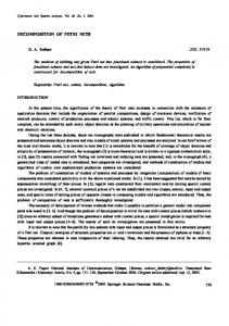
2 Specifications The high level specifications were very simple: the PIPE-derived tool had to allow us to represent and play the two kinds of Petri nets we have designed for our applications and implement specific algorithms on these nets. The specifications are detailed hereafter. 2.1 Particle Petri Nets Particle Petri nets [2] have been designed for hybrid numerical-symbolic situation monitoring and conflict detection in human-supervised systems. The particle Petri net model (Fig. 1) is based on differential Petri nets and features: (1) numerical places and transitions that model the numerical behaviour of the system (using differential equations and guards) and (2) symbolic places and transitions that model the symbolic behaviour of the system (events and external actions). The estimated state of a hybrid system is represented thanks to multiple tokens: par(i) ticles πk+1|k – meaning particle number i estimated at time k + 1 knowing the observation at time k – carry the numerical state vector of the system and evolve within the (j) numerical places; configurations δk+1|k – meaning configuration number j estimated at time k + 1 knowing the observation at time k – carry the symbolic state vector of the system and evolve within the symbolic places. A possible state of the system of Fig. 1
Fig. 1. The particle Petri net of a flight phase. It represents both the behaviour of the aircraft and the interactions between the crew and the autopilot.
E XHOST -PIPE PIPE Extended for Two Classes of Monitoring Petri Nets
393
5000ft to 3000ft heading 144 speed 180kt
z < 3000ft
random generation
3000ft heading 144 speed 180kt to 120kt
Flaps
d < 7NM
Initialisation
γ (1) γ (3) γ
(2)
ranking
weighting
m5,0= ( γ (5), δ (0) )
z < 3000ft
z < 3000ft
z < 3000ft
z < 3000ft
m5,1= ( γ (5), δ (1) )
m6,0= ( γ (6), δ (0) ) Flaps
Flaps
Flaps
Flaps
m6,1= ( γ (6), δ (1) ) d < 7NM
estimated marking correction graph
Correction
d < 7NM
d < 7NM
d < 7NM
Prediction
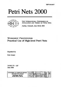
Fig. 2. The particle Petri net-based estimation process
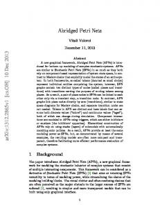
is represented by marking mi,j,l = (π (i) , δ (j) , δ (l) ), where π (i) is a possible state of the aircraft, δ (j) is a possible mode of the autopilot and δ (l) is a possible belief of the crew. The particle Petri net-based estimation (Fig. 2) is a two-step process: a prediction of the system state by having the estimated marking evolve within the net according to specific firing rules and differential equations, and a correction of the predicted states according to an observation of the system. The correction consists in weighting/ranking the tokens to update the estimated marking of the Petri net and construct a correction graph used to detect inconsistent behaviours of the system [3]. Specifications: the PIPE-derived tool has to allow two kinds of places to be created via the GUI and dealt with with the Petri net player: (1) the symbolic places and (2) the numerical places that are linked to differential equations and whose tokens are numerical vectors. Receptivities and conditions have to be associated to transitions. As far as the simulation is concerned, the Petri net player has to take into account the specific firing rules for prediction and the whole estimation process has to be implemented. 2.2 Plan Petri Nets Plan Petri nets and their specific reduction rules [4, 5] have been designed for robot team plan supervision and control. A plan is a course of tasks to be realised in order to carry out a mission. Tasks are associated with the places and have time and resource requirements. Time requirements are start-time, finish-time and duration intervals. A team of service-performing robots is allocated to the mission. A plan is one possible way to complete the mission through actions with the given robotic team while respecting time and resource constraints. The mission plan Petri net (Fig. 3) is a coloured time Petri net2 transcription of the plan. For a complex mission the mission plan Petri net might be too detailed to provide an efficient interface for plan execution monitoring. Hence the plan is abstracted into a layered plan. The transformation is carried out by reducing some structures in the mission 2
Start-times and finish-times correspond to a t-time Petri net. Durations are associated to the places and modify the behaviour by adding some properties of the p-timed Petri nets.
394
O. Bonnet-Torrès et al.
Fig. 3. A mission plan. Places correspond to tasks. pi tl
tk pi
tl (a)
pj
pi
pi
... 1
pi
2
1
pt p ik
...
pj
pi1
pi
t j1
tk (b)
(c)
pik (d)
pk
1
(e)
tk
1
t j2 pl1 pk
tn1
...
tk m
... ...
plm tn m
2
(f)
pj
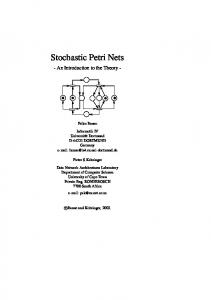
Fig. 4. Reduceable structures: (a) source, (b) sink, (c) parallel, (d) sequence, (e) transfer, (f) choice
plan Petri net (Fig. 4): source (agent arrival), sink (agent withdrawal), sequence (sequential activities), parallel (concurrent activities), transfer (transfer of a robot from a task to another) and choice (alternate activities). The reduction yields a plan organised as a hierarchy and represented as a modular coloured time Petri net (Fig. 5). Each reduction step structures a part of the team: a reduced place corresponds to a subteam whose members are the robots or subteams corresponding to the places that have been reduced. Hence the reduction provides a team organised as a hierarchy that changes with the marking (Fig. 5, lower left corner). The dynamic team organisation allows the mission execution to be monitored at different levels of abstraction. The control of individual robots must be performed at the local level. The plan Petri net is hence projected onto individual teammates: the leaf-places that involve the concerned robot are kept as well as all their ancestors in the hierarchy of places (Fig. 6).
E XHOST -PIPE PIPE Extended for Two Classes of Monitoring Petri Nets 0
depth
3
2
1
395
p2 p13 p12
p0
mission
●
pm
●
p(1−* −9)+
p13 −15
p2
p1 (2 −...−10) ●
p1−*− 9
●
●
p 2−...−10
p11
p*
●
p9
depth A AA
3
AAA
4
ab g
AB b c e f AAB a g d ab g
p1 ● ●
p6
mission
● ● ●
p7
B
p0
p3|4
●
p(3|4)−6 p14
X
0 1
2
1
p5 ●
p10
●
p4 ●
p11 p16
0
depth p3
●
●
2
p 15
p +(13−15) 12
g
depth 0 p8
X
1
A B 2 AA AB 3
p16
p5
p*
p9
p8
a d g
Fig. 5. Team plan Petri net and hierarchy associated with the Fig. 6. Team plan projected on agent d current marking
Specifications: the PIPE-derived tool has to allow several nets to be drawn via the GUI and played at the same time. Defining transition fusion sets and place fusion sets has to be possible. The specific reduction rules have to be implemented: transition and place fusion sets have to be created automatically, special places (as the “transfer” places) have to be created and the different reduced Petri nets have to be played at the same time. Moreover, consistent and semantically valid names for the fused places have to be assigned automatically. The tool also has to be able to project a plan organised as a hierarchy onto any given individual.
3 Architecture As the original version of Pipe [1], E XHOST-PIPE is organised according to a ModelView-Controller architecture. In this section we will focus on the model itself. Due to the very different natures of the Petri nets to deal with, some changes have been made. In particular the firing rules associated to our models are more complicated than in ordinary Petri nets and have been relocated within the transition objects themselves. For the same reasons the animator has been modified as well. 3.1 Tokens, Places and Transitions The basic Petri net object in E XHOST-PIPE models a modular time Petri net. It decomposes into a set of coloured time Petri nets and a set of fusion sets (see Sect. 3.2). Each coloured Petri net has a set of places and a set of transitions that are specialised according to the type of Petri nets it models. The tokens allowed in the places are also specialised as they bear various types of information. The features that have been designed are the following:
396
O. Bonnet-Torrès et al.
Differential Equation
Marking
Fig. 7. A particle Petri net and the information attached to numerical place p0 : the differential equation is a Descent and the marking is detailed (the values of the vectors are given)
1. Ordinary token: the token corresponds to a coloured token. The allowed colour sets do not convey complex information yet. 2. Configuration: the token corresponds to a vector of discrete state variables. It models a configuration of the system under monitoring. 3. Particle: the token corresponds to a vector of continuous state variables. It models a numerical state of the system under monitoring. 4. Ordinary place: the place comes with a colour function and time specifications. The time specifications comprise a minimum duration, a maximum duration and a most-likely duration. If it pertains to a place fusion set, its marking is common with all places in the fusion set. 5. Symbolic place: the place represents the discrete state of the monitored system. It accepts configuration tokens. 6. Numerical place (Fig. 7): the place represents the way the particle parameters evolve. It is attached a differential equation. 7. Transfer place: the place models the transfer of an agent from one branch to another in a plan Petri net. It behaves exactly the same way as an ordinary place. 8. Ordinary transition: the transition is responsible for firing in a coloured time Petri net. The time specifications are given in the form of a firing time interval. If it pertains to a transition fusion set, it has to check whether the fusion set is enabled, i.e. if all transitions in the fusion set are enabled. 9. Symbolic transition: the transition fires to acknowledge event occurrences or to predict the possible external actions applied to the system. 10. Numerical transition: the transition is guarded with some particle parameter threshold values. These elements when combined constitute a Petri net layer. As described above several layers may be linked in a modular Petri net. 3.2 Modular Petri Nets In a modular Petri net [6, 7], each Petri net layer is a module. Several modules may be linked by sharing transitions and/or places. Each shared node constitutes a fusion set.
E XHOST -PIPE PIPE Extended for Two Classes of Monitoring Petri Nets File management
Petri net objects
397
Animation buttons
Displayed information selection tabs Modular Petri net tabs
Subnet tabs
Information pane
Fig. 8. Screenshot presenting the different parts of the interface. The modular Petri net shown is obtained from Fig. 3 after reduction.
The functioning rules are the following: 1. Place fusion set: if one place in the fusion set is marked, its marking is shared with the other fused places, i.e. all transitions downstream the places in the fusion set are enabled. These transitions enter in a conflict between modules. A place may appear in different fusion sets, therefore: (a) if it is marked, every place in all fusion sets can use the marking; (b) if it is not marked and only one other place is marked, only the places in the corresponding fusion set share the marking; it is not shared from one fusion set to another. 2. Transition fusion set: the transitions in the fusion set may fire only if all transitions in the set are enabled. The firing marks all downstream places in all modules and decreases the marking in all upstream places. A transition may belong to several fusion sets, in which case: (a) if two or more fusion sets are enabled, there is a conflict; (b) if only one fusion set is enabled, there is no conflict: it fires. Hierarchical Petri nets [8] are represented by modular Petri nets [7]. A master place in a hierarchical Petri net is equivalent to a place whose upstream and downstream transitions are fused with the corresponding transitions within the slave subnet. The user interface has been modified to take into account the modular Petri nets. The basic interface element is a modular Petri net, whose selection tabs call the different layers. All places and transitions can be added into fusion sets and a side tab in the left panel shows the properties of the fusion sets (Fig. 8). 3.3 Animation: Playing the Nets E XHOST-PIPE features both Petri net models and manages fusion sets of places and transitions. Consequently, the original animator had to be modified: specific enabling
398
O. Bonnet-Torrès et al.
conditions and firing rules are contained in the transitions themselves and fusion sets are defined within the modular Petri net object. The modified animation process now: 1. checks whether each transition is enabled: when a transition is possibly enabled (according to the Petri net fundamental equation), the associated specific condition is checked (colours, incoming events, numerical condition. . . ), 2. checks whether the fusion sets are enabled, 3. and finally follows one of the four implemented firing behaviours: (a) prompt mode: the animation asks the user to choose the transition (or fusion set) to fire; (b) prompt on conflict mode: if there is only one enabled transition (or fusion set), the animation makes it fire, otherwise the user is asked to choose the transition to fire; (c) random mode: the animation randomly draws an enabled transition (or fusion set) and makes it fire; (d) timed mode: the animation takes into account the time specifications: a timestamp is randomly drawn for each transition firing or place duration interval, making use of a maximum likelihood parameter and a dilution factor. The transitions are drawn in ascending order of drawn firing times. If a firing time interval is violated the animation exits with a time violation message. 3.4 Estimation of Particle Petri Nets All the algorithms/operations that are useful for the estimation process have been implemented in dedicated classes: prediction, weighting, resampling, ranking. . . The core of the estimation process is to perform a prediction of the Petri net marking while waiting for an observation to come. The estimation process has thus been implemented as a multi-threading architecture. When a new observation comes, the Observer thread interrupts the Estimator thread to have the correction performed. Then the Estimator uses the time between two observations to predict the Petri net markings.
(a) Estimation of the vertical speed
(b) Estimation of the altitude
Fig. 9. Aircraft state estimation: the dots are the observations; the lines are the means of particles
E XHOST -PIPE PIPE Extended for Two Classes of Monitoring Petri Nets
399
Additionally, a frame has been added to display all the information and results that concern the estimation process. On this frame, one can read the current time of estimation, the latest observation, the particle equivalence classes, the correction graph, and the possible detection of a conflict. The PIPE interface has been modified to allow observation files and connection sockets to be opened. Moreover an option has been created to log all the predicted and corrected tokens in a file so that the data could be analysed and plotted using an external tool (spreadsheets, plotters. . . ) Figure 9 shows the result of estimating the altitude of an aircraft, from the Petri net of Fig. 1 and observations made on an aircraft simulator.
4 New Modules In PIPE several plug-in modules offer services for Petri net analysis and comparison. Other modules have been implemented in E XHOST-PIPE for performing some operations on the new Petri net types we have introduced. 4.1 Marking Graph A module has been created to compute the occurrence graph of a Petri net. The OccurrenceGraph module is quite simple as the Petri nets involved in the applications have specific properties: (1) the estimation principle uses the OccurrenceGraph module to compute the set of reachable markings of the safe Petri net associated to the particle Petri net, and (2) the plan Petri nets do not contain loops and are bounded. Therefore the occurrence graph is generally bounded and the algorithm is the classical one (no coverability tree method has been implemented yet). 4.2 Reduction The reduction module implements the reduction rules as described in [4, 5]. It organises a coloured Petri net as a modular Petri net. The root layer features an ”idle” place and another place that summarises the whole net (Fig. 8). At each algorithm step the reduced structure is placed on a different layer and its input and output nodes are linked with the corresponding nodes in the initial layer by fusion. When required the place that replaces the reduced structure is located at the geometrical mean of the places constituting the reduced structure. Meanwhile the name of the new place is composed from the names of the initial places by adding symbols to represent the type of reduction performed. This property produces a complete semantics for the reduced places. 4.3 Projection The projection module is currently being implemented. It will enable the user to project the modular time Petri net on a token colour. The transitions and places that are not concerned by the colour are removed as well as the tokens that bear other colours (Fig. 6).
400
O. Bonnet-Torrès et al.
5 Conclusion In this paper we have presented E XHOST-PIPE, an extension of PIPE for designing, analysing and playing ordinary, modular, coloured and time Petri nets as well as two types of nets we have developed: particle Petri nets and plan Petri nets. The tool interfaces according to PNML standards. Several plug-in modules implement analysis or transformation algorithms and allow operations on both new kinds of Petri nets. The user interface has been modified so as to help customising the displayed information. A projection algorithm for coloured Petri nets is currently being developed. In the near future the tool will be modified to interface in real time with external systems (i.e. an aircraft simulator and a robot real-time executive) through socket connections. E XHOST-PIPE will be published as an open-source software afterwards.
References 1. Bloom, J., Clark, C., Clifford, C., Duncan, A., Khan, H., Papantoniou, M.: Platform Independent Petri-net Editor – final report. Technical report, Imperial College, London, UK (2003) Under the supervision of W. Knottenbelt. 2. Lesire, C., Tessier, C.: Particle Petri nets for aircraft procedure monitoring under uncertainty. In: ATPN’05, 26 th International Conference On Application and Theory of Petri Nets and Other Models of Concurrency, Miami, FL (2005) 3. Lesire, C., Tessier, C.: Estimation and conflict detection in human controlled systems. In: HSCC’06, 9th Workshop on Hybrid Systems: Computation and Control, Santa Barbara, CA (2006) 4. Bonnet-Torrès, O., Tessier, C.: From teamplan to individual plans: a Petri net-based approach. In: AAMAS’05, 4th International Joint Conference on Autonomous Agents and Multiagent Systems, Utrecht, The Netherlands (2005) 5. Bonnet-Torrès, O., Tessier, C.: From multiagent plan to individual agent plans. In: ICAPS’05, International Conference on Automated Planning & Scheduling, Workshop on Multiagent Planning and Scheduling, Monterey, CA (2005) 6. Christensen, S., Petrucci, L.: Towards a modular analysis of coloured Petri nets. In: ATPN’92, 13th International Conference on Application and Theory of Petri Nets, Sheffield, UK (1992) 7. Lakos, C.: From coloured Petri nets to object Petri nets. In: ATPN’95, 16th International Conference on Application and Theory of Petri Nets, Turin, Italy (1995) 8. Huber, P., Jensen, K., Shapiro, R.: Hierarchies in coloured Petri nets. In: ATPN’89, 10th International Conference on Application and Theory of Petri Nets, Bonn, Germany (1989)