more wind turbine manufacturers are making variable-speed wind turbines. This
paper covers the operation of variable- speed wind turbines with pitch control.
February 2000
•
NREL/CP-500-27143
Pitch-Controlled Variable-Speed Wind Turbine Generation
E. Muljadi and C.P. Butterfield Presented at the 1999 IEEE Industry Applications Society Annual Meeting Phoenix, Arizona October 3-7, 1999
National Renewable Energy Laboratory 1617 Cole Boulevard Golden, Colorado 80401-3393 NREL is a U.S. Department of Energy Laboratory Operated by Midwest Research Institute • Battelle • Bechtel Contract No. DE-AC36-99-GO10337
NOTICE The submitted manuscript has been offered by an employee of the Midwest Research Institute (MRI), a contractor of the US Government under Contract No. DE-AC36-99GO10337. Accordingly, the US Government and MRI retain a nonexclusive royalty-free license to publish or reproduce the published form of this contribution, or allow others to do so, for US Government purposes. This report was prepared as an account of work sponsored by an agency of the United States government. Neither the United States government nor any agency thereof, nor any of their employees, makes any warranty, express or implied, or assumes any legal liability or responsibility for the accuracy, completeness, or usefulness of any information, apparatus, product, or process disclosed, or represents that its use would not infringe privately owned rights. Reference herein to any specific commercial product, process, or service by trade name, trademark, manufacturer, or otherwise does not necessarily constitute or imply its endorsement, recommendation, or favoring by the United States government or any agency thereof. The views and opinions of authors expressed herein do not necessarily state or reflect those of the United States government or any agency thereof. Available electronically at http://www.doe.gov/bridge
Available for a processing fee to U.S. Department of Energy and its contractors, in paper, from: U.S. Department of Energy Office of Scientific and Technical Information P.O. Box 62 Oak Ridge, TN 37831-0062 phone: 865.576.8401 fax: 865.576.5728 email:
[email protected] Available for sale to the public, in paper, from: U.S. Department of Commerce National Technical Information Service 5285 Port Royal Road Springfield, VA 22161 phone: 800.553.6847 fax: 703.605.6900 email:
[email protected] online ordering: http://www.ntis.gov/ordering.htm
Printed on paper containing at least 50% wastepaper, including 20% postconsumer waste
PITCH-CONTROLLED VARIABLE-SPEED WIND TURBINE GENERATION E. Muljadi
C.P. Butterfield
National Wind Technology Center National Renewable Energy Laboratory (NREL) 1617 Cole Boulevard Golden, CO 80401, U.S.A. a more competitive arena. Recently, there have been positive trends shown by the utilities to offer renewable energy to customers. Many customers who are environmentally conscious now have the option of subscribing to clean energy such as wind energy from the power provider. The European market has shown an ever-increasing demand for wind turbines. Variable-speed wind turbine generation has been gaining momentum, as shown by the number of companies joining the variable-speed WTG market. Variable-speed generation is claimed to have a better energy capture and lower loading. The effect of turbulence on energy capture and power fluctuations in variable-speed wind turbines is affected by the overall control algorithm used [1-4]. The method of controlling the generator strongly affects the electrical power generated by the generator [2]. Different types of generators are used for variable-speed generation for direct drives [2-3]; however, control algorithms for wind turbine operation are not discussed in these papers. The goal of this project is to study the behavior of the wind turbine generator operated under variable speed with pitch-control capability under turbulent winds. The basic comparison between a constant-speed wind turbine and a variable-speed wind turbine will also be explained. The constant-speed wind turbine
Abstract - Wind energy is a viable option to complement other types of pollution-free generation. In the early development of wind energy, the majority of wind turbines were operated at constant speed. Recently, the number of variable-speed wind turbines installed in wind farms has increased and more wind turbine manufacturers are making variable-speed wind turbines. This paper covers the operation of variablespeed wind turbines with pitch control. The system we considered is controlled to generate maximum energy while minimizing loads. The maximization of energy was only carried out on a static basis and only drive train loads were considered as a constraint. In medium wind speeds, the generator and power converter control the wind turbine to capture maximum energy from the wind. In the high wind speed region, the wind turbine is controlled to maintain the aerodynamic power produced by the wind turbine. Two methods to adjust the aerodynamic power were investigated: pitch control and generator load control, both of which are employed to control the operation of the wind turbine. Our analysis and simulation shows that the wind turbine can be operated at its optimum energy capture while minimizing the load on the wind turbine for a wide range of wind speeds.
P itch ab le B lad e
INDEX TERMS
G ea r B ox
Wind turbine generator, renewable energy, pitchcontrolled, variable speed.
W in d
P ow e r C on ve rter + G en erator
I. INTRODUCTION
The development of wind turbine power generation has been expanding during the past 10 years. The global market for the electrical power produced by the wind turbine generator (WTG) has been increasing steadily, which directly pushes the wind technology into
H igh speed shaft L ow speed shaft
U tility (6 0 H z)
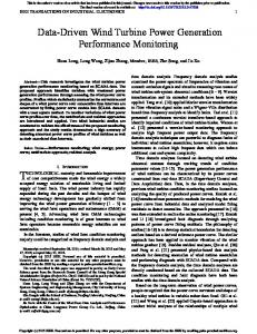
Figure 1. Physical diagram of the system
1
operation is a very simple case that can be used as a baseline. The variable-speed algorithm was chosen based on the maximum energy and steady-state limit of the wind turbine. The steady-state limit is based on the CP-TSR curve provided. Thus in the steady state calculation, wind gust and wind shear are not considered. It turns out that using the steady state limit is a good approximation in the lower wind speeds, as shown by the performance ratio and energy captured by the wind turbine. One concept that is fundamental to the control dynamics is that the speed change is relatively slow because of the large inertia involved. This makes it difficult to use the power converter to control the speed in highly variable wind applications. Pitch control is relatively fast, however, and can be better used to regulate power flow especially when near the high speed limit. Figure 1 shows the system under consideration. The wind turbine is connected to a variable-speed wind turbine. The generator output can be controlled to follow the commanded power. The wind turbine has a pitchable blade to control the aerodynamic power. The dashed line indicates that the pitch angle can be controlled. It is shown that there is a mechanical component (such as a gearbox) between the high-speed shaft and the low-speed shaft. The low-speed shaft is driven by the turbine blades, which generates aerodynamic power. The high-speed shaft is loaded by the electric generator in the form of electrical load. The paper is organized as follows: The next section is devoted to the condition of the wind data. The third section is devoted to the method of control. In the fourth section, the discussion and analysis is presented, and in the fifth section, the conclusion is presented.
TS R
=
ωm R V
(1)
where : ω m = rotor speed mechanical radian/sec R = radius of the blade meter V = linear speed of the wind meter/sec
3 Pmech = 0.5 ρ A Cp V
(2)
where: ρ = air density (kg/m3) A = swept area ( m2) Cp = coefficient of wind turbine V = wind velocity (m/s) 3
R ù 3 é P TARGET = 0.5 ρ A C p TARGET ê ú ωm ë TSR TARGET û P TARGET = K P (RPM )
(3)
3
(4)
where : P TARGET = Target power (max C p ) Cp TARGET = Cp at TSR TARGET K P = computed wind turbine data RPM = rotor _ speed
high wind speed region, the pitch angle is increased to shed some of the aerodynamic power. From Equation 1, the tip-speed ratio for a fixed speed wind turbine varies across a wide range depending on the wind speed. The power captured by the wind turbine may be written as Equation 2. From Equation 2, it is apparent that the power production from the wind turbine can be maximized if the system is
II. WIND TURBINE CHARACTERISTICS The wind turbine can be characterized by its CP TSR (curve as shown in Figure 2), where the TSR is the tip-speed ratio; that is, the ratio between the linear speed of the tip of the blade with respect to the wind speed. It is shown that the power coefficient CP varies with the tip-speed ratio. It is assumed that the wind turbine is operated at high CP values most of the time. In a fixed-frequency application, the rotor speed of the induction generator varies by a few percent (based on the slip) above the synchronous speed while the speed of the wind may vary across a wide range. In Figure 2, the change of the CP-TSR curve as the pitch angle is adjusted is also shown. In low to medium wind speeds, the pitch angle is controlled to allow the wind turbine to operate at its optimum condition. In the
Cp for different Pitch Angle
0.6
Angle = 0 deg Angle = 6 deg
Cp (Power Coefficient)
0.5
Angle = 10 deg
0.4 0.3 0.2 0.1 0 0
5
10
15
TIP-SPEED RATIO (TSR)
Figure 2. Power coefficient Cp versus tip-speed ratio
2
operated at maximum CP. As the wind speed changes, the rotor speed should be adjusted to follow the change. This is possible with a variable-speed wind turbine. Unfortunately, it appears that the wind speed cannot be reliably measured. To avoid using the wind speed, the equation to compute the target power can be rewritten by substituting the wind speed V and the CP. The target power PTARGET can be written as in Equation 3, or in it can be written in its simple form shown in Equation 4. It can be seen that the PTARGET is proportional to the cube of the rotor speed. For simulations used in this study, the wind input data is a time series of wind data of different turbulence conditions. To reduce the computing time, the input data (the wind speed) of a 10-minute time series is used. The work performed in this project was based on a generic wind turbine. The physical dimension and the CP-TSR characteristic of the wind turbine are the inputs for this program. The inertia of the blade and the inertia of the generator are given. The stiffness of the shaft and the damping are given. The induction generator modeled is a wound-rotor induction generation with the stator connected to the utility and the rotor winding connected to the power converter. The generator can be controlled to respond to the torque command almost instantaneously.
100 Aerodynamic power (kW)
B’
A
20 m/s 50
Cpmax operation
B
15 m/s
0 1000
A’
1500
2000
High speed shaft rotor speed (rpm)
Figure 3. Aerodynamic power versus rpm for two different wind speeds
speed operation is shown in Figure 4. In this figure, it is assumed that the operating CP is constant at CPmax. Pwind is the aerodynamic power that can be extracted from the wind. Pcaptured is the actual aerodynamic power captured by the wind turbine. Pelectric is the power that can be converted to electric power. When the aerodynamic power is higher than the generator power (Pelectric), the rotor rpm increases and the kinetic energy in the rotor blade increases. The rate of increase in the kinetic energy is the power difference between the aerodynamic power and the generator power, which is called Paccel and Pdecel in Figure 4. A c c e le r a tio n K in etic E n ergy
III. METHOD OF CONTROL A. Wind Turbine Power Generation The simplest wind turbine architecture is the constant rotor speed and constant pitch wind turbine. Figure 3 shows a typical aerodynamic power for two different wind speeds as the rotor revolutions per minute (rpm) is varied. As shown in Figure 3, the maximum CP operation is represented by the thick line. The wind turbine operating in a single rpm will only be optimized at a single wind speed. For example, if the wind turbine is operated at 1500 rpm, at 20 m/s wind speed, the wind turbine operates at point B’, which is not optimum power. At 15 m/s, for 1500 rpm, the wind turbine operates at point B, which is the optimum operating point. Similarly, the operation of the wind turbine at 2000 rpm is optimized only at 20 m/s, and is not optimized at 15 m/s. In variable speed operation, we must consider blade inertia. Wind turbine blades have a large inertia compared to the inertia of the generator. The inertia of the rotor behaves like an inductor in an electrical circuit. It helps smooth the rotor speed variation, and it stores energy during acceleration and restores energy during deceleration. A power flow diagram of variable-
P accel P w in d
P e l e c t r ic
P c a p tu re d
D e c e le r a tio n
K in etic E n ergy
P decel
P w in d
P e l e c t r ic
P c a p tu re d
Figure 4. Kinetic energy in the turbine at constant CP during acceleration and deceleration
3
F ig u r e 5 a : M a x C p
P c a p tu re d
P w in d
difference between the input power to the generator and the aerodynamic power captured by the wind turbine. Theoretically, at constant electric load, the acceleration and deceleration can be made zero if the pitch can be controlled fast enough to react to the wind speed such that the power captured from the wind is equal to the electric power (Pcaptured = Pelectric). For example, in the high wind speed region when the rotor speed limit is reached, the pitch can be controlled to keep the rotor rpm from exceeding its limit.
P e l e c t r ic
P C p lo ss M ax C p F ig u r e 5 b : S t a l l C p
P w in d
P c a p tu re d
P e l e c t r ic
P C p lo ss
C. Overall control strategy S ta ll C p
There are many quantities that must be considered for wind turbine generation. However, in this paper, there are two quantities considered: the electrical output power and the rotor speed. In general, the electrical output power should be smooth and non-fluctuating. This requirement is very easy to fulfill because the power converted into electrical power is controllable
Figure 5. Power flow at different power coefficients
The operation of the wind turbine along the CP TSR curves governs the power intake from the wind. The power captured by the wind turbine is affected by the operating CP on the CP -TSR curve. Figure 5 shows the operation of the wind turbine for different power coefficients. In Figure 5, only static power flow is considered. In the actual case, Pelectric must be greater than Pcaptured to dynamically force the wind turbine to stall. In Figure 5a, the wind turbine is operated at maximum CP. Thus, the aerodynamic efficiency is very high, and the power captured from the wind is optimum. The Pwind = PCaptured = Pelectric. When the wind turbine is operated in the stall condition, the power that can be captured from the wind is not optimum. The power difference between the possible power captured and the actual power captured from the wind is indicated as PCploss. The wind turbine can be forced to operate in the stall condition if the generator is loaded higher than the CPmax operation. The wind turbine will operate in the lower TSR region. This mode of operation is suitable for wind turbines that do not have pitch control capability.
F ig u r e 6 a : p it c h c o n s t a n t
K i n e ti c E n ergy ω m in cr ea ses
P w in d
P accel P e l e c t r ic
P c a p t u re d
F ig u r e 6 b : p it c h t o f e a t h e r
K i n e t i c E n e r g y n e g l i g i b le ω m con sta n t P accel P w in d
P cap tu red
P e l e c t r ic
B. Variable Pitch Wind Turbine Generation
P a e r o _ l o ss ( d u e
Variable pitch control can be used to shed the aerodynamic power generated by the wind turbine. Thus, the aerodynamic power produced by the wind turbine can be controlled by adjusting the pitch angle of the wind turbine. Figure 6 shows the effect of pitch control on power flow in wind turbine generation. With pitch control, the power captured, Pcaptured, from the wind power Pwind can be controlled by a pitch actuator. The acceleration and deceleration is the result of the
to p itc h in g
)
Figure 6. Effect of pitch control on power flow in wind turbine generation
instantly at any time (providing the generator and power converter power are below their rated values). If the
4
power is controlled to be constant, the acceleration/deceleration or rotor speed varies according to the difference between the power captured from the wind and the power generated to the utility. In this paper, the electrical power is not controlled to be constant all the time. It is controlled based on the rpm schedule as shown in Figure 7. The rotor speed can be controlled by controlling the difference between the electrical output power and the power captured aerodynamically Pcaptured. With adjustable pitch, the Pcaptured can be controlled, and with a power converter, the electrical output power can be controlled. Therefore, the rotor speed can be controlled. The ability to control the rotor speed in the high wind speed region is dependent on the pitchactuator response limit and the rating of the power converter. If the pitch actuator is too slow and the power converter size is too small, the controllability is poor. The wind turbine can be controlled to pitch-tofeather or pitch-to-stall. However, it is more common that the wind turbine is pitched to feather to reduce the aerodynamic power Pcaptured. How do we achieve zero acceleration in the rpm limit? Two ways can be used to control zero acceleration. One is to control the aerodynamic power captured by the blades (pitch to stall), and the other is to control the output power of the generator (stall the turbine by increasing the load). The capability to control aerodynamic power is limited by the pitch rate, the control algorithm, and the shape of the CP curve as a function of pitch angle.
The capability to control generator output is limited by the voltage and current rating of the generator and power converter. In general, the generator current limit related to the torque limit and the voltage limit is related to the frequency or speed limit of the generator. Lower to medium wind speed Ideally, the wind turbine should be operated at maximum CP most of the time. The control strategy used in this paper is presented in Figure 7. In the lower wind speed, when the aerodynamic power produced by the wind turbine is below the maximum power rating of the power converter, the wind turbine is operated in the CPmax. The pitch angle of the wind turbine is controlled to have the maximum possible CPmax. As the rpm changes, the pitch angle is kept at its optimum pitch angle. The electrical power is controlled by adjusting the electrical power output of the generator. The algorithm is used to control the generated power by controlling the power based on the rpm. Thus, the P(rpm) map can be used according to Equation 4. The pitch angle is generally held to achieve maximum CP -TSR curve. Higher wind speed region As the wind speed increases, the power generated by the wind turbine also increases. Once the maximum rating of the power converter is reached, the pitch angle is increased (directed to feather) to shed the aerodynamic power. As the pitch angle is increased, the wind turbine operates at lower efficiency. Figure 2 shows that the whole CP -TSR curve is shifted downward when the pitch angle is increased. With this capability, the input mechanical power driving the generator is controllable by the pitch control. Assuming the pitch control can be done instan-taneously, the acceleration and deceleration can be made zero and the speed can be kept constant by controlling the Pcaptured to be exactly equal to Pelectric. A higher pitch rate capability of a wind turbine can lessen the requirement for the generator and power converter rating. Limited pitch rate As described in the previous sections, the acceleration and deceleration can be made zero at constant electric power, provided the pitch can be controlled very fast. The rotor speed acceleration and deceleration can be described in the following simple equation:
rpmhi rpmheadroom = 10% rpmhi
dw m 1 = ò (Tcaptured − Telectric ) dt J
Figure 7. Power target versus rpm
5
dt
(5)
In Figure 8, the electrical power (Power), the captured aerodynamic power (Pmech), and the rotor rpm are shown on the same graph. The rotor is started at zero rpm and the wind turbine is motored up to cut-in speed. In this paper, no attempt was made to smooth the starting transient, thus the starting transient is beyond the scope of discussion. Consider the time of observation after the starting transients at about 10 seconds and above. As the wind speed increases, the captured power also increases. As the aero power is higher than the electrical power, the rotor acceleration is positive and the rotor speed increases. The controller follows the CPmax operating mode based on Equation 4 (i.e., the electric power is controlled to be the cube function of the rotor rpm). When the rotor rpm reaches the rpm headroom area (about 8% under maximum rpm, rpmhi), the demanded generator torque is raised to rated torque. The electrical power reflects the constant rated torque operation. Meanwhile, the blade pitch is also increased at the rate of 4 degrees per second. The aerodynamic power Pmech is still higher than the electric power, and the rotor rpm increases. At one point the Pmech is lower than the Power, which results in the rotor
The rate of rotor speed is proportional to the inverse of the inertia and difference between aerodynamic torque captured (Tcaptured) from the wind and the electric torque load (Telectric). The aerodynamic torque is affected by the operating CP and the pitch controllability. Figure 7 shows the overall control strategy. In the low-to-medium wind speed (OC), the generator is controlled in such a way that the aerodynamic torque is operated at CPmax at any rpm. In the high wind speed, there are two ways used to reduce the aerodynamic torque captured. The first one is to control the pitch, and the second one is to force the wind turbine to operate at lower CP and lower TSR (stalling mode). The second method is very suitable for wind turbines that have a limited pitch-rate capability. As shown in Figure 7, in the high wind speed region, there is an rpm, called rpm1. At rpm1, the pitch is starting to be controlled. At the same time, the generator torque is also increased to its maximum capability Trated. As the difference between Tcaptured and Telectric is positive, the rotor speed continues to increase. In this operation, Telectric = Trated which forces the wind turbine to operate in the stall mode, and the pitch is controlled to reduce operating CP significantly. It is expected that the rotor speed will eventually be controllable before the rotor speed reaches its upper limit at rpmhi. Some hysteresis is included to avoid chattering when the mode changes from one mode to another. The power profile shown in Figure 7 can be modified. For example, from point C to point B, the profile can be modified to form a slope rather than a jump as shown in Figure 7. The range of rpm between rpm1 and rpmhi is called rpm headroom. If the pitch rate can be controlled very quickly, the rpm headroom can be made small or negligible, thus rpm1 can be made equal to rpmhi. On the other hand, if the pitch rate is very slow, the rpm headroom must be made adequate to limit the rotor speed of the wind turbine. IV. ANALYSIS AND DISCUSSIONS
s
Power
Pmech
Rotor rpm
We implemented the simulation of control strategy. The rotor rpm limit rpm1 (point C) is chosen to be 34.8 rpm. The maximum power is chosen to be 750 kW. The rpm headroom is chosen to be between 10% to 20% of the maximum rpm. The pitch rate is chosen to be 4/0.7 degree/s. That is, the pitch angle can be ramped up at 4 degrees per second and it can be ramped down at 0.7 degree per second. The wind speed chosen is 14 m/s with a rough-turbulence case. The hysteresis rpm is chosen to be 2% of the maximum rpm.
rpm starting to decline. The blade pitch is controlled to decrease at about 0.7 degree per second. When the rotor power reaches the boundary of rpm headroom (about 12% under rpmhi) at about 28 seconds, the Power is returned to CPmax operating mode. The wind speed then picks up, and the Pmech increases above Power. The rotor rpm once again increases entering the rpm headroom region at about 37 seconds, and the same procedure is followed.
6
Figure 9. Wind speed, rpm, and pitch for wind turbine operation at higher pitch-rate capability
Figure 10. Power, aero-power , and power coefficient for wind turbine operation at higher pitch-rate capability
Note that the rotor rpm stays within the rpm headroom. This rpm headroom should be adjusted according to the capability of the wind turbine to control the pitch. With a high pitch-rate capability, the headroom can be made minimal. Figure 9 shows another run with different settings. In this case, the rpm headroom is minimized to zero. The rpm1 is made equal to rpmhi, and the hysteresis is eliminated. The pitch rate is changed to 8 degrees per second to ramp up and 8 degrees per second to ramp down. The result shows that the rotor speed is regulated very smoothly. The pitch angle shows a very active movement to control the rotor speed constant in the high wind speed region. The pitch angle follows the trend of the wind speed. As the wind speed increases, the average pitch angle also increases. Similarly, when the wind speed decreases, the average pitch angle also decreases. In Figure 10, the electrical power Pmech and the power coefficient CP are shown. It is shown that the power and the average Pmech track each other very closely as the wind speed changes. Although instantaneous, the difference between the Pmech and the
power is not very smooth. The fact that the inertia of the turbine blades is very high is reflected by the smooth variation of the rotor speed. The power coefficient CP shows that in the high wind speed region, the power captured can be limited by the pitch control, which will make the wind turbine operate at a very low efficiency. The operation will be reset to CPmax operating mode when the rotor speed goes under the rpmhi. In this case, as the rpm decreases, the pitch angle also decreases until it reaches the optimum setting at which the pitch angle is kept constant. Note that the electrical power is controlled to follow Equation 4 all the time. Since the rpm headroom is eliminated, there is no need to apply Trated within rpm headroom. As a result, the overall energy capture will be optimized throughout the rpm range. All of this is accomplished due to the fact that the pitch mechanism is capable of controlling the rotor rpm very fast. The overall advantage is that the energy captured from the wind can be maximized.
7
We wish to acknowledge our management at NREL and the U.S. Department of Energy (DOE) for encouraging us and approving the time and tools we needed for this project. DOE supported this work under contract number DE-AC36-98-GO10337.
V. CONCLUSIONS We simulated a pitch-controlled, variable-speed wind turbine operating in turbulent winds. We described the philosophy behind the control strategy. Slow and fast pitch rates were investigated, and their impacts were shown on the operating characteristics of the wind turbine. Considering our results, we draw the following conclusions:
•
Electrical power can be controlled instantaneously at any rpm. The only upper limit is the rating of the power converter and generator.
•
In the lower wind speed region, maximum CP operating mode is adapted. The pitch angle is kept at its optimum operation. The average CP is shown to be maximum as the wind speed varies.
•
In the higher wind speed region, the rotor speed must be controlled to avoid rotor speed increases beyond a controllable limit. The rpm headroom is defined for a low pitch-rate wind turbine.
•
•
REFERENCES [1] Muljadi, E.; Butterfield C.P.; Buhl, Jr., M. L. “Effect of Turbulence on Power Generation for Variable Speed Wind Turbines,” Presented at the ASME Wind Energy Symposium, Houston, TX, Jan. 6-9, 1997. [2] Torrey, D.; Childs S.; de Haan, S. “A VariableSpeed Wind Turbine Based on a Direct-Drive VariableReluctance Generator,” Proceedings of Windpower ’94, MN, May 10-13, 1994, Washington D.C.: American Wind Energy Association; pp. 513–522. [3] Fardoun, A.A.; Fuchs, E.F.; Carlin, P.W. “A Variable Speed, Direct Drive Transmission Wind Power Plant,” Proceedings of Windpower ’93, San Francisco, CA, July 12–16, 1993, Washington, D.C.: American Wind Energy Association; pp. 134–141.
The acceleration and deceleration can be controlled if the difference between the electrical power and aerodynamic power can be adjusted. The capability of controlling the pitch angle is very important to shed the aerodynamic power very fast. With a fast pitch rate, the rpm headroom can be minimized, and the energy captured can be optimized. With a slow pitch rate, the rpm headroom must be substantial. Additional electrical load may have to be introduced to help slow down or to stall the wind turbine. In this case, setting the electrical torque at its rated torque can be used to stall the wind turbine while the pitch angle is controlled sluggishly.
[4] Connor B.; Leithead, W.E. “Relationship of the Controllability of Power/Torque Fluctuations in the Drive-Train to the Wind Turbine Configuration.” Proceedings of the 1993 Wind Energy Conversion, Fifteenth BWEA Wind Energy Conference, October 6– 8, 1993, York, United Kingdom, British Wind Energy Association; pp. 213–219.
The smoothness of rotor-speed variation is affected by the smoothness of the power difference between electrical power and the aerodynamic power and the size of the rotor inertia. ACKNOWLEDGMENTS
We wish to thank Neil Kelley and Marshall Buhl, Jr. for providing the wind data sets used in this work, and members of the Power Systems group at NREL’s National Wind Technology Center for all the help provided during the development of this project. The authors also wish to thank the Zond engineering team, in particular Amir Mikhail and Craig Christenson, for allowing our control algorithm to be tested on their platform.
8