PixelFlow uses the technique of image composition: it distributes the ... Hardware
Architecture; 1.3,3 [Computer Graphics]: Picture/Image. Generation; 1.3.7 ...
z
Computer Graphlca, 26,2, JtJly 1992
PixelFlow:
High-Speed Rendering Using Image Composition Steven Molnar, John Eyles, John Poulton Department of Computer Science University of North Carolina Chapel Hill, NC 27599-3175
ABSTRACT
1
We describe PixelFlow, an architecture for high-speed image generation that overcomes the transformation- and frame-buffer– access bottlenecks of conventional hardware rendering architectures. PixelFlow uses the technique of image composition: it distributes the rendering task over an array of identical renderers, each of which computes a fill-screen image of a fraction of the primitives. A high-performance image-composition network composites these images in real time to produce an image of the entire scene. Image-composition architectures offer performance that scales linearly with the number of renderers; there is no fundamental limit to the maximum performance achievable using this approach. A single PixelFlow renderer rasterizes up to 1.4 million triangles per second, and an n-renderer system can rasterize at up to n times this basic rate. PixelFlow performs antialiasing by supersampling. It supports defemed shading with separate hardware shaders that operate on composite images containing intermediate pixel data. PixelFlow shaders compute complex shading algorithms and procedural and The shading rate is image-based textures in real-time. independent of scene complexity. A Pixel Flow system can be coupled to a parallel supercomputer to serve as an immediatemode graphics server, or it can maintain a display list for retainedmode rendering. The PixelFlow design has been simulated extensively at high level. Custom chip design is underway. We anticipate a working system by late 1993. CR Categories and Subject Descriptors: C. 1.2 [Processor Architectures]: Multiprocessors; C.5.4 [Computer System Implementation]: VLSI Systems; 1.3.1 [Computer Graphics]: Hardware Architecture; 1.3,3 [Computer Graphics]: Picture/Image Generation; 1.3.7 [Computer Graphics]: Three-Dimensional Graphics and Realism. Additional Keywords and Phrases: deferred shading, rendering, scalable.
antialiasing, compositing,
Permission to copy wilhout fee all or part of this material is granted provided that the copies are not madeor distributed for direct commercialadvantage,the ACM copyright notice and the title of the publication and its date appear. and notice is given,that copying is by permission of the Association for Computing Machinery. To copy otherwise, or to republish, requires a fee and/or specific permission.
01992
ACM-O-89791 -479- l/92/(U17/023 1
WI.50
INTRODUCTION
Graphics applications such as flight and vehicle simulation, computer-aided design, scientific visualization, and virtual reality demand high-quality rendering, high polygon rates, and high fi-ame rates. Existing commercial systems render at peak rates up to 2 million polygons per second (e.g., Silicon Graphics’ SkyWriter and Hewlett-Packard’s VRX). If antialiasing or realistic shading or texturing is required, however, their performance falls by an order of magnitude. To support demanding applications, future graphics systems must generate high-resolution images of datasets containing hundreds of thousands or millions of primitives, with realistic rendering techniques such as Phong shading, antialiasing, and texturing, at high frame rates (230 Hz) and with low latency, Attempts to achieve high performance levels encounter two bottlenecks: inadequate floating-point performance for geometry processing and insufficient memory bandwidth to the frame buffer [FOLE90]. For example, to render a scene with 100,000 polygons updated at 30 Hz, geometry processing requires approximately 350 million floating-point operations per second, and rastenzation requires approximately 750 million integer operations and 450 million frame-buffer accesses. 1 Parallel solutions are mandatory. Most current high-performance architectures use objectparallelism for geometry processing; they distribute primitives over a parallel array of floating-point processors, which perform transformation, clipping, and perspective division [ELLS90; MART90; SG190]. Tbe same systems use pixel-parallelism for rastenzation; framebuffer memory is divided into several interleaved partitions, each with its own rasterization processor. [AKEL88; APGA88; POTM89], This multiplies the effective frame-buffer bandwidth by the number of partitions, but does not reduce the number of primitives each processor must handle, since most primitives contribute to most partitions [FUCH79]. Because of this limitation, and the bandwidth limitations of commercial VRAMS, this approach does not scale much beyond today’s rates of a few million polygons per second. connected triangles; 3/4 of 1 Assumes 50-pixel Gouraud-shaded pixels initially visible; includes screen clear for 1280x 1024 display.
231
SIGGRAPH ’92 Chicaao, Julv 26-31, 1992
G
G
G
G
R
❑❙ ‘–biil m ,
\
G
G
G
R
R
R
8
ii
ii
\7
md!!/’L (a) Screen SuMivialon
(b) Image Compoaitlon
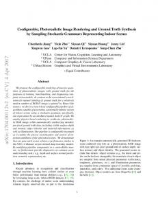
Figure 1: Rasterization methods that combine both pixel-and object-parallel rasterization (G = geometty processor, R = rasterizer, and C = pixel compositor). To achieve higher rendering performance, object-parallelism must be applied throughout the rendering process—in rasterization, as well as in geometry processing. There appear to be two ways to screen subdivision and image composition. The achieve this: two schemes are shown conceptually in Figure 1. In the screen-subdivision approach (introduced in [FUCH77] and [PARK80]), the screen is divided into disjoint regions of contiguous pixels, and a rasterization processor is provided for each region (Figure 1a). The processors simultaneously rasterize primitives that fall into different screen regions. These subimages are concatenated to form a full-screen image. Several systems of this type have been described [GARD81; GHAR88] and one built [FUCH89]. This approach is a natural advance from a simple rendering system in which a single geometry processor feeds a single rasterizer. Its main additional requirement is a global routing network to transfer primitives from geometry processors to the appropriate rasterizer. Since the mapping of primitives to rasterizers varies with the viewing transformation, every primitive in the database must be transferred over the network every frame. The network bandwidth is therefore high, and increases linearly with the rendering rate, so the approach does not scale indefinitely. A second limitation, also due to the global routing network, is the software complexity required to sort primitives by screen region and to route them to rasterizers at the appropriate time. Finally, the architecture is subject to load imbalances when primitives System performance can clump into a few screen regions. decrease significantly in this case. In the image-composition approach, rasterization processors are associated with a portion of the primitives, rather than with a portion of the screen (Figure 1b). Each rastenzer computes a tidlscreen image of its portion of the primitives, and these images are
232
composite,
based on visibility, to forma final image.
In an image-composition architecture, geometry processors and rasterizers can be paired into self-contained units, so the global routing network for primitives disappears. Instead, an imagecomposition network is required to composite output pixels from the rasterizers to form the final image. This network can be arranged as a binary tree or a pipeline; in either case, all traftlc is local. with fixed bandwidth determined bv frame rate and screen size.’ This gives the architecture its prope~ of linear scalability.2 The remainder of this paper explores the opportunities and limitations of the image-composition approach. Section 2 discusses image-composition architectures in general. Section 3 introduces PixelFlow, an image-composition architecture that achieves linearly scalable rendering performance and supports highquality rendering. Sections 4 and 5 describe its major hardware and software components. Section 6 discusses performance issues and presents simulated performance results.
2
IMAGE
COMPOSITION
ARCHITECTURES
Image composition has been used in various forms for many years, particularly in the video industry (e.g., video overlays and chroma-key) and the computer graphics community (e.g., for offline compositing of rendered images).
2A third method, closely related to image composition, is to provide separate rendering pipelines for multiple image fi-arrses. This technique, used in SGI’S SkyWriter, multiplies a system’s rendering rate and fmme rate by the number of rendering pipelines, but does not improve its latency over that of a single pipeline.
Computer
Several graphics architectures based on image composition have been proposed. Processor-per-primitive graphics systems are a simple type of image-composition architecture. [BUNK89] describes one such system, General Electric’s 1967 NASA 11 flight simulator, In the NASA II system, polygons (faces) in the database were assigned to individual processors (face cards). Each face card rendered an image of its respective face, and the results were composite using a static priority scheme. Later researchers proposed using z-values to determine the image priority at individual pixels [DEME80; FUSS82], [WEIN81 ] proposed an antialiasing scheme for a processor-per-primitive system. [DEER88] and [SCHN88] proposed deferred shading as a way to support high-quality shading in a processor-per-primitive system. [ELL19 I ] describes a processor-per-primitive system specialized for CSG rendering. which was built at Duke University and UNC. A few image-composition architectures with multi-primitive renderers have been proposed: [SHAW88] described a simplified version of Duff’s compositing algorithm [DUFF85] cast in VLSI to create a multi-renderer system that performs antialiasing. [MOLN88] proposed a simple z-buffer image-composition scheme to achieve linearly scalable rendering performance; this idea was expanded into a dissertation on image-composition architectures [MOLN9 Ib], which also describes an early version
Graphics,
26, 2, July 1992
visible at the pixel, Compositors merge packets together based on visibility and coverage information. The output of the network describes all of the surfaces contributing to each pixel, and this information is used to compute the pixel’s final color. In comparing the two approaches, the critical factors are image quality, image-composition bandwidth, and hardware complexity, Supersampling produces good results, provided that sufficient samples are taken per pixel. Unfortunately, the number of samples directly affects the bandwidth required of the imagecomposition network; however, we have produced reasonablequality images with as few as 5 samples per pixel by choosing sample locations and weights carefully [MOLN9 Ia], Only the simplest A-buffer methods are feasible in current realtime systems. These methods generally sample color and z values at pixel centers only, while calculating pixel coverage at higher resolution. This can lead to artifacts. To avoid these artifacts, additional information must be added to the surface descriptors; the result is that the two approaches require comparable bandwidth. In terms of hardware complexity, A-buffer renderers and compositors are fairly complex, while the z-depth compositors for supersampling are very simple. The A-buffer approach supports true transparency, however, which is problematic in the supersampling approach.
of the Pixel Flow architecture.
2.3 2.1
Image-composition offers two potential advantages over other architectural approaches: linear scalability and a simple programming model. An arbitrary number of renderers can be added to the system. since the image-composition network has only local traffic with fixed bandwidth determined by screen size and frame rate, Also. since renderers compute their sub-images independently, they can operate with little synchronization. This makes the parallel nature of the system largely transparent to the programmer. Image-composition architectures have several disadvantages, however. First, the image-composition network must support very high bandwidth communication between renderers. Even though the bandwidth is fixed, the network must transfer every pixel during every frame, and each pixel must include visibility information and color (and possibly even more data, if deferred shading is used), Second, pixels must be reduced to a common format for compositing, so the visibility algorithm is more restrictive than in some other approaches, Finally, up to a frame of pixel storage is required per renderer, if an entire frame is buffered before being composite; fortunately, this storage requirement can be reduced, as we will see in Section 3.
2.2
Deferred Shading
Advantages and Disadvantages
Antialiasing
Aliasing artifacts, once ubiquitous in interactive systems, are tolerated less and less each year. Future real-time systems must provide ways to reduce or eliminate these astifacts. There appear to be two ways to combat aliasing in image-composition systems: supersampling, and A-buffer algorithms [MOLN91 b]. In the supersampling approach, the image is generated and composite multiple times, once for each sample in a filter kernel. The compositors perform a simple : comparison for each subpixel; then subpixels are blended together after composition to form a final image. In the A-buffer approach, each pixel is represented by a variable-length packet describing all surfaces potentially
Image-composition architectures can take special advantage of deferred shading, a general method for reducing the calculations required for complex shading models by factoring them out of the rssterization step [DEER88; ELLS91 ]. Many shading calculations depend only on geometric and intrinsic attributes, such as surfacenormal vectors and surface color. If these attributes are calculated and stored during rasterization, shading can be deferred until the entire scene has been rasterized, and applied only to the surfaces that are visible. To defer shading in an image-composition system, rasterizers compute generic pixel attributes and composite these, rather than pixel colors. A separate hardware unit performs shading a~er pixels have been composite. In this manner, shading is performed just once per pixel, no matter how many surfaces contribute to it and how many rasterizers are in the system. Deferred shading does increase image-composition bandwidth, however, since the number of bits per pixel is generally higher. Deferred shading also separates performance concerns between the rendering and shading portions of the machine. Renderers can be built to rasterize as fast as possible, and the number of renderers can be chosen to achieve a given polygon rate. Shading performance is independent of the rastenzing performance of the system, but most be high enough to support the desired shading model.
3
PIXELFLOW
ARCHITECTURAL
OVERVIEW
PixelFlow is an experimental graphics system designed to demonstrate the advantages of image-composition architectures and to provide a research platform for real-time 3D graphics algorithms and applications. In this section we describe its major architectural features and the rationale under which they were chosen. Section 4 provides details of system components.
233
SIGGRAPH ’92 Chicaqo, JUIY26-31, 1992
Supersampling antialiasing. PixelFlow uses the supersampling approach because it is general, the compositor hardware is simple, and therefore fast, and it can be tuned to trade speed for image quality. This leads to renderers based on z-buffer raaterizem and a z-based image-composition network. Unfortunately, this requires screen-door or multi-pass algorithms to support transparency.
Plpelined image-composition network. Generating Gouraudshaded, supersampled, high-resolution images at 30 Hz frame rates requires composition-network bandwidth of at least ● 48 bits/sample ● 30 1280x 1024 pixels ● 5 samples/pixel flames/second = 9.4 Gbita/second. Deferred shading algorithms require 2 to 3 times this amount, Packaging considerations favor a pipeline image-composition network. The image-composition network can be distributed across the system by including a compositor on each board and daisy-chaining connections between boards. Logic-enhanced memory rasterizer. The renderer should a single-board design, must provide a way to scan out pixels at the bandwidth required, and should implement the compositor function at relatively low cost in board area, power, and dollars. These considerations mainly affect the design of the rasterizer. The logic-enhanced memory approach used in Pixel-Planes 5 allows a powerfid rssterizer and high-bandwidth compositor to be built in a single, compact package. In PixelFlow, we use a similar logic-enhanced memory approach. A rasterizer built with new PixelFlow enhanced-memory chips (EMCS) can render in excess of one million triangles per second and provide imagecomposition bandwidth exceeding 30 Gbitsfsecond using 64 custom memory chips and one custom controller on about 50 square inches of board area.’
Region-based rendering scheme. The compactness of this approach is obtained at the cost of introducing screen subdivision at the level of the individual renderers. As in Pixel-Planes 5, each rastcrizer contains only 128x128 pixel processors, and must generate a full-screen image in multiple steps. The advantage is that an entire screen’s worth of pixel memory is not required. Unfortunately, this implementation incurs the load-balancing problems of screen subdivision, but these difficulties are greatly reduced by providing several region’s worth of buffering within tie PixelFlow EMCS. The required image-composition bandwidth is achieved in two ways. First, the network operates bit-serially, but in parallel on 256 pixels, each with its own single-wire channel. Bit-serial zcomparison simplifies the compositors and thereby allows them to operate at high speed. Second, the network consists entirely of point-to-point communication between identical custom chips on neighboring boards, so low voltage swings and source termination can be used to save power and provide the necessary speed (132 MHz) [KNIG88]. Separate shaders for deferred shading. Deferred shading algorithms, such as Phong shading and procedural and imagebased textures, are implemented on separate hardware shaders that reside just ahead of the flame buffer. Regions of pixels, containing attributes such as intrinsic color, surface normals, and texture coordinates are rasterized on the renderers, compositcd on the image-composition network, and loaded into the shaders. Shaders operate on entire regions in parallel, to convert raw pixel attributes into final RGB values, blend multiple samples together for rmtialiasing, and forward final color values to the frame buffer.
234
Regions are assigned to shaders in round-robin fashion. The number of shaders required depends on the shading algorithm only, not on the number of primitives, since deferred shading is employed. The SIMD rasterizer used in the renderer is an ideal processor for deferred shading, since shading calculations can be performed for all pixels simultaneously. Therefore, the shaders can simply be designated renderers, with a slight enhancement of the compositor hardware on the EMC to allow bidirectional data transfers between the image-composition network and EMC memory. Shaders can be augmented with additional hardware to allow them to compute image-based textures in addition to procedural textures.
4
PIXELFLOW HARDWARE
A PixelFlow system is composed of one or more card cages, each containing up to 20 circuit boards. The backplane contains wiring for the image-composition network and clock and power distribution. The system is modular and can be configured with any number of card cages. Each board has a high-speed link connecting it to a host computer. Figure 2 shows a block diagram of a PixelFlow system.
Immediate-mode
Fast serial
‘inkr
I
PJishadm c~p”ter ‘“
,,,,,,r,feo r
I
.omma*ds
I
..... ...------\ pixel values
.A
~~
‘Boaro
.
,
●
‘ins;’~kw
(256 wires @ 132 MHz
Figure 2:
Block diagram of a PixelFlow system.
Renderers operate by sequentially processing 128x128-pixel regions of the screen. They scan out the region’s rasterized pixels over the image-composition network in synchrony with the other renderers. Shaders load pixels from the image-composition network, perform texturing and shading, blend subpixel samples, and forward pixel values to the tie buffer, The system is designed to be used in one of two basic modes 1) Immediate Mode. PixelFlow is hosted by a parallel computer, with each link connected to a separate compute node in the host. The host (e.g., an Intel Touchstone) runs an application and generates immediate-mode primitives, which are transmitted to renderers over the links. 2) Retained Mode. PixelFlow is hosted by a workstation; the high-speed links are bussed together and connected to the host via a single interface. The host distributes a display
Computer Graphics, 26,2, July
1992
Vldao Renderln Comma J s
Shsdlng Commanda ,
Renderer Board
Shader Board
4
===?+
. ...~.
~128x128-Pixei I g~ ‘ ~ SiMD Array ~ ❑ (64 EMC’S) ❑ 1? .1
1
.
.
(b)
(a)
(c)
Figure 3: Block diagrams of (a) renderer, (b) shader, and (c) frame-buffer boards. list over the renderers and loads a shading model into the shaders. On each frame, the host broadcasts editing commands and viewing parameters to the renderers, each of which then computes an image of its fraction of the dataset. Each of the primary board types (renderers, shaders, and frame buffers) includes a core consisting of a geometry processor mid a rasterizer built from the new EMC chips. These core elements have different fiction on the three board types, and shaders and tlame buffers contain additional components (Figure 3).
4.1 Image-Composition
Rssterizer. The rasterizer is a 128x128 SIMD processor array implemented with 64 PixeiFlow EMCS driven by instructions and
Network
The image-composition network is a wide (256-bit), high-speed (132 MHz) speciai-purpose communication network for rapidly moving pixei data between boards. It is distributed across the EMCS on each board, with each EMC implementing a 4-bit-wide slice (4 input pins and 4 output pins). Compositors on the EMCS synchronously transmit data unidirectionally to the compositors on the downstream board. Compositor modes. The basic unit of operation is the transfer of one 128x 128-pixel region of pixel data; the amount of data transferred per pixel is preset according to the specific algorithm. The compositors operate in one of four modes, as shown in Figure 4.
4.2 Renderer The renderer block diagram is shown in Figure 3a. components are:
Geometry processor. The geometry processor is a fast floatingpoint processor that retains a portion of a distributed dispiay list (retained mode) or receives a fraction of the primitives from the host on each frame (immediate mode). it transforms its portion of the primitives into screen coordinates, sorts them by screen region, and passes them to the rssterizer. It contains 8 MBytes of VRAM memory, serving both as main memory and as a iarge FIFO queue for buffering commands to the rasterizer. A DMA engine controls the flow of commands from the VRAMS’ serial port to the rasterizer, maintaining separate queues of commands for rasterization and for transfers over the image-composition network.
data broadcast from an Image Generation Controller (IGC) ASIC. The PixelFlow EMC (Figure 5) is similar to our previous designs [EYLE88; POUL85]. A linear expression evaluator computes values of the bilinear expression ,4x+@-t-C at every pixel processor in parailel (XY is the pixel processor’s screen iocation and A, B, and C are user-specified). Each pixel has a small local ALU that performs arithmetic and logicai operations on locai memory and on the iocai value of the bilinear expression. Operation of the pixel processors is SIMD (singie-instructionmultiple-data), and all processors operate on data items at the same address. Each pixel processor includes an enable register which qualifies writes to memory, so that a subset of the processors can be disabled for certain operations (e.g. painting a scan-converted polygon).
Its major
235
SIGGRAPH ’92 Chicago, July 26-31, 1992
A,13,C Dakinput
ALU Mlcroinstruction
Pixel
Memory Address
t
I
Load upstream pixels into memory; forward downstream.
Unload localpixels downstream,
I
Forward upstream pixelsdownstream.
EEIGZsli.
Dafs
c1
Pixel / Compositor i ..
PixelFlow EMC
4-M slice of Image ComDosifionNetwork
Figure 4: Compositor operating modes. Several features previous designs:
.
distinguish
the PixelFlow
EMC
from
our
Higher clock s~eed. The new EMC, fabricated on a 0.8Lr CMOS process: operates at 66 MHz for image-generation operations; its image-composition port transmits data at 132 MHz.
.
●
✎
✎
8-bit processors. The pixel processors, linear expression evaluator, and memory bus for each pixel are eight bits wide, rather than bit-serial. This increases the performance for many operations by nearly a factor of eight.
Fast multiply hardware. Pixel processors include hardware support for multiplies, allowing 16-bit multiplies to be performed in less than a microsecond—a total of 19 billion multiplies per second for a 128x128-pixel array. This feature accelerates multiply-intensive shading calculations. 2048+ bits per pixel. The memory design uses a Itransistor dynamic memory cell [SPEC91 ], rather than the 6-transistor static memory cell used previously. Memory per pixel can be increased to 2048 bits, plus two 256-bit communication buffers. Compositor and local-access ports. The PixelFlow EMC- contains two communication ports, one for the image-composition network, and one for communicating with texture memory or a frame buffer. Each port contains a 256-bit buffer of pixel memory that can be read or written by the pixel ALU or decoupled from it during port operation. The local-port connects to external texture memory (on a shader board) or a VRAM fi-ame store (on a frame-buffer board) through a custom datapath ASIC.
The IGC is a single custom ASIC which controls the rasterizer array. It converts floating-point A, B, and C coefficients into byteserial, fixed-point form; it sequences EMC operations by broadcasting data, control, and address information to the EMC array; and it controls the compositor ports on the EMCS.
236
Figure 5:
Block
diagram
of PixelFlow
Enhanced
Memory Chip. The lGC contains a subpixel offset register that allows the multiple samples of the supersampling filter kernel to be computed from the same set of rasterization commands, by repeatedly reading these commands from VRAM memory. This improves system performance when supersampling, since additional samples are rasterized without increasing the load on the geometry processor. As a result, a single i860XP geometry processor can keep up with the rasterizer when supersampling with 6 or more samples per pixel,
4.3 Shader The shader (Figure 3b), like the renderer, contains a geometry processor, rasterizer, and compositor. The shader’s geometry processor is merely a control processor which passes shading commands to the rastenzer. The rasterizer is used as a SIMD shading processor, computing lighting and shading models for all pixels in a region in parallel. The compositors are used to load composite regions and unload fully-shaded pixels. The local communication port of the EMCS is connected to external memory that contains image-based textures (such as Mipmaps). Multiple banks of texture memory, each holding an identical copy of the texture data, are required to match the performance of the shader to that of the image-composition network. The shader supports general table-lookup operations, so it can perform related functions such as bump mapping, environment mapping, and image warping. The shader can be loaded with an image, from which it computes a Mip-map that can then be loaded into texture memory. These algorithms will be described in a titure publication.
4,4 Frame Buffer The frame buffer (Figure 3c) closely resembles the shader, but in place of texture storage, it contains a separate double-buffered VRAM frame buffer, The ffame buffer board is itself a complete, fairly powerful, self-contained graphics system, since it also contains the core elements (geometry processor and rastenzer).
Computer Graphics, 26,2, July 1992
Tbe large amount of pixel memory on the EMCS allows several regions of pixels to be buffered before they are composite. This is important for load balancing, since different numbers of primitives may fall into a given region on different renderers (see Section 6). To take full advantage of this buffering, regions are processed in a scattered pattern, since neighboring regions tend to have similar over- or underloads; successive samples of a given region are never handled sequentially.
Function on Image Compoaltlon Network composnor modes
SampleOofregm OIScomposdad and Id~ loadedIntoshaderO L_lu L-lu* connection panem —— ——–— —— — SampleOofregion1IScompos[ted and utlklcmp C@ cmp (WI Id uuu~ loadedIntoshader1 ..— e Sample1ofregionOIScomposlted and un~ c~,pcnJpcy,p y loaded,ntoshaderO — Sample1ofreg!on1 IScompesded and wld cmp cmfrcmp W (d loadedmloshader1 uuu~ unkicmp cmpcmp
6
PERFORMANCE
The performance of a Pixel Flow system is governed by four basic parameters:
—. w
4
F[nalpixelvaluesforregionOareloaded mfoFrameBuffer(remamder ofImage compcmtlon networkISIdle)
vnkttc~,pcqp c~lp jl unld Id
Samp~e Oofragon2 IScomposlfed and loadedIntoshaderO,wh[fefinalpixelvalues forreg[on1areloadedmtoFrameMfer
Wrlddllp ~p Cyp W Id
SampleOofregion3 IScomposded and dumped!ntoshader1
.
Figure 6: Composition network operations for a 4renderer, 2-shader system computing an image with 2sample-per-pixel antialiasing.
5
SOFTWARE
PixelFlow software consists of two parts: rendering software. which transforms primitives and produces rasterizationlshading commands for the rasterizer. and control software, which sequences region-by-region operations. Both sets of software run on the geometry processor of each system board. Geometric transformations are performed using standard algorithms. and rasterization and shading are performed using the algorithms developed for Pixel-Planes 4 and 5 [FUCH85; FUCH89], The basic control algorithm to compute an image contains four steps:
2) The rastcrizer computes pixel values for all primitives in a region and for one sample of the antialiasing kernel. 3) When all renderers have finished step (2), the region is composite over the image-composition network and deposited into one of the shaders.
Transfers over the image-composition network are the only operations that require tight synchronization between boards. A hardware token chain determines when all of the boards are ready efich
transfer.
Figure
6
shows
the
sequence
Geometry processor performance. A single i860XP microprocessor can process approximately I 50,000 triangles per second, independent of the number of samples per pixel.
✎
A 64-EMC rasterizer can Rasterizer performance. process approximately 1.4 million Gouraud-shaded triangles per second and 0.8 million Phong-shaded, textured triangles per second, but this rate must be divided by the number of samples per pixel.
✎
Shader Performance. A single shader can Phong-shade and compute procedural textur~s for approximately-l 0,000 128x 128-pixel regions per second. It can compute Mipmap textures for approximately 3,700 regions per second.
The following expression can be used to estimate performance given the performance above:
system
‘v ~,,g,,,,,, = T. ~rame
~ ;=I
t?lax [
‘rOld ,’ ‘cmnP ‘ ‘shade /
1 ‘V,Yha&r.y )
where =
max( TgC>~,nli.Tra,Yri)(the rendering time for R(giotll )
TCOrrTl) =
compositing time for a region ( 1282 pixels per pixel 30 GBitslsec)
Tvhu(je
time to shade a region (approx. 270 ysec for Phong shading and texturing)
=
●
bits
If antialiasing is done, the summation is over all regions and over all antialiasing samples.
4) Steps (2) and (3) are repeated for each sample and for each rcg~on on the screen. These steps can be pipelined (i.e. one rcgionlsample is rasterized while the previous one is composite).
begin
●
T/.e,ldi
1) The geometry processor on each renderer transforms its portion of the primitives and sorts them by 128x128-pixel regions on the screen.
to
Image-Composition Network bandwidtb. Gross bandwidth = 256 bits ● 132 MHz = 33.8 GBits/sec. Net bandwidth (assuming 10°0 synchronization ovdrhead) = 30 GBits/see,
of
This equation says that the frame time is given by the sum of the times required to compute each region. and that each region time is given by the maximum of the geometry proeessin~rasterization time, image composition time, and shading time for the region. Both Tc.c)n!pand ~$hadc, are constants, for a given rendering algorithm. Tre17~ivaries depending on the number of renderers, the number of prlmltlvcs. and their distribution over the renderers and over the screen.
in a 4-renderer, 2-shader system pixel antialiasing. , ,amplc-pcr. computing an image with .-s composition
network
operations
137
SIGGRAPH ’92 Chicago, July 26-31, 1992
Tcomp provides an UPPer bound on frame rate> as shown in Fi~re 7 for several rendering algorithms and system configurations. Screen
Frame/see
16
1280x I024
22
96 (Phong)
1
1280x 1024
>100
96 (Phong)
5
1280x I024
48
192 (Phong, textured)
5
128OX1O24
24
192 (Phong, textured)
16
640X5 12
29
Bits per pixel
Samples
64 (Gouraud)
Figure 7: Peak performance network bandwidth
dictated by compositionunder varying conditions.
Actual system performance can be lower than predicted by this equation because of several factors: First, primitives may cross region boundaries and require processing in multiple regions. This increases the rasterization load by approximately 20’%. for 100-pixel polygons. Second, primitives may clump in different This increases the screen regions on different renderers. rasterization time on certain renderers relative to others. The extra buffering on the EMCS reduces this effect, but does not eliminate it entirely. For severely clumped images, system performance can be reduced from 20-60%. Finally, rasterization and compositing are pipelined, so that one region is rasterized while the previous one is composite. This requires a few idle region times at the start and end of a frame (app~oximately 5– 10% o~erhead).
Polio ( 7s) pities ( 1s Poho (P$).-
~
/.. .#-
------
Spa_c@(69)_ ... ...
Figure 8: Simulated configurations.
CONCLUSIONS
We have introduced PixelFlow, a new architecture for high-speed image generation, and one of the first to use reai-time image composition with multi-primitive renderers. Its combination of million-triangle-per-second renderers and high-performance compositing network give it linearly scalable performance to tens of millions of polygons per second— far above the performance of current systems. All of the components of PixelFlow are programmable: its geometry processors are conventional microprocessors; its rasterizers are programmable SIMD processors; its imagecomposition network is a general pixel datapath. In addition to standard rendering algorithms, such as Gouraud- and Phongshading of polygonal primitives, PixeiFlow can render primitives such as spheres, quadrics, and voiume data with high-quality shading methods, such as local light sources, procedural and image-based texturing, and environment mapping.
At the time this paper was written, logic design for the custom chips was nearly complete. We anticipate completing circuit design for the system by mid-1993 and competing a prototype system by late 1993. 4
8 16 32 Number of Renderera performance
for various
64
128
ACKNOWLEDGEMENTS system
Because these factors are scene dependent, they cannot be modelled analytically. We have written a timing simulator for PixelFlow that models these effects and have used it to compute performance for a variety of images and rendering algorithms. Figure 8 shows simulated performance for the four sample
238
7
.
L
12
These simuiated results show the behavior predicted by the equation above. System performance scales linearly with the number of renderers until a knee is reached, where compositing time dominates rasterization time (shading time is not a limiting factor for any of these datasets). The space station dataset, in particular, is very smali (3,784 primitives), so this knee is reached at only 4 renderers. Only the polio dataset is large enough to show iinear scalability to 128 renderers.
A PixelFiow system can be configured in a variety of ways. Hosted by a single workstation, it can render PHIGS-type retained-mode datasets. Coupled to a parallel supercomputer, it can serve as a visualization subsystem for immediate-mode rendering. Using PixeiFlow silicon, a million-triangie-per-second rasterizer could be built on a small circuit board.
-
,; 9/------... . / /*,: .0
databases shown in Figure 9. Simulations were run with 1 to 128 renderers and 4 shaders. Two curves are shown for each dataset: one for a supersampled image with 6 samples per pixel (6s), and one for a “fully-aliases” image with one sample per pixel (1s). For the 6s case, we assumed the geometry processor is a 66-MHz i860XP; for the is case, we assumed that a sufficiently powerful geometry processor is availabie so that renderer performance is rasterizer-iimited.
We acknowledge contributions to Anselmo Lastra, Westover, and the
the following peopie for their suggestions and this work: Henry Fuchs, Turner Whitted, Jon Leech, Brice Tebbs, Trey Greer, Lee entire Pixel-Planes team.
This research is supported in part by the Defense Advanced Research Projects Agency, DARPA ISTO Order No, 7510, and the National Science Foundation, Grant No. MIP-9000894.
Computer Graphics, 26, 2, July 1992
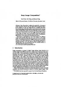
(a) Space station and space shuttle, Phongshaded, 6,549 triangles (Don Eyles, Charles Stark Draper Labs).
(b) Radiosity-shaded room interior with procedural textures, 53,514 triangles (F.P. Brooks, A. Varshney, UNC).
(c) Procedurally generated pipes model, Phong-shaded, 137,747 triangles (Lee Westover, Sun Microsystems).
(d) Poliovirus molecule, Phong-shaded, 389,819 triangles (J. Hogle, M. Chow, D. Filman, Scripps Institute).
Figure 9: Four sample datasets used for timing simulation.
REFERENCES AKEL88 Akeley, K. and T. Jermoluk, “High-Performance Polygon Rendering,” SIGGRAPH ‘88, Vol. 22, No. 4, pp. 239-246. APGA88
Apgar, B.. B. Bersack, and A. Mammen, “A Display System for the Stellar Graphics Supercomputer Model GS 1000.” SIGGRAPH ‘88, Vol. 22, No. 4, pp. 255-262.
BUNK89
Bunker, M. and R. Economy, “Evolution of GE GIG Systems,” SCSD Document, General Electric Company, Daytona Beach, FL 32015, 1989.
DEER88
Deering, M., S. Winner, B. Schediwy, C. Duffy, and N. Hunt, “The Triangle Processor and Normal Vector Shader: A VLSI System for High Performance Graphics,” SIGGRAPH ‘88, Vol. 22, No. 4, pp. 2130.
DEME80
DUFF85
Demetrescu, S., A VLSI-Based Real-Time HiddenSurface Elimination Display &stern, Master’s Thesis, Dept. of Computer Science, California Institute of Technology, 1980. Duff, T., “Compositing 3D Rendered Images,” SIGGRAPH ‘85. Vol. 19. No. 3, July 1985, pp. 414.
ELL19 I
Ellis, J., G. Kedem, T. Lyerly, D. Thielman, R. Marisa, J. Menon, H. Voelcker, “The Raycasting Engine and Ray Representation: A Technical Summary,” Proc. qfthe Intl. Jornal ofComputational Geometry and Applications, 199 I.
ELLS90
Ellsworth, D.E., H. Good, and B. Tebbs, “Distributing Display Lists on a Multicomputer,” Computer Graphics (Proceedings of the 1990 Symposium on Interactive 3D Graphics), Vol. 24, No. 2, March 1990. p.1477154.
239
SIGGRAPH ’92 Chicago, July 26-31, 1992
ELLS91
Ellsworth, D.E. “Parallel Architectures and Algorithms for Real-Time Synthesis of High-Quality images Using Deferred Shading,” Workshop on Algorithms and Parallel VLSI Architectures, Pont-aMousson, France, June 12, 1990.
EYLE88
Eyles, J., J. Austin, H. Fuchs, T. Greer, and J. Poulton, “Pixel-Planes 4: A Summary,” Adv. in Compu;er Graphics Hardware II ( 1987 Eurographics Workshop on Graphics Hardware), Eurographics Seminars, 1988, pp. 183-208.
FOLE90
Foley, J. D., A. van Dam, S.K. Feiner, and J.F. Principles and Hughes, Computer Graphics: Practice, Addison-Wesley, Reading, MA, 1990. (especially Chapter 18, “Advanced Raster Graphics Architecture”)
FUCH77
Fuchs, H., “Distributing a Visible Surface Algorithm over Multiple Processors,” Proceedings of the ACM Annual Conference, pp. 449451.
FUCH79
Fuchs, H. and B. Johnson, prepublication draft of “An Expandable Multiprocessor Architecture for Video Graphics,” Proceedings of the 6th ACM-IEEE Symposium on Computer Architecture, April, 1979, pp. 58&67.
FUCH85
Fuchs, H., J. Goldfeather, J. Hultquist, S. Spach, J. Austin, F. Brooks, J. Eyles, and J. Poulton, “Fast Spheres, Shadows, Textures, Transparencies, and Image Enhancements in Pixel-planes,” SIGGRAPH ’85, vol. 19, No. 3, pp. 1] 1-120.
FUCH89
Fuchs, H., J. Poulton, J. Eyles, T. Greer, J. Goldfeather, D. Ellsworth, S. Molnar, G. Turk, B. Tebbs, and L, Israel, “Pixel-Planes 5: A Heterogeneous Multiprocessor Graphics System Using Processor-Enhanced Memories,” SIGGRAPH ’89, vol. 23, No. 3, pp. 79–88.
FUSS82
Fussel, D. and B. D. Rathi, “A VLS1-Oriented Architecture for Real-Time Raster Display of Shaded Polygons.” Graphics Interface ’82, 1982, pp. 373380.
GARD81
Gardner, G. Y., E,P, Berlin, Jr., and B.M. Gelman, “A Real-Time Computer Image Generation System using Textured Curved Surfaces,” Proceedings of IMAGE II, 1981, pp. 59–76.
GHAR88
Gharachorloo, N., S. Gupta, E. Hokenek, P. Balasubramanian, B. Bogholtz, C. Mathieu, and C. Zoulas. “Subnanosecond Pixel Rendering with Million Transistor Chips,” S/GGRAPH 88, Vol. 22, No. 4, pp. 4149.
KNIG88
Knight, T. and A. Krimm, “A Self-Terminating LowVoltage Swing CMOS Output Driver,” IEEE Journal of Solid-State Circuits, Vol. 23, No. 2, April 1988, pp. 457464.
MART90
Martin, P., and H. Baeverstad, “TurboVRX: A HighPerformance Graphics Workstation Architecture,” Proc. of AUSGR4PH 9(?, September 1990, pp. 107117.
MOLN88
Molnar, SE., “Combining Z-buffer Engines for Higher-Speed Rendering,” Advances in Computer Graphics Hardware 111, Eurographics Seminars, 1988, pp. 171–182.
240
MOLN91 a Moinar, S. E., “Efficient Supersampling Antialiasing for High-Performance Architectures,” Technical Report TR-91 -023, Dept. of Computer Science, UNC-Chapel Hill, 1991. MOLN91b
Molnar, S. E., “Image Composition Architectures for Real-Time Image Generation,” Ph.D. dissertation, also available as UNC-Computer Science Technical Report TR91-046, 1991.
PARK80
Park, F., “Simulation and Expected Performance Analysis of Multiple Processor Z-Buffer Systems,” SIGGRAPH ’80, Vol. 14, No. 3, pp. 48-56,
POTM89
Potmesil, M., and E. Hoffert, “The Pixel Machine: A Parallel Image Computer,” S2GGRAPH ’89, Vol. 23, No. 3, pp. 69-78.
POUL85
Poulton, J,, H. Fuchs, and A. Paeth, “Pixel-planes graphic engine,” Section 9.5 in Principles of CMOS VLSI Design: A System Perspective, by Neil Weste and Kamran Eshrahian, Addison-Wesley, New York, 1985, pp. 448-480.
SG190
Silicon Graphics Computer Systems, Vision Graphics System Architecture, Mountain View, CA 940397311, February 1990.
SHAW88
Shaw, C. D., M. Green, and J. Schaeffer, “A VLSI Architecture for Image Composition,” Advances in Computer Graphics Hardware III,, Eurographics Seminars, 1988, pp. 183-199.
SPEC9 I
Speck, D., “The Mosaic Fast 5 12K Scalable CMOS DRAM,” Proceedings of the 1991 University of
California at Santa Cruz Conference on Advanced Research in VLSI, 1991, pp. 229-244. SCHN88
Schneider, B.O. and U. Claussen, “PROOF: An Architecture for Rendering in Object-Space,” Advances in Computer Graphics Hardware III, Eurographics Seminars, 1988, pp. 121-140.
WEIN81
Weinberg, R., “Parallel Processing Image Synthesis and Anti-Aliasing,” SIGGRAPH ’81, Vol. 15, No. 3, pp. 55–61