Not only have humans contributed to this work, but I am very fortunate to work with two excellent robots, Emil and Pippi. Even though you behave odd some ...
Licentiate Thesis
Plan-Based Configuration of a Group of Robots
Robert Lundh Technology
Studies from the Department of Technology at Örebro University 20 örebro 2006
Plan-Based Configuration of a Group of Robots
Studies from the Department of Technology at Örebro University 20
Robert Lundh
Plan-Based Configuration of a Group of Robots
© Robert Lundh, 2006 Title: Plan-Based Configuration of a Group of Robots ISSN: 1404-7225
Abstract Imagine the following situation. You give your favorite robot, named Pippi, the task to fetch a parcel that just arrived at your front door. While pushing the parcel back to you, she must travel through a door opening. Unfortunately, the parcel she is pushing is blocking her camera, giving her a hard time to see the door to cross. If she cannot see the door, she cannot safely push the parcel through the door opening. What would you as a human do in a similar situation? Most probably you would ask someone for help, someone to guide you through the door, as we ask for help when we need to park our car in a tight parking spot. Why not let the robots do the same? Why not let robots help each other? Luckily for Pippi, there is another robot, named Emil, vacuum cleaning the floor in the same room. Since Emil can view both Pippi and the door at the same time, he can guide Pippi through the door, enabling her to deliver the parcel to you. This work is about societies of autonomous robots in which robots can help each other by offering information-producing functionalities. A functional configuration is a way to allocate and connect functionalities among robots. In general, different configurations can be used to solve the same task, depending on the current situation. For the work on configurations, we have three steps. The first step is to formally define the idea of functional configuration. The second step is to investigate how configurations can be automatically generated and executed. The third step is to address the problem of when and how to change a configuration in response to changing conditions. In this licentiate thesis we report initial work that focus on the two first steps: the third step is a subject of future work. We propose a formal definition of functional configurations, and we propose an approach based on artificial intelligence (AI) planning techniques to automatically generate a preferred configuration for a given task, environment, and set of resources. To illustrate these ideas, we describe an experimental system where these are implemented, and show two examples in which two robots mutually help each other to accomplish tasks. In the first example they help each other to cross a door, and in the second example they carry a bar together.
i
Acknowledgements First of all, I would like to thank my supervisors Dr. Lars Karlsson and Prof. Alessandro Saffiotti at the Center of Applied Autonomous Sensor Systems (AASS), Örebro University, Sweden. Together we have had many interesting and fruitful discussions, most often research related, but the side-tracks have been entertaining. Thank you for all the support and guidance. This work was supported by the Swedish National Graduate School in Computer Science (CUGS), the Swedish Research Council (Vetenskapsrådet), and the Swedish Knowledge Foundation. I would also like to thank all the employees at AASS, especially the Ph.D. students, that help make AASS a creative and friendly work place. Not only have humans contributed to this work, but I am very fortunate to work with two excellent robots, Emil and Pippi. Even though you behave odd some times, I do appreciate the cooperation and I am looking forward to working with you in the future. Finally, my greatest love and appreciation goes to my wife Thereze and my sons, Noa and Malte. You are my never-ceasing source of happiness...
iii
Contents 1 Introduction 1.1 Objectives of this thesis . . . . . . . . . . . . . . . . . . . . . . . 1.2 Thesis Outline . . . . . . . . . . . . . . . . . . . . . . . . . . . .
1 2 4
2 Related Work 2.1 Multi-Robot Systems . . . . . . . . . . . . . 2.1.1 Degrees of Coordination in MRS . . 2.2 Approaches to Robot Team Coordination . 2.2.1 Loose Coordination . . . . . . . . . 2.2.2 Tight Coordination . . . . . . . . . . 2.3 Middle-Ware for Multi-Robot Systems . . . 2.4 Automatic configuration . . . . . . . . . . . 2.4.1 Program Supervision . . . . . . . . . 2.4.2 Automated Web Service Composition 2.5 Discussion . . . . . . . . . . . . . . . . . . .
. . . . . . . . . .
. . . . . . . . . .
. . . . . . . . . .
. . . . . . . . . .
. . . . . . . . . .
. . . . . . . . . .
. . . . . . . . . .
. . . . . . . . . .
. . . . . . . . . .
. . . . . . . . . .
. . . . . . . . . .
5 6 7 9 9 11 16 17 17 18 19
3 Functional Configurations 3.1 Preliminaries . . . . 3.2 Functionality . . . . 3.3 Resource . . . . . . . 3.4 Channel . . . . . . . 3.5 Configuration . . . . 3.6 Examples . . . . . .
. . . . . .
. . . . . .
. . . . . .
. . . . . .
. . . . . .
. . . . . .
. . . . . .
. . . . . .
. . . . . .
. . . . . .
. . . . . .
. . . . . .
23 23 23 24 25 25 26
4 Planning for Configurations 4.1 Problem Statement . . . . . . . . . . . . . . 4.2 Configuration Planning vs. Action Planning 4.3 Hierarchical Planning . . . . . . . . . . . . . 4.4 Representation . . . . . . . . . . . . . . . . 4.5 The Configuration Planner . . . . . . . . . . 4.6 Example . . . . . . . . . . . . . . . . . . . .
. . . . . .
. . . . . .
. . . . . .
. . . . . .
. . . . . .
. . . . . .
. . . . . .
. . . . . .
. . . . . .
. . . . . .
. . . . . .
29 29 30 31 31 35 36
. . . . . .
. . . . . .
. . . . . .
. . . . . .
. . . . . .
v
. . . . . .
. . . . . .
. . . . . .
. . . . . .
. . . . . .
. . . . . .
. . . . . .
vi
CONTENTS
5 Executing Configurations 5.1 Sort, Divide, and Deploy Configurations 5.2 Implementation of Basic Components . . 5.2.1 Functionality . . . . . . . . . . . 5.2.2 Channel . . . . . . . . . . . . . . 5.3 Translation of configuration description 5.4 Example . . . . . . . . . . . . . . . . . . 5.5 Monitoring the Execution . . . . . . . .
. . . . . . .
. . . . . . .
. . . . . . .
. . . . . . .
. . . . . . .
. . . . . . .
. . . . . . .
. . . . . . .
. . . . . . .
. . . . . . .
. . . . . . .
. . . . . . .
. . . . . . .
45 46 47 47 47 49 50 53
6 Experiments 6.1 The Robot Platform 6.2 Cross a Door . . . . 6.2.1 Setup . . . . 6.2.2 Execution . . 6.2.3 Summary . . 6.3 Carry a Bar . . . . . 6.3.1 Setup . . . . 6.3.2 Execution . . 6.3.3 Discussion . . 6.4 Build a Wall . . . . . 6.5 Summary . . . . . .
. . . . . . . . . . .
. . . . . . . . . . .
. . . . . . . . . . .
. . . . . . . . . . .
. . . . . . . . . . .
. . . . . . . . . . .
. . . . . . . . . . .
. . . . . . . . . . .
. . . . . . . . . . .
. . . . . . . . . . .
. . . . . . . . . . .
. . . . . . . . . . .
. . . . . . . . . . .
55 56 57 57 58 61 61 63 64 67 67 70
7 Conclusions 7.1 What has been achieved? . . . . . . . . . . . . . . . . . . . . . . 7.2 Limitations of our approach . . . . . . . . . . . . . . . . . . . . 7.3 Future Work . . . . . . . . . . . . . . . . . . . . . . . . . . . . .
75 75 76 77
A Functionality Operators and Methods A.1 Cross a Door . . . . . . . . . . . A.1.1 Sensing Resources . . . . A.1.2 Action Resources . . . . . A.1.3 Functionalities . . . . . . A.1.4 Methods . . . . . . . . . . A.2 Carry a Bar . . . . . . . . . . . . A.2.1 Sensing Resources . . . . A.2.2 Action Resources . . . . . A.2.3 Functionalities . . . . . . A.2.4 Methods . . . . . . . . . . A.3 Build a Wall . . . . . . . . . . . . A.3.1 Sensing Resources . . . . A.3.2 Action Resources . . . . . A.3.3 Functionalities . . . . . . A.3.4 Methods . . . . . . . . . .
79 79 79 79 79 80 82 82 83 83 83 86 86 86 86 86
. . . . . . . . . . .
. . . . . . . . . . .
. . . . . . . . . . .
. . . . . . . . . . .
. . . . . . . . . . .
. . . . . . . . . . .
. . . . . . . . . . .
. . . . . . . . . . .
. . . . . . . . . . . . . . .
. . . . . . . . . . .
. . . . . . . . . . . . . . .
. . . . . . . . . . .
. . . . . . . . . . . . . . .
. . . . . . . . . . .
. . . . . . . . . . . . . . .
. . . . . . . . . . . . . . .
. . . . . . . . . . . . . . .
. . . . . . . . . . . . . . .
. . . . . . . . . . . . . . .
. . . . . . . . . . . . . . .
. . . . . . . . . . . . . . .
. . . . . . . . . . . . . . .
. . . . . . . . . . . . . . .
. . . . . . . . . . . . . . .
. . . . . . . . . . . . . . .
. . . . . . . . . . . . . . .
. . . . . . . . . . . . . . .
. . . . . . . . . . . . . . .
Chapter 1
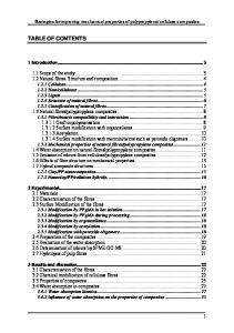
Introduction Can you help me? Is it not remarkable how we can extend our own capacity, just by asking this question? For example, by asking each other for help, we are able to address more advanced tasks then if we are alone, we can perform tasks easier, we can give each other information, and we are able to carry someone that is injured. Especially interesting are two aspects of how we help and cooperate. First, we have altruism. Humans are almost unique in the altruism of our cooperation [Fehr and Fischbacher, 2003]. We help each other even when there is no direct benefit to us, and even to people not in our family or set of acquaintances. Examples of such human altruism are to help an old lady you do not know to cross the street or to keeping a door open for a stranger. The second aspect is about tight or close cooperation. Humans and also other animals are good in solving tasks that requires constant interaction. For example, two persons can easily lift and carry a sofa together and even get guidance from a third person in narrow passages. However, this thesis is not about humans or animals helping each other. It is about robots. Robots that help each other. Is it possible for robots to do something similar to what humans do, and if so, in what situations is it necessary for robots to help each other? To answer the second question, consider the situation shown in Figure 1.1. This figure shows a mobile robot, named Pippi, that has the task to push a box through a door. In order to perform this task, Pippi needs to know the position and orientation of the door relative to itself at every time during execution. It can do so by using its sensors, e.g., a camera, to detect the edges of the door and measure their distance and bearing. While pushing the box, however, the box may be in the way of the camera. Pippi can still rely on the previously observed position, and update this position while it moves using odometry. Unfortunately, odometry will be especially unreliable during the push operation due to slippage of the wheels. There is, however, another solution: a second robot, called Emil, could observe the scene from an external point of view in
1
2
CHAPTER 1. INTRODUCTION
Figure 1.1: Can Emil help Pippi to push the box through the door?
order to compute the relative position between Pippi and the door, and communicate this information to Pippi. The above scenario illustrates that there are situations in when robots needs to cooperate in an altruistic, tightly coordinated, manner. Altruistic in the sense that Emil helps Pippi to complete her task even though it is not beneficial for him. Tightly coordinated in the sense that it is not enough that Pippi asks Emil once for the door information. She will need this information continuously because of the wheel slippage associated with the box pushing. The scenario also illustrates an instance of the general approach that we suggest in this thesis: to let robots help each-other by borrowing functionalities one another. In the above example, Pippi needs a functionality to measure the relative position and orientation of the door in order to perform its task: it has the options to either compute this information using its own sensors, or to borrow this functionality from Emil. This example of when a robot help another robot to cross a door was first presented in [Lundh et al., 2004].
1.1 Objectives of this thesis The long term objective of our work is to enable robots to help each other in an altruistic manner and especially for tasks that require tight cooperation. We consider a society of autonomous robotic systems embedded in a common environment. Each robot in the society includes a number of functionalities organized in some way, for instance, in a generic two-layer hybrid architecture as shown in Figure 1.2. In these architectures, the top layer implements higher cognitive processes for world modeling (M) and for planning and deliberation (D). The bottom layer implements sensori-motor processes for sensing and perception (P) and for motion control (C), which are connected to a set of sensors (S) and actuators (A). We do not assume that the robots are homogeneous: they may have different sensing, acting, and reasoning capacities, and some of them may be as simple as a fixed camera monitoring the environment. Thus, each robot may include several, or none, functionalities in each one of the {P, M, D, C, S, A}
1.1. OBJECTIVES OF THIS THESIS
3
Pippi
Emil
M
D
11 00 0P 1 00 11 1 0
C
S
M
D
C P S
A
A
Environment
Figure 1.2: A simple configuration consisting of two-robots: Emil is providing a missing perceptual functionality to Pippi.
classes, which it can use to perform the tasks assigned to it. The key point here is that each robot may also use functionalities from other robots in order to compensate for the ones that it is lacking, or to improve its own. In the situation shown in Figure 1.2, Pippi borrows from Emil a perceptual functionality for measuring the relative position between the door and itself. We informally call configuration any way to allocate and connect the functionalities of a distributed multi-robot system. Note that we are interested in functional software configurations, as opposed to the hardware configurations usually considered in the field of reconfigurable robotics (e.g., Fukuda and Nakagawa [1988], Mondada et al. [2004]). Often, the same task can be performed by using different configurations. For example, in our scenario, Pippi can perform its door-crossing task by connecting its own door-crossing functionality to either (1) its own perception functionality, (2) a perception functionality borrowed from Emil, or (3) a perception functionality borrowed from a camera placed over the door. Having the possibility to use different configurations to perform the same task opens the way to improve the flexibility, reliability, and adaptivity of a society of robotic agents. Ideally, we would like to automatically select, at any given moment, the best available configuration, and to change it when the situation has changed. In this context, our short term research objective is threefold: 1. To formally define the concept of functional configuration of a robot society.
4
CHAPTER 1. INTRODUCTION 2. To study how to automatically generate a configuration of a robot society for a given task, environment, and set of resources. 3. To study when and how to change this configuration in response to changes in the environment, in the tasks, or in the available resources.
In this thesis, we focus on the first two objectives above: the third objective will be the subject of future work. More specifically, we define a concept of configuration which is adequate from the purpose of automatically reasoning about configurations, and show how to use AI planning techniques to generate a configuration that solves a given task. We also describe an experimental system where these ideas are implemented, and show examples of it in which two iRobot Magellan Pro robots mutually help each-other to cross a door and to carry a bar.
1.2 Thesis Outline The remaining part of this thesis is organized as follows: Chapter 2 is a broad (but not exhaustive) survey of work related to the problems we address in this thesis. In the field of cooperative robotics, different terms are discussed, and selected approaches on robot coordination are reviewed. For the more specific problems of configuration we review robot middle-ware, and for configuration generation we review work in other domains. Chapter 3 presents the suggested framework for configurations in multi-robot systems. The main contribution of this chapter is a formal definition of configuration and its components. Chapter 4 details the approach of the automatic generation of configurations. The main contribution of this chapter is a planning algorithm that given an information goal, a domain, and a world state generates descriptions of the admissible configurations. Chapter 5 gives a detailed description how a configuration description can be translated to code executable by a group of robots. This translation includes the steps of dividing the configuration to individual configurations, deployment of configurations and the actual translation. Chapter 6 reports the results from the experiments. Three different experiments were conducted to show that our configuration framework is suitable to address tight coordination tasks. Two of these experiments were conducted on real robots. Chapter 7 concludes this thesis and presents future work.
Chapter 2
Related Work The work presented in this thesis is about robots that help each other to perform tasks. In particular, we are interested in how to setup the cooperation between robots in a group; how to automatically configure a group of robots such that they are able to perform a task that requires tight coordination. The objectives of this thesis is, as stated above, first to define a suitable notion of “configuration”, and second how to automatically generate a suitable configuration for a given task, environment, and set of resources. Hence, in this chapter we discuss: Cooperative robotics. A short introduction to the area of cooperative robotics, a brief discussion of the different aspects of cooperation, and a detailed review of the different notions of coordination of interest. (Section 2.1) Loose and tight cooperation. How have loose and tight coordination been addressed in the literature? A detailed review of interesting approaches. (Section 2.2) Robot middlewares. More specifically, robot middlewares that support concepts similar to our functional configurations. That is, robot middlewares concerned with techniques in how to program and control distributed systems such that coordination within the system easily can be obtained. (Section 2.3) Automatic generation of configuration. How is problems similar to automatic generation of configuration addressed in other domains. Here, we extend our scope to not only include research within AI and robotics, but also approaches that address similar problems in other research areas. We believe that inspiration from a broader field will yield better and more sound solutions, even thought they only address parts of our problems. (Section 2.4)
5
6
CHAPTER 2. RELATED WORK
2.1 Multi-Robot Systems The field of Multi-Robot Systems and cooperation among robots is a relatively new research area. It was not until the late 1980’s that researchers started to gain interest in issues concerning multiple physical robots. Prior to this, cooperation between agents concerned software agents and research on robots only considered single robots. In the beginning, the topics in focus was on reconfigurable robots, swarms, motion planning, and architectures. As the research area has grown, certain aspects have been more investigated then others. Several taxonomies and summaries of the field have been proposed, e.g., [Parker, 2003a, Dudek et al., 2002]. Many problems that are considered in multi-robots systems are often closely related to problems that have been or are currently address by other research areas. For example is inspiration taken from work on single robot systems. A multi-robot systems can address many single robot problems and in that way use the advantage of having several robots to solve the problems faster and more robust. Inspiration is also taken from biology where cooperation between animals (including humans) have been studied for a long time. Behaviors that have been studied are, for example, flocking [Hayes and Dormiani-Tabatabaei, 2002], foraging [Balch, 1999] and following trails [Vaughan et al., 2000]. Another large research area that considers similar problems are the multiagent and distributed artificial intelligence research areas. These areas have addressed many problems considering cooperation between agents. Early work in DAI considered distributed problem solving settings with a precedence order among sub-tasks [Durfee et al., 1988]. Later work has included the notion of coalitions between sub-groups of more closely interacting agents [Shehory and Kraus, 1998] [Lau and Zhang, 2003]. The work on coalition formation is particularly interesting. Coalition formation is concerned with the problem how to allocate tasks, that cannot be address by a single robot, to a disjoint robot teams (coalitions). The recent work by Vig and Adams [2005] points out the difficulties and potential solution how well-known coalition formation algorithms can be used for the multi-robot domain. In the multi-agent systems community, team-work [Pynadath and Tambe, 2003], capability management [Timm and Woelk] and norms [Boella, 2003] have also been used to account for the different forms of interactions between the sub-tasks performed by the agents in a team. For a more detailed overview of research on multi-agent coordination, see the article by Pynadath and Tambe [2002]. For more general overviews in the area of agents and multiagent systems, see [Lesser, 1999, Nwana and Ndumu, 1999, Jennings et al., 1998, Sycara, 1998]. Our approach is mainly concerned with the problems of coordination among physical robots. The next section gives a more detailed description of the related work in this area.
2.1. MULTI-ROBOT SYSTEMS
2.1.1
7
Degrees of Coordination in MRS
How can a robot team accomplish a task, and who should perform which part of the task? This is what coordination among robots in a team is all about; to organize robots to act smoothly together. Coordination can be seen as the mechanisms that facilitates cooperation between robots. There are many aspects of this problem, for example, how should the coordination be organized, who should organize it, how much coordination is required to perform this task, etc? For the aspects concerned with organization, the range of system architectures are from centralized to distributed. In a highly centralized system, one single organizer is taking decisions for all parts of the system. In the extreme case, a group of robots controlled by a single leader robot can be viewed as one single robot with remote sensors and actuators. The most obvious drawback with such a system is that it has one single point of failure: if the central organizer fails, the whole system fails. Another common drawback is that a centralized system is reacting slower to changes that affect the system. On the positive side, it is easier to find optimal plans for a centralized system. In a fully distributed system, the robots are more independent and the decisions are taken jointly through negotiation. This approach is more robust since there is no single point of failure. On the negative side, it is harder to find optimal solutions and the negotiation process is usually quite consuming in terms of communication resources. For more details on organization of coordination we refer to the article by Farinelli et al. [2004] and the article by Dias and Stentz [2003]. Another aspect of coordination is the amount or degree of coordination between robots. Examples of terms used in the literature to describe the degree of coordination are tight coordination, tightly-coupled cooperation, multi-robot task and strong coordination versus loose coordination, loosely-coupled cooperation, single-robot task and weak coordination. Strong coordination is defined by Farinelli et al. [2004] as coordination that relies on a coordination protocol. Weak coordination is then coordination that does not rely on a coordination protocol. A coordination protocol is a way for the robots to be aware of other robots actions in the team and is usually defined as a set of rules that specifies how robots interact with each other. Tight and tightly-coupled refers to when the amount of coordination is high, loose and loosely-coupled refers to when the amount of coordination is low. Since high and low are vague concepts that are hard to define, several definitions in the literature also uses the task perspective to get more crisp. Kalra et al. [2004] refers to a spectrum of tasks that requires different amount of coordination in the team of robots. The teams can be either loosely coordinated, moderately coordinated, or tightly coordinated. Loosely coordinated teams are able to address tasks that are easily decomposable into individual subtasks that can be executed by a single robot. When decomposition and
8
CHAPTER 2. RELATED WORK
allocation is achieved, no coordination is required. Moderately coordinated teams are able to address tasks that are decomposable into individual subtask with timing constraints between the subtasks. Coordination is required for the decomposition and allocation to meet the timing constraints. Robots also need to coordinate to start the execution of the subtasks correctly, but during the actual execution of the subtask, coordination is not required. Tight coordination teams are able to address tasks that are difficult or even impossible to breakdown into subtasks executable by individual robots. Such tasks requires that the team members work closely together both during the planning and execution of tasks. Single- and multi-robot tasks also refers to the task. Gerkey and Matari´c [2003, 2004] presents an extensive taxonomy for coordination and defines a single-robot task (SR) as a task requires exactly one robot to achieve it and a multi-robot (MR) task as a task that can require multiple robots. Further, they define a robot to be single-task (ST) when it only can address one task at a time and multi-task (MT) when it can address several tasks at a time. We will not try to define tight and loose coordination in this thesis, but rather clarify our interpretation of the existing ones. The definitions in the literature are usually concerned with whether a task can be accomplished by a single robot are not, i.e., loose coordination refers to tasks that can be accomplished by a single robot and tight coordination refers to task were several robots are required. We believe that the problem with these definitions is that robots, as well as humans, have different abilities. A well equipped robot with a large range of abilities may be able to solve a task that is considered to require tight coordination on its own. A group of less equipped robots may need tight coordination in order to solve a task that is expected to be solvable by a single robot. This means that a task that is defined as a tight coordination task by some researchers can be considered as a loose coordination task by others. For example, the task of going through a door would clearly be a loose coordination task in most cases. But what if the robot is sensor-poor, and needs assistance in order to cross the door. Is it still a loose coordination task? We choose to use the following interpretation of loose and tight coordination approaches: Loose coordination approaches consider tasks that can be divided into independent subtasks. The robots interact extensively to divide and distribute the subtasks among each other. During the execution of the subtasks, the robots interact very little since the subtasks are to be considered independent of each other. Tight coordination approaches consider tasks that cannot be divided into independent subtasks without problem. The robots must interact extensively to decide who should do what part, but also during the actual execution.
2.2. APPROACHES TO ROBOT TEAM COORDINATION
9
It is not always easy to distinguish if a task requires loose or tight coordination, and a loose coordination task can easily become a tight coordination task if the capabilities of the robots change. Therefore it is important to keep in mind that the amount of coordination required for a task is not only dependent on the task, but also on how “capable” the robots are that performs the task. Consider a group of robots that gets the task to vacuum-clean every room at a floor in a hotel. All robots are capable of localizing, avoiding obstacles, and of course vacuum-cleaning by themselves. For this task, the robots must interact extensively when they decide who should clean which room. However, during the actual cleaning very little interaction between robots is required. Hence, for the above conditions, the task can be considered a loose coordination task. As an example of more demanding task in terms of coordination, consider a group of two robots that gets the task to move a sofa from a room on floor one to a room on floor two in the same hotel. The robots have the same capabilities as the robots that vacuum-cleans, except that instead of being able to vacuumclean, they have the capability to lift and carry things. Thought, in order to lift and carry as large things as sofas, each robot needs to cooperate with at least one other robot. For this task, the robots needs to interact extensively during the entire duration of the task. Both during the decision of who should carry which end of the sofa, but also the actual moving process requires to be done in a coordinated fashion. This to avoid to drop the sofa or bumping in to things. Here it also important to note that coordination does not imply explicit communication as in sending messages to each other. While carrying a sofa, the robots can coordinate implicitly through the sofa. If one robot slows down, the other robot can feel this through the object they both carry. A task of this complexity with the mentioned robots could be considered a tight coordination task. For the question if a door crossing task is a loose coordination task if the robot that are about to cross the door is not capable of “sensing” the door. For these conditions, the answer is no. To cross the door safely, the robot needs guidance continuously from another robot (or agent) that is able to obtain the information required. Thus, the coordination must be tight.
2.2 Approaches to Robot Team Coordination 2.2.1
Loose Coordination
Since the primitives in loose coordination are single robot tasks, the main problem is how to allocate the tasks, rather then how to perform them. This problem is usually referred to as task allocation, or role assignment when the primitives are roles. Task Allocation is concerned with the problem of how to allocate a number of tasks to a number of agents taking into account that different agents may be differently adequate for different tasks. The simplest case, when a task only
10
CHAPTER 2. RELATED WORK
can be assigned to one agent and an agent only can be assigned one task, is also known as an Optimal Assignment Problem [Gale, 1960] and have been studied in Game Theory and in Operations Research since 1960. In the research area of cooperating robots, multi-robot task allocation is one of the more mature topics, and a great amount of approaches have been proposed. Here, the problem can be formulated as follows: There are a number of robots, each looking for a task, and a number of task, each requiring one robot. Tasks can be of different importance, meaning that tasks get priorities according to how important it is that the task is accomplished. The robots have different capabilities in terms of accomplishing different tasks, i.e., each robot estimates its capability to perform each potential task. The main problem is to maximize the overall expected performance for the assignment of tasks to robots, taking into account the priority of tasks and the different capabilities of the robots.[Gerkey and Matari´c, 2003] A great majority of the proposed approaches are based on the Contract Net Protocol (CNP) [Davis and Smith, 1983]. CNP uses auctions in order to assign tasks, i.e., robots make bids on available tasks using their task-specific performance estimation. The robot that is best suited to perform the task will get a contract for the task, since his/hers performance estimate will win the bid. The contract allows the robot to execute the task. Some examples of approaches that uses some variant of the CNP are M+ [Botelho and Alami, 1999], Murdoch [Gerkey and Matari´c, 2002], TraderBots [Dias and Stentz, 2001], GOFER [Caloud et al., 1990]. Another well-known architecture, not based on the CNP, is the behaviorbased ALLIANCE architecture [Parker, 1998b]. This architecture uses a greedy algorithm to find the best task allocation. The algorithm consist of four, very simple steps: (1) find the pair of task and robot that gives highest utility, (2) allocate this task to that robot, (3) remove this task-robot pair from the list, and (4) if the list is empty, stop, otherwise go to step (1). ALLIANCE also has an interesting solution to the problem of when to reassign tasks. The architecture use something called motivational behaviors that are based on two internal models for impatience and acquiescence. Impatience allows robots to take over tasks from other robots in the team. If robot A gets the impression that robot B is not able to accomplish its assigned task, robot A gets impatient and can take over the task from robot B. Acquiescence works in a similar way by allowing a robot to give up its current task if the progress is not sufficient. The use of internal models make the approach very efficient in terms of communication overload, compared to other approaches where robots broadcast their utilities (e.g. [Werger and Matari´c, 2000]). For a more detailed overview and analysis of current research in multi-robot task allocation see the articles by Gerkey and Matari´c [2003, 2004].
2.2. APPROACHES TO ROBOT TEAM COORDINATION
11
As mentioned above, role assignment considers the same problem as task allocation but with roles as primitives. A role is usually defined as a set of available actions, e.g., a football player with the role DEFENDER have the available actions to pass the own goalie, make a sliding tackle, etc, but the action to catch ball with hands is not available. Examples of different approaches that consider role assignment are [Vail and Veloso, 2003, Stone and Veloso, 1999, Frias-Martinez et al., 2004]. Mentioned approaches to multi-robot task allocation assumes that the tasks to allocate are primitives, i.e., tasks that can be executed by a single robot with the right capabilities. They do not consider tasks that requires tight coordination between robots.
2.2.2
Tight Coordination
In oppose to loose coordination, the focus for research on tight coordination tasks have mainly been on domain specific approaches, and not on how to perform or allocate the task in a more generic sense. The obvious reason for this is that the primitives are not single robot tasks, but rather tasks with several interacting robots involved. Compared to loose coordination where the coordination is only in the initial phase, when the task is decomposed and allocated, tight coordination also requires that the robots coordinate (extensively) throughout the entire duration of the task. This means that a general approach for tight coordination in addition to the question “Who should do what?” needs to answer the question “How should we perform the task?”. These questions are not easy to answer since the tasks often requires realtime coordinated control between robots for execution and the robots must act in a highly coordinated fashion in order to complete them. Thus, the main part of the previous work has been on solving the tight coordination problem for a specific domain or task. An example of such a domain is formation control [Saffiotti et al., 2000], which considers the problem of keeping and changing formations of robots. For this domain, a mechanism for multiple objectives is of great importance. Here, a robot has at least two objectives that need to be considered: the team objective (to keep the formation) and the individual objective (to avoid obstacles). Object transportation and cooperative manipulation[Rus et al., 1995, Stroupe et al., 2005] are other domains that typically requires tight coordination among robots. A great variety of approaches that consider these problems have been proposed. Apart from the common approaches with robots pushing1 or carrying boxes, there exist more peculiar approaches with robots transporting boxes using ropes [Donald et al., 2000]. Even though these tasks require tight coordination between robots, the amount of planning for such a task is rather low. For example, while carrying or pushing objects, robots can 1 Some researches argue that box-pushing tasks are not to be considered as tight coordination tasks since a single robot can push one end at a time. This is true for some cases, but as we stated before, this depends on the involved robot capabilities
12
CHAPTER 2. RELATED WORK
work in a leader-follower manner and in a rather simple way adopt a tightly coordinated behavior. However, for more complex tasks, more interaction and planning of interaction is required. As these domain specific approaches are reaching an acceptable level, attempts to more general approaches for tight coordination are proposed, i.e., approaches that address the problem of how to perform a task and/or who should do which part of the task. In the two following subsections, we will focus on approaches that tries to answer these question in a more generic way. Who should do what? For the question of who should do which part of a task, there are some work in progress to extend traditional multi-robot task allocation to incorporate tight coordination tasks. The Robotics Institute at Carnegie Mellon University is a research group that address several different subareas in cooperative robotics. In this group there are three directions that are particularly interesting to us. The first direction is on task allocation for complex tasks, the second on task allocation for tight coordination, and the third is on an architecture for tight coordination. Common for all three directions is that the work is based on the market based approach called TraderBots [Dias and Stentz, 2001] that uses the Contract Net Protocol mentioned in Section 2.2.1. Further, we present the different directions. The work by Zlot and Stentz [2005] focus on task allocation for complex tasks. They define complex and simple tasks as follows: Complex Tasks are tasks that may have many potential solution strategies; finding a plan to a complex task often implies solving an NP-hard problem. Simple Tasks can be executed by a robot in a straightforward, prescriptive manner. In the definition of complex tasks, complex should be interpreted as its true meaning, i.e., consisting of interconnected parts. The complexity in the task lies in the relation between subtasks. The relations can be in terms of boolean logical associations (e.g. or represents alternative solutions) or precedence constraints. This does not necessarily imply tight coordination between robots, hence the relation between tasks may only require that one task should be finished before an other tasks starts, such a constraint can be fulfilled using loose coordination. As mentioned earlier, the approach presented for this problem is market based. In market based approaches for traditional Multi-Robot Task Allocation, robots are making bids on tasks that are put up for auction. The robot that is best suited, or rather, believe that it is best suited will win the bid and the right to perform the task. For complex tasks, the auction is different. A complex task cannot be neatly divided between robots, hence to put up a
2.2. APPROACHES TO ROBOT TEAM COORDINATION
13
single task for auction does not make any sense. Instead, task trees are put up for auctions. A task tree is a way to represent the different relations between subtasks with the abstract tasks as rotes and primitive tasks as leafs. Relations are represented as different types of edges. By having task tree markets, the approach enables robots to express their valuations for both plans and tasks. This is not possible for other approaches that assume that complex tasks are decomposed into primitive subtasks before the allocation step. Complex tasks and the approach presented is not directly focused on tight coordination, rather a complementary direction that can incorporate tight coordination. The second direction is focused on a market based task allocation that incorporates tasks that requires tight coordination. The approach is presented by Kalra et al. [2004, 2005] and is called Hoplites after the ancient Greek infantrymen who specialized in tightly-coordinated maneuvers. The Hoplites framework especially address tasks that requires extensive planning of future interaction between robots in a team. An example of such a task is gallery monitoring. A gallery with several wings must be kept “secure”. The level of security is different for different wings which means that some wings are constantly observed and some wings are watched more periodically. The proposed framework uses a market based approach where each robot is rewarded when a task is completed. The size of the reward is based on how much closer it brings the group to accomplish the team goal. The market incorporates both passive and active coordination. Passive coordination is used for easier problems and works in a more robot local fashion where they react to each others actions implicitly. Active coordination addresses harder problems and coordination is achieved explicitly by selling and bidding on complex plans on the market. In the architecture, robots use passive coordination as long it is profitable, i.e., until it discovers that active coordination would result in a more profitable solution. The framework does not include a specific planner for generating team plans. The planner to use is chosen dependent on the domain in which the robots should operate. The two directions presented above are work in progress and efforts have recently been made [Stentz et al., 2004] to merge them into the TraderBot architecture. The third direction, Simmons et al. [2000, 2002] presents a three-layered architecture for coordination of heterogeneous robots. The robots coordinate by allowing the three layers to interact with their similar layers located at different robots. For example, at the planning layer, the allocation of task uses the same market based approach as the other directions to coordinate the planning. The work consider a task involving a heterogeneous team of robots — a crane, a robot with a manipulator, and a robot with stereo cameras — solving a construction task where a beam is placed on top of a stanchion. This task requires tight coordination between the robots involved; the robot with the stereo camera tracks the scene and sends information about the position differences to foreman that controlls the movement of the crane and the robot with the
14
CHAPTER 2. RELATED WORK
manipulator. In the real experiment, the configuration of the team, including the setup of information flow, is hand-coded. However, in their motivating example, it appears that an objective of this work is to develop techniques that enables robots to assist each other with information or capabilities in tightlycoupled tasks automatically. Unlike the other two directions this work does not seam to be active any more. On the work on roles, Chaimowicz et al. [2004] at University of Pennsylvania, presents an approach using dynamic role assignment. In this work, they define a role as “a function that one or more robots perform during the execution of a cooperative task”. Such a role determine how the robots act in terms of actions and interaction with each other. The basic concept of the architecture is that at all time there is at least one leader and one follower. The leader broadcasts its own estimated position and velocity to all the followers. The planner on the leader and the trajectory controllers on the followers send set points to the controller. Each robot possesses a cooperation module that is responsible for the role assignment (leader/follower) and for other decisions that directly affect the planner and trajectory controllers. It is important that the best suited robot (in terms of sensor power, manipulation capabilities) leads the group. The leadership is changed either by the leader relinquishing it to another robot or by a leadership request from one of the followers. The experimental validation shows three different experiments with robots that carries a box. The limitation of this approach is the scope of tasks that it can address. The approach requires that the task is some type of transportation or formation task. How to perform a task? For the question “how to perform a task?”, interesting work is presented by the Distributed Intelligence Laboratory, headed by Lynne E. Parker, at University of Tennessee. Already in the late 90’s, Lynne Parker2 presented an idea of how to automatically synthesize cooperative mobile robot teams[Parker, 1998a]. In this paper, the following question is in focus:“Given a pool of heterogeneous robots and a mission to be accomplished, what is the proper composition of robots for a team, and what strategy of cooperation and interaction should they use?” The question can be extended to also include how to optimally form the team, in terms of cost, fault tolerance, efficiency, interference, individual robot complexity, team size, etc. The main point however, is that this question should be addressed by an automatic design system, and not by researches at it is today. Parkers approach uses the notion of information invariants presented by [Donald, 1995]. The idea with information invariants is that to perform a task, certain information is required. This information can be obtained in several different ways, using different sensors and/or different sensory computational systems. Independently of the way the information is obtained, the re2 At
that time, at the Oak Ridge National Laboratory
2.2. APPROACHES TO ROBOT TEAM COORDINATION
15
quirements on this information stays the same, i.e., the information is intrinsic. This intrinsic information is termed an information invariant, which measures the complexity of the information required to perform a task. To address a given mission, the approach proposed by Parker uses the following methodology. The first step is to extract the information invariants and map them into equivalent classes of robot teams that are able to solve the mission. These equivalent classes defines the different components (e.g. sensors, actuators, behaviors, etc) of the robot team that is required for that particular mission. The next step is to select the most effective team components that meets requirements by the information invariants of the mission. In the proposed implementation, the cost function used for optimal selection is utilized by simply counting the number of modules. The combination that meets the requirements and uses the least number of modules is chosen. The final step involves distributing the components over the team of robots. To optimize this step, the mission metrics are used. This early work by Parker, to use the idea of information invariants in the work of automatically synthesize a team composition based on application requirements, is interesting. However, no progression on the work were reported, until 2003. The work by Parker [2003b], and Parker et al. [2004] address tight coordination tasks required to build a sensor network with a large number of robots (originally 100+, later 70+). The team consist of members with different sensor capabilities, from simple sensor-poor robots to sensor-rich leader robots. The tight coordination tasks in focus, address the deployment of simple robots by leader robots. First, several simple robots follows a leader to their destinations (Long-Distance-Navigation). In the final part of the deployment process, simple robots are teleoperated by leader robots. When the simple robots are deployed in the area, they are working as an acoustic sensor network for detecting intruders. In this article, Parker et al. (again) state the objective to develop techniques that enables robots to assist each other with information or capabilities in tightly-coupled tasks automatically. Though, in the presented approach, the team configuration is hand-coded. As a continuation of the project with 70 or more robots, the group started to work on autonomous sensor-sharing for tightly-coupled cooperative tasks Parker et al. [2005], Tang and Parker [2005b,a]. The approach presented in this article is called ASyMTRe (Automated Synthesis of Multi-robot Task solutions through software Reconfiguration, pronounced Asymmetry). As above, this work is inspired by Information Invariants [Donald, 1995], but also by the work on Schema Theory [Arkin, 1987]. As in Schema Theory, each robot consists of a number of building blocks or schemas that can be categorized into the following groups: environmental sensors, perceptual schemas, motor schemas, and communication schemas. By connecting the different schemas to each other in the correct way, the information required by a task can be retrieved through an information flow that reaches from environmental sensors to motor schemas. The principle with ASyMTRe is to connect the different
16
CHAPTER 2. RELATED WORK
schemas in such a way that a robot team is able to solve tightly-coupled tasks by information sharing. This is done automatically using a greedy algorithm that starts with handling the information needs for the less capable robots and continues in order to the most capable robots. For each robot that is handled, the algorithm tries to find the robots with least sensing capabilities and maximal utility to provide information. In the original approach the algorithm was centralized. However, recently this approach have been demonstrated with a distributed solution [Tang and Parker, 2005c].
2.3 Middle-Ware for Multi-Robot Systems In this section, we will address different frameworks that aims to facilitates the control of distributed systems, in particular multi-robot systems. This incorporate techniques on how to program and coordinate a distributed system. Simmons and Apfelbaum [1998] presents an imperative language, TDL (task description language) which is a superset of C++, for specifying tasks. The idea with TDL is to simplify the task-level control of robot programming. Task-level control refers to the robot capabilities such as, deliberation and reactivity, recovery from exceptions, and resource management. TDL supports task decomposition, synchronization of subtasks, execution monitoring, and exception handling, to meet the requirements that such robot capabilities demands. The language, originally designed for single robot use, have been extended to facilitate task-level coordination between robot, as well as the possibility for robots to spawn or terminate tasks on each other. TDL is used in [Simmons et al., 2000] reported above. Chaimowicz et al. [2003] presents a framework, ROCI, for composing task out of self-contained, reusable modules. A module contains a process which take data as input, process the data, and present its resulting data as output. The ROCI (Remote Objects Control Interface) framework is used to facilitate the development of robotic applications for MRS. The ROCI architecture consist of several different components: kernel, database, network, module, task, browser, etc. The ROCI kernel is the key component that manages the network, the database of nodes and services, and the module and task allocation process in the system. The ROCI modules mentioned above are combined into tasks. The modules are connected with pins. Data from modules or tasks can be subscribed by other modules. The ROCI browser is used to present information about the network to a human user. The framework is demonstrated with two different examples: an obstacle avoidance task for a single robot and a localization task for a group of robots. The Method of Dynamic Teams [Jennings and Kirkwood-Watts, 1998] is a framework for robot programming that tries to enable more creative, powerful and efficient solutions to many tasks. The desired type of agent organization should be derived from the task description, since different tasks require different types of organization. The task solution can be designed by a user, by
2.4. AUTOMATIC CONFIGURATION
17
a planning system, or by another agent. They want small robots to cooperate in order to solve tasks that is too difficult for a single robot or to solve the task more efficiently than a single robot. To do so, the robots form dynamics teams that can grow, shrink and change members automatically. The method is demonstrated with a search and rescue task. The search part use loose coordination and the rescue part use tight coordination. Alur et al. [2002] presents a software framework for development of controllers and estimators for multi-robot coordination. The software enables the developer to reprogram the behaviors of the team at run-time, in order to adapt to new tasks. The approaches presented in this section are frameworks that makes it easier for a human operator to configure robots to specific tasks. In contrast, the work proposed in this thesis uses the framework to automatically generate configurations that can be executed by robots.
2.4 Automatic configuration Automatic configuration is concerned with the problem of how to (automatically) set up the components in a configuration such that it meets the requirements of a specific problem. So far, the focus of this chapter have been on approaches implemented on physical robots, but there is a large amount of related work that address similar problems that consider other application, both within Artificial Intelligence, but also in other areas. Areas that address similar problems are the areas of program supervision and web service composition. In these areas, traditional AI planning techniques are used to generate configurations automatically.
2.4.1
Program Supervision
Program supervision is concerned with the problem of automating the reuse of complex software. A typical program supervision system consist of: • a database for organizing a library of programs, • a knowledge base that describes the different programs in the database, • a user interface that enables users to put up requests on the system and for an expert to modify the system, and • a supervision engine that select, plan and execute the programs based on the information in the knowledge base and the information given from the user. In such a system (Figure 2.1), the user gives a request of the output data in interest, together with input data. The program supervision engine uses this data to generate a plan of programs that can produce the requested output
18
CHAPTER 2. RELATED WORK
Figure 2.1: A simplified model of a program supervision system
data. In order to do this it uses the information in the knowledge base that describes the characteristics of the programs in the database. An expert of the domain, that the program supervision tool will address, can/must provide the system with the appropriate information. The most interesting part for us is the supervision engine that must generate a plan of programs that can produce the requested output. This is similar to the problem of generating configurations. In program supervision, hierarchical planning techniques have been extensively used with good results. Program supervision have been used in a number of different areas, for example in signal processing [Klassner et al., 1998], scientific computing and software engineering. However, the term program supervision is mainly used in image processing. An examples of an application in the image processing area are detection of objects in road scenes [Thonnat et al., 1994]. There have also been work on program supervision for robot applications. Morisset et al. [2004] presents a supervision system for a single robot that is able to learn how to perform high level tasks. The system generates modalities, using a hierarchical planner, that consists of a combination of sensory-motor functions. By combining these in to modalities, the robustness of the system improves. An MDP is used to determine which modality is appropriate for a particular situation.
2.4.2
Automated Web Service Composition
A research area that more recently have gained a lot of interest is the semantic web. “The Semantic Web is an extension of the current web in which information is given well-defined meaning, better enabling computers and people to work in cooperation”[Berners-Lee et al., 2001]. Here, the problem of how to automatically put together different web services (web service composition) to get new services is particularly interesting. Consider the following problem: you want to go to Rome for a weekend. At first, this does not really look like
2.5. DISCUSSION
19
Figure 2.2: A framework for service composition systems [Rao and Su, 2004].
a problem, hence going to Rome is probably nice. However, to plan a trip with different transportation (car, train, flight, etc) and occupation (Hotel, hostel) is difficult, even thought there are web services that handle each of them separately. The example is a simplified version of the example given in [Koehler and Srivastava, 2003]. For the example above, the web service composition problem would be to combine the different services such that they together form a service for booking trips. The automated web service composition is then when a composition must be generated automatically based on a user request. The article by Rao and Su [2004] presents a framework for automated web service composition that highlights the different parts that is necessary for a service composition system. Figure 2.2 shows an illustration of the model. This model is similar to the model for program supervision. Both models have two types of users, one that sends requests to the system and one that provides the information with the appropriate knowledge services. Both are systems with databases that handle the services or programs and a module that automatically generates the configurations. However, the framework for automatic web service composition also includes modules for translation between specifications, an evaluator and an execution engine. The translator is used to translate between a more easy straight forward language used by users and the specification language used by the system. The evaluator is used to evaluate the solutions by the automatic generator so that the best solution is selected. The execution engine executes the composite service. As for program supervision, approaches based on planning are widely used to automatically compose web services. The article by Peer [2005] gives a detailed description of the different AI planning techniques used for the problem.
2.5 Discussion In this chapter we have given an overview of different research that in some way are related to the problems we address in this thesis. First, in Section 2.1 we discussed different notions of cooperation and coordination. This since we
20
CHAPTER 2. RELATED WORK
want to address problems concerned with several robots working together. For work on coordination, we looked even further in to existing work in the field of loose and tight coordination in Section 2.2. We are particularly interested in work on tight coordination, and how the question: “How to perform a task?” can be answered. One way to approach this question is to automatically setup the coordination of the robots; to configure the robots interaction and performance such that they know how to perform it. We address this question in two steps. First, to find a suitable notion of a configuration. In Section 2.3 we reviewed research on robot middle-ware. Here, the focus is mainly to have a good representation of robots, their capabilities, and communication channels to enable human users to easily configure a team of robots for a specific mission. The second step of our approach is to automatically generate configurations for a given task, environment, and set of resources. For this problem, we examined how work on “automatic configuration” is addressed in other domains. From the work presented in Section 2.4, it is clear that techniques inspired by planning has a dominating role in the approaches suggested to this problem. In Section 2.2.2, we reviewed the work on an approach called ASyMTRe. Among the approaches presented in this related work, the work on ASyMTRe has most in common with the work presented in this thesis. Both works address the question of “How to perform a task?”, and the different notions and methods share many similarities. Even thought there are similarities, the approaches differs on several important points. First, the ASyMTRe approach aims to generate an optimal configuration for a team of robot. The configuration shall fulfill the helping needs of all robots. At can be seen as the configuration is generated at a level above the individual robots; a higher level that is telling who should help whom and how. The goal of our approach is not to fulfill all the needs of all robots in one configuration. Our approach is more at that individual robot level. When a robot is assigned a task, it will generate a configuration that helps it to perform the task. This configuration my include other robots that provides valuable information but it may also only include the robot that got the task. In this way, each robot that gets a task is responsible on its own to generate a configuration that gathers the help it needs. Second, the method to generate configurations are not the same. ASyMTRe uses a greedy algorithm that starts with handling the information needs for the less capable robots and continues in order to the most capable robots. For each robot that is handled, the algorithm tries to find the robots with least sensing capabilities and maximal utility to provide information. In contrast to the ASyMTRe approach, the approach presented in this thesis uses a hierarchical planner to automatically generate configurations. We expect that the use of a hierarchical planner will make it easier to deal with the problem of when and how to change (replan) a configuration. This problem is related to the third objective stated in the introduction: how to monitor the performance of a configuration while executing it. We also believe that the use of a hierarchical planner will be beneficial for the next important step, to consider sequences, or
2.5. DISCUSSION
21
plans, of configurations, in order to address more complex tasks. Our current system only considers the generation of configurations for performing one step of a particular task, and cannot deal with situations requiring several steps. In our box pushing example, if a second box is blocking the door, a configuration for removing that box would have to precede the configuration for getting the first box through the door.
Chapter 3
Functional Configurations The first goal in our research program is to develop a definition of configuration that is adequate for the three objectives presented in the introduction. In general, a configuration of a team of robots may include interconnected functionalities of two types: functionalities that change the internal state by providing or processing information, and functionalities that change the state of the environment. (Some functionalities can have both aspects.) To define our notion of configurations, a clarification of the three concepts of functionality, resource and channel is in order.
3.1 Preliminaries We assume that the world can be in a number of different states. The set of all potential world states is denoted S. There is a number of robots r1 , . . . , rn . The properties of the robots, such as what sensors they are equipped with and their current positions, are considered to be part of the current world state s0 . There are also a number of communication media CM, such as radio, network, internal message queues, which can be used to transfer information between and within robots. A medium may have restrictions on bandwidth.
3.2 Functionality A functionality is an operator that uses information (provided by other functionalities) to produce additional information. A functionality is denoted by f = hr, Id, I, O, Φ, Pr, Po, Freq, Costi Each instance of a functionality is located at a specific robot or other type of agent r and has a specific identifier Id.1 The remaining fields of the functionality tuple represent: 1 When referring to a specific element in a functionality or other entity represented as a tuple, we will be using a functional notation, e.g. r(f) is the r field in the tuple of f.
23
24
CHAPTER 3. FUNCTIONAL CONFIGURATIONS • I = {i1 , i2 , . . . , in } is a specification of inputs, where ik = hdescr, domi. The descriptor (descr) gives the state variable of the input data, and the domain (dom) specifies to which set the data must belongs. • O = {o1 , o2 , . . . , om } is a specification of outputs, where ok = hdescr, domi. The descriptor (descr) gives the state variable of the output data, and the domain (dom) specifies to which set the data must belongs. • Φ : dom(I) → dom(O) specifies the relations between inputs and outputs. • Pr : S → {T , F} specifies the causal preconditions of the functionality. Pr specifies in what states s ∈ S the functionality can be used. • Po : S × dom(I) → S specifies the causal postconditions. It is a function that, given the input to the functionality, transforms the world state s before the functionality was executed into the world state s ′ after the functionality has been executed. • Freq specifies how often the functionality is to be executed. • Cost specifies how expensive the functionality is, e.g. in terms of time, processor utilization, energy, etc.
A typical functionality could be the measure door operation mentioned in the introductory example. This functionality takes an image from a camera as an input and measures the position and orientation of a door in the image. To produce the output, the position and the orientation of the door, this functionality has a precondition that needs to be satisfied. The precondition is that the door must be visible in the (input) image.
3.3 Resource A resource is a special case of a functionality. There are two different types of resources: sensing resources and action resources. A sensing resource has I = ∅, i.e., no input from other functionalities, and is typically a sensor that gives information about the current state of the surrounding environment or the physical state of the robot. An example of a sensing resource is a camera, which produces images as output as long as the preconditions (e.g. camera is on) are fulfilled. An action resource has O = ∅ (i.e., gives no output to other functionalities) and Po is not the identity function, i.e. changes the state. An action resource is typically some actuator (e.g., a manipulator).
3.4. CHANNEL
25
3.4 Channel A channel Ch = hfsend , o, frec , i, mediumi transfers data from an output o of a functionality fsend to an input i of another functionality frec . It can be on different media.
3.5 Configuration A configuration C is tuple hF, Chi, where F is a set of functionalities and Ch is a set of channels that connect functionalities to each other. Each channel connects the output of one functionality to the input of another functionality. In the context of a specific world state s, a configuration is admissible if the following conditions are satisfied: Each input of each functionality is connected via an adequate channel to an output of another functionality with a compatible specification (information admissibility): ∀f ∈ F ∀i ∈ If ∃ch ∈ Ch = (fsend , o, frec , i, m) such that descr(o) = descr(i), dom(o) = dom(i), and Freq(fsend (ch)) > Freq(frec (ch)) All preconditions of all functionalities hold in the current world state (causal admissibility): ∀f ∈ F : Prf (s) = T The combined requirements of the channels can be satisfied (communication admissibility): ∀mP∈ CM : bandwidth(m) > {ch|medium(ch)=m} size(domain(i(ch))) · Freq(frec (ch)) Another issue is schedulability: whether the different functionalities can produce and communicate their outputs in a timely manner. However, that is a complex issue that cannot be detailed in the scope of this thesis. A configuration also has a cost. This can be based on functionality costs, communication cost, etc, but also on performance accuracy and reliability of the configuration. Currently, we compute the cost as a weighted sum of the number of components used (robots involved, functionalities, global and local channels), as shown below. cost(c) = r · 10 + gc · 3 + lc + f Robots (r) have weight 10, global channels (gc) 3, local channels (lc) and functionalities (f) 1. This is a rough estimate of the amount of resources they are consuming.
26
CHAPTER 3. FUNCTIONAL CONFIGURATIONS
Figure 3.1: Robot A measures the position and orientation of a given door using it’s camera.
Even though, the cost function that we use is simple, it enables a selection of configurations, and it is sufficient in many cases. To improve the selection process, a number of modifications can be made. For the cost of resources, components could also be differently weighted as instantiated components (e.g. to use a camera costs more than a compass). The cost of resources do not reflect on the performance of configurations. Therefore, it is important to incorporate some reliability measure of configurations. As with cost, reliability can be implemented on different levels. First, complementary resources can easily be ranked (e.g. laser is more reliable than sonars). Second, complementary methods can also be ranked (e.g. in the doorcrossing example, a method that requires two robots is more reliable, even though the cost is higher, than a method using only one robot).
3.6 Examples In order to illustrate the above concepts, we consider a concrete example inspired by the scenario in the introduction. A robot (robot A) is assigned the task of pushing a box from one room to another one by crossing a door between two rooms. The “cross-door” action requires information about position and orientation of the door with respect to the robot performing the action. The robot is equipped with camera and compass, and can normally obtain the information required by the action by using the camera and a functionality that measures the position and orientation of the door. Figure 3.1 illustrates this, the robot performing the action obtain all the information on its own. As described in the scenario in the introduction, while pushing the box, the odometry will be unreliable because of wheel slippage, and the camera will be blocked by the box. Therefore, to obtain the information while pushing a box, the robot must be equipped with an elevated panoramic camera that makes it possible to view the door even when pushing the box. However, there are other ways to obtain the information, without modifying the robot equipment. Figure 3.2 – Figure 3.4 illustrates three different (admissible) configurations where the robot gets external help in order to push the box through the door. The help in this case is information required by the action “cross-door”.
3.6. EXAMPLES
27
Figure 3.2: The position and orientation of a given door with respect to robot A is achieved using a camera on the door.
Figure 3.3: The position and orientation of a given door with respect to robot A is achieved using two robots with cameras and compasses.
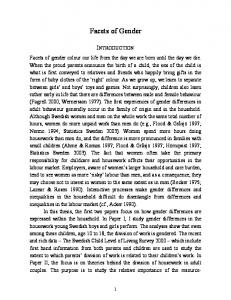
In the configuration in Figure 3.2 the robot gets help from the door it is about to cross. The door is equipped with a wide-angle camera and functionalities that can measure the position and orientation of the robot relative to the door. This information is transformed into position and orientation of door with respect to the robot before it is delivered to robot A. This configuration is an extreme case, hence all information is provided by an external source (the door) and the robot performing the task is not contributing with any information. In the two configurations in Figure 3.3 and Figure 3.4, the robot that is assigned to push the box (robot A) gets help from a second robot (robot B) with a similar set of sensors. The second robot has the advantage that it can view the scene from a distance and in that way perceive both the robot and the door at the same time.
28
CHAPTER 3. FUNCTIONAL CONFIGURATIONS
Figure 3.4: The position and orientation of a given door with respect to robot A is measured with two robots only using cameras.
In the first of these two configurations, robot A (the robot performing the “cross-door” action) only contributes with one resource, a compass. Robot B’s resources are a compass and a camera. The camera provides information to two functionalities: one that measures the position and orientation of the door, and another one that measures the position of robot A. All these measurements are computed relative to robot B. In order to compute the position and orientation of the door relative to robot A, we need to use a coordinate transformation. This in turn requires that we know, not only the relative position, but also the orientation of robot A relative to B. The later can be obtained by comparing the absolute orientations of the two robots, measured by their two on-board compasses. The configuration in figure 3.4 is similar to the one in figure 3.3, except that the orientation of robot A relative to B is obtained in another way, i.e., no compasses are used. Both robots are equipped with cameras and have a functionality that can measure the bearing to an object. When the robots look at each other, each robot can measure the bearing to the other one. By comparing these two measurements, we obtain the orientation of robot A relative to robot B.
Chapter 4
Planning for Configurations This chapter describes the problem of automatic generation of configurations, and how it can be addressed using techniques inspired by planning. This includes a problem statement, a comparison with traditional action planning, and an introduction to hierarchical planning. Section 4.4-4.6 describes our approach to the problem. First, we present the representation of the different elements of a configuration. Second, we detail the actual process of configuration planning. The chapter concludes with an illustrative example of how a configuration can be generated given the door-crossing domain. The planning algorithm and the concepts of configurations can also be found in [Lundh et al., 2005, 2006].
4.1 Problem Statement The problem to address here is how to automatically generate configurations. That is, how can we automatically connect the available functionalities with channels in a way that forms admissible configurations that sets up the information flow that is required to perform a specific task. More formally, to generate a configurations can be seen as the problem of given a set of functionalities F, a set of goals G, and a current world state s, find a configuration C consisting of a set of functionalities f ⊂ F and a set of channels Ch that connects them. For the configuration to be admissible, it must fulfill the criteria of admissibility given in Section 3.5. To generate configurations automatically, we are using an extension of a hierarchical planner. Other techniques could be used, e.g., a constraint satisfaction system [Kumar, 1992]. However, we expect that the use of a hierarchical planner will make it easier to scale up our approach to more complex scenarios, and to deal with the problem of when and how to change (replan) a configuration.
29
30
CHAPTER 4. PLANNING FOR CONFIGURATIONS
It is also shown in related areas, as program supervision and automatic web service composition, that techniques inspired by planning is suitable for this kind of problems.
4.2 Configuration Planning Versus Action Planning Action planning (or, simply, planning), usually refers to the task of creating a sequence of actions that will achieve a goal. Each action in the plan have certain conditions specifying when it is applicable, and certain conditions that are effected by the action. These conditions create causal dependencies between the actions in a plan; a causal flow determines which action should come after another. The planning process can be performed in several different ways. The two basic approaches are progression planning and regression planning. In progression planning, we a start with an initial state and search for different sequences of actions, until we find a sequence the reaches the goal. This is a quite straight-forward method, but in its purest, unguided form, it is considered impractical and inefficient. The reason for this is that progression planning consider all actions, even actions that is irrelevant. This means that at each state there can be a large amount of applicable actions that must considered, i.e., the tree to search becomes huge even for small problems. However, with heuristic techniques the search space can be significantly reduced. Regression planning works in the opposite way, the search is done from the goal to the initial state. In this way only actions relevant for achieving the current goal or subgoals are considered, resulting in a smaller search space. Configuration planning differs from action planning in that the functionalities, unlike the actions in a plan, are not temporally and causally related to each other, but related by the information flow as defined by the channels. However, a complete configuration may be seen as a (rather complex) action, with preconditions and postconditions, that can be temporally and causally related to other configurations. Thus, a plan for a group of robots corresponds to a set of temporally ordered configurations. This means that in a plan, the actions are executed in sequence. When an action is completed, the causal state will change, and the next action in the plan will become applicable and executed. Functionalities are executed in parallel, and a functionality becomes active when the input data is present. In order to achieve the data flow between functionalities, a mechanism that creates channels between functionalities is required. Such connections are not required for action planning, and obviously, no existing planning technique facilitate such a mechanism.
4.3. HIERARCHICAL PLANNING
31
4.3 Hierarchical Planning In order to combine functionalities to form admissible configurations that solve specific tasks, we have chosen to use techniques inspired by hierarchical planning, in particular the SHOP planner [Nau et al., 1999].
Figure 4.1: An example of an hierarchical structure for action planning
The idea with hierarchical planning is to take advantage of hierarchical structures. Hierarchies, in general, have a small amount of activities at each level. This is beneficial since the way to combine the activities is small, and thus of less computational cost compared to non hierarchical methods. The activities at each level in the hierarchical structures, can be decomposed to a small number of activities at the level below. This means that in the different levels of the hierarchy the actions have different granularity, i.e., lower levels are more decomposed. For example (see Figure 4.1), the action Go-to-work can be decomposed into the actions Get-bike, Bike-to-work, and Leave-bike. Each of these tasks can be further decomposed, e.g, Get-bike can be decomposed to Goto-bike and Unlock-bike. There is also a possibility to give alternative solutions to actions. In the case above, the action Go-to-work, could be decomposed into actions considering a car, a train, or similar instead of a bike.
4.4 Representation In order to generate configurations automatically, we need a declarative description of the available functionalities and their properties. This description is realized using operators similar to those of AI action planners. These operators specify the input and output information for each functionality, and may also include causal pre- and postconditions. The structure of the operators are shown below. (functionality name: functionality-name(robot, object)
32
input: output: precond: postcond:
CHAPTER 4. PLANNING FOR CONFIGURATIONS
descriptor(robot, object), ... descriptor(robot, object), ... condition(s) condition(s)
)
The name field correspond to the Id component of a functionality, and the robot parameter in the name is r in the functionality. The optional parameter object tells to which object the functionality refers to. The fields input and output correspond to I and O, and represent the data flow associated with the functionality. The input field specifies the type of data required by the functionality, which robot it is related to and which object(s) it refers to. The output field use the same format as the input field, but specifies the type of data the functionality is producing. The two optional fields precond and postcond correspond to Pr and Po, and represent the causal flow of the operator. The preconditions declare the conditions that need to be satisfied in order for the functionality to operate (e.g. a camera must be on to produce images). The postconditions refers to conditions that will be affected if the functionality is executed (e.g. a cross-door functionality infers that the robot will be in an other room after the functionality is accomplished). Note that the Φ function is not part of the operator schema; it corresponds to the actual code for executing the functionality. The format of the operators is similar for both functionalities and resources, except that for resources are either the in- or the out-field empty. Below the operators for camera, cross-door, and measure-door are shown. (functionality name: camera(r) input: output: image(r) precond: camera-on postcond: ) (functionality name: measure-door(r, d) input: image(r) output: pos(r, d), orient(r, d) precond: visible(r, d) postcond: ) (functionality name: cross-door(r, d) input: pos(r, d), orient(r, d)
4.4. REPRESENTATION
33
output: precond: open(d), in(r, rm), connects(d, rm, rm2) postcond: in(r, rm2), not(in(r, rm)) )
The output from camera is an image taken by the camera located on robot r. Since camera is a sensing resource no input is specified. In measure-door we have an image taken by camera r as input and from that we are able to compute the position and orientation of the door d relative to r as output. The action resource, cross-door, takes as input the position and orientation of the door, in coordinates relative to the robot crossing the door. The precondition for camera is that the camera is switched on, for measure-door that the door d is fully visible in the input image, and for cross-door that the door is open. Notice that the output of camera matches the input of measure-door and that the output of measure-door matches the input of cross-door. Intuitively, this means that we have an information flow camera → measure-door → cross-door and that channels between these functionalities can legally be created. This combination is equivalent to the configuration in Figure 3.1. In order to combine functionalities for specific purposes we use something called methods. Methods are the standard meta-level operators used in hierarchical planning to build hierarchies of actions. A method in the configuration framework is a way to specify the functionalities, methods, and connections that is required to produce a certain output. The structure of the methods are shown below. (config-method name: method-name(robot, object) input: f#: descriptor(robot, object), bandwidth . . . output: f#: descriptor(robot, object), bandwidth . . . precond: condition(s) postcond: condition(s) channels: channel-type(f#, f#, descriptor(robot, object), bandwidth) . . . body: f#: functionality/method-name(robot, object) . . . )
The structure is similar to the structure of the operator for a functionality. The important differences are that a method contains the fields “channels” and “body”. The body lists the functionalities and/or methods used by the method. Each functionality/method is marked with a label (f1, f2, . . . , fn). The channels field lists the channels that should be created for the method. Each channel
34
CHAPTER 4. PLANNING FOR CONFIGURATIONS
specify whether the channel is local or global, which functionalities/methods it connects, the type of data it transfers, and the bandwidth it allocates (only for global channels). The input of a method is a list of data-types with bandwidth that are labeled with the functionality/method in the body it should be connected to. The output of a method specifies the output data with bandwidth of the method and which functionality/method in the body that is producing it. It is important that connected functionality/method have an input/output of the same type. The following is an example of a method that connects camera with measure-door on the robot (r): (config-method name: get-door-info(r, d) out: f2: pos(r, d), 20 f2: orient(r, d), 10 precond: (camera(r), in(r, room), in(d, room), robot(r), door(d)) channels: (local(r), f1, f2, image(r)) body: f1: camera(r) f2: measure-door(r, d) )
There is a local channel inside the method connecting the two functionalities (labeled f1 and f2). In addition, the output of the entire method, as declared in the out field, is the position and orientation obtained from f2. Thereby, any channel that in a method higher up in the hierarchy is connected to get-door-info(r, d) will be connected to measure-door(r, d). Note that bandwidth is only specified for the output of the method and not for the channel. This since the channel in this method is local and no bandwidth needs to be allocated. The functionality operators and the methods constitute the domain of the planner. In addition to the domain, the planner needs a world state in order to generate a configuration description. A world state is a way to represent the conditions that holds in the environment for a given moment. For example, a simple world state would be: (state robot(Pippi), in(Pippi, Room1))
This states that Pippi is a robot and that Pippi is in Room1. When the planner iterates over the methods and functionalities in the domain, it must verify that the functionalities can operate in the current world state. This is done by comparing the world state with the preconditions of the method or the functionality. In the current implementation, the world state is defined by hand. Given a domain and a world state, the planner generates a configuration description. The format of the configuration description is presented below.
4.5. THE CONFIGURATION PLANNER
35
(configuration :functionalities f# functionality-name(robot, object) . . . :channels channel-type(robot, f#, f#, descriptor) . . . :cost )
The configuration description gives the information required to create a configuration. It consist of two main parts, functionalities and channels. The upper part lists the functionalities with automatically generated identifiers (f#). The lower part lists the channels. For each channel, the description gives the identifiers for the functionalities it connects and where these functionalities are located. There is also a cost associated with a configuration. This cost is declared at the bottom of the description. The next section details how the configuration planner works.
4.5 The Configuration Planner In our approach we use methods to achieve a hierarchical structure of functionalities. As explained in Section 4.4, methods define how functionalities (and methods) should be connected to generate some specific data. A method has causal preconditions specifying when it is applicable. There may be several versions of the method with different preconditions, applicable under different (or even the same) circumstances. For example (see Figure 4.4), the method get-door-info(3) is composed of the methods get-door-info(2), get-robot-orient, get-robot-pos, and the functionality transform-info. The configuration planner takes as input a current world state s, a method "stack" with initially one unexpanded method instance l : m(c1 , c2 , ...) representing the goal of the robot (l is a label), and a set of methods M and a set of functionality operators O. It also maintains an initially empty configuration C and an initially empty sets of causal postconditions P. It works as follows: 1. Take the method instance l : m(c1 , c2 , ...) at the top of the stack. 2.
(a) If the method instance is a functionality, check if it already exists in the current configuration C. If it does not, add it to the current configuration C. Go back to 1. (b) If it is a method, select an instantiated version of the method schema m from M with preconditions which are applicable in s (this is a backtrack point). If there is none, report failure and backtrack.
3. Expand the method as follows:
36
CHAPTER 4. PLANNING FOR CONFIGURATIONS (a) Instantiate the remaining fields of the selected method, and generate new unique labels instead of the general labels f1, f2 etc. (b) Add the channels of the method body (with new labels) to the current configuration C. (c) Add the method instances (with new labels) of the method body to the top of the stack. (d) Use the in and out fields of the method to reconnect any channels in C from the method instances being expanded (i.e. with label l) to the new functionality or method instance as labeled in the method body.
4. If the stack is empty, verify that C is admissible and return C and P. If C is not admissible, return failure. If the stack is not empty, go back to 1. Step 3 may need some more explanation. Assume we are expanding l5: get-door-info(robot1, door4), and we have chosen the method shown above. First, we need to replace r with robot1 and d with door4 everywhere in the schema, and room is bound to the room of robot1 (step a). New labels, say l7 and l8, replace f1 and f2 (step a). The channel is added to C (step b) and the two functionalities are added to the top of the stack (step c). Finally, according to the out field, any existing channel in C with label l5 (i.e. get-door-info) for its out connection is reconnected to l8 (i.e. measure-door) (step d). The first output from the planner is a configuration description C, which essentially consists of a set of functionality names with labels, e.g. l8: measure-door(robot1, door4), and set of channels, e.g. (l7, l8, image(robot1, door4), local(robot1)). The second output from the planner is the set of postconditions P, which can be used to update the current state, which then in turn can be used as input for generating the configuration following the current one (if any). It is possible to accidentally specify methods that can result in configurations with cycles. However, these cycles can easily be detected and the faulty configurations can be excluded. Generally, there are several configurations that can address a problem, but obviously, only one configuration per problem can be performed at the time. By trying different applicable method versions, guided by the costs of configurations, our planner generates the admissible configuration with the lowest cost first.
4.6 Example To further illustrate how our configuration planner works, we give an example of how we can automatically generate a configuration equivalent to the configuration in Figure 3.3. First, we declare the input to the configuration planner.
4.6. EXAMPLE
37
The input to the configuration planner is a set of functionality operators, a set of methods, and a current world state. The functional operators required are two types of sensing resources (camera and compass), one type of action resource (cross-door), and four types of functionalities (measure-robot-pos, measure-robot-orient-compass, measure-door, and transform-info). The main part of the functionalities above must run on the robot that is observing the door and the door-crossing robot from a distance. We use rh for parameters that are intended to represent the helping robot, and r for the doorcrossing robot. The following is an example of a method that connects camera with measure-door on the helping robot (rh): (config-method name: get-door-info(rh, d) out: f2: pos(rh, d), 20 f2: orient(rh, d), 10 precond: (camera(rh), in(rh, room), in(d, room), robot(rh), door(d)) channels: (local(rh), f1, f2, image(rh), 50) body: f1: camera(rh) f2: measure-door(rh, d) )
In a similar way, the methods get-robot-orient(rh, r), get-robot-pos(rh, r), get-door-info(rh, r, d), and the top method do-cross-door(r, d) are constructed to make the hierarchical structure shown in Figure 4.4. Note that we have two versions of (get-door-info) with different numbers of parameters. The version detailed above requires only a single robot and the other requires two robots. Below, we detail this version together with the top method, do-cross-door. (config-method name: get-door-info (rh, r, d) out: f4: pos(r, d), 20 f4: orient(r, d), 10 channels: (local(rh), f1, f4, pos(rh, d)) (local(rh), f1, f4, orient(rh, d)) (local(rh), f2, f4, orient(rh, r)) (local(rh), f3, f4, pos(rh, r)) body: f1: get-door-info(rh, d) f2: get-robot-orient(rh, r) f3: get-robot-pos(rh, r) f4: transform-info(rh, r, d) ) (config-method name: do-cross-door(r, d)
38
CHAPTER 4. PLANNING FOR CONFIGURATIONS
precond:
((robot r) (door d) (robot rh) (eval (not (eql (quote r) (quote rh))))) channels: (global(rh, r), f1, f2, pos(r, d), 20) (global(rh, r), f1, f2, orient(r, d), 10) body: f1: get-door-info(rh, r, d) f2: cross-door(r, d) )
The configuration planner needs a world state to decide if a method/functionality is applicable. In this example we use the following world state that is based on the map in Figure 4.2 and the sensors available: (state robot(Pippi), robot(Emil), door(Door1), camera(Emil), camera(Pippi), compass(Pippi), compass(Emil), in(Pippi, Room1), in(Emil, Room1), in(Door1, Room1), open(Door1), connects(Door1, Room1, Room2), medium(socket, Pippi, Emil, 200), medium(socket, Emil, Pippi, 200) )
Figure 4.2: A map of two rooms connected with a door. Robots are displayed as circles with a line giving their heading. In room1, Emil is to the left and Pippi to the right.
In this state we have two robots (Emil and Pippi) equipped with cameras and compasses, a door (Door1) that is open, and that all these objects are located in room Room1. Door1 connects Room1 with a second room (Room2). There are also a declaration of the mediums available in this state, i.e., a socket connection between Pippi and Emil with 200 in both directions. To start the planner, we use the following command: generate-configuration(do-cross-door(Pippi, Door1), domain, state)
The first parameter is the top-method (do-cross-door) instantiated with the robot (Pippi) that should cross the door (Door1). The methods and functionality operators are represented by domain. The last parameter is the current world state.
4.6. EXAMPLE
39
The first step of the planner is to take the method instance at the top of the stack. In our example this is do-cross-door(Pippi, Door1) which gives us the stack: (stack MAIN: do-cross-door(Pippi, Door1) )
The second step is to find an instantiated version of this method that is applicable in the current state. If we instantiate the do-cross-door method above, r should be replaced with Pippi and d with Door1. The preconditions of this method requires that Pippi is a robot and that Door1 is a door. There are also requirements on a second robot (rh) that is not equivalent to r (Pippi). The preconditions of do-cross-door are satisfied by the current world state and Emil can be bound to rh. This gives the bindings: r = Pippi, d = Door1, and rh = Emil. In the third step, to expand the method, the methods/functionalities of the method gets unique labels, instead of general labels (f1, f2, . . . ), and are put on the stack. The channels of the method are added to the current configuration. After the expansion of this first method, the stack and configuration have the following format: (stack F108: get-door-info(Emil, Pippi, Door1) F109: cross-door(Pippi, Door1) ) (configuration Functionalities: Channels: global(Emil, Pippi, F108, F109, pos(Pippi, Door1), 20) global(Emil, Pippi, F108, F109, orient(Pippi, Door1), 10) Cost: 26 )
At this stage, the cost of the configuration is 26 (i.e. 2 · 10 for the robots involved, plus 2·3 for the global channels). Next, the planner goes back to the first step and expands the instantiated method on the top of the stack (F108: get-door-info(Emil, Pippi, Door1)) according to the second method schema on page 37, using the bindings: rh = Emil, r = Pippi, and d = Door1. The channels of the method are added to the current configuration. With the new channels added, the cost of the configuration is now 30 (i.e. each local channel cost 1). The four methods/functionalities of F108: get-door-info are labeled F110–F113 and put on the stack. The out field of the method specifies that the output from F113: transform-info is the output from the entire method.
40
CHAPTER 4. PLANNING FOR CONFIGURATIONS
This information is used to update the existing channels in the current configuration, i.e., the global channels are now connecting F113: transform-info with F109: cross-door. The stack and configuration after the expansion of F108: get-door-info: (stack F110: F111: F112: F113: F109: )
get-door-info(Emil, Door1) get-robot-orient(Emil, Pippi) get-robot-pos(Emil, Pippi) transform-info(Emil, Pippi, Door1) cross-door(Pippi, Door1)
(configuration Functionalities: Channels: local(Emil, F110, F113, pos(Emil, Door1)) local(Emil, F110, F113, orient(Emil, Door1)) local(Emil, F111, F113, orient(Emil, Pippi)) local(Emil, F112, F113, pos(Emil, Pippi)) global(Emil, Pippi, F113, F109, pos(Pippi, Door1), 20) global(Emil, Pippi, F113, F109, orient(Pippi, Door1), 10) Cost: 30 )
The next method to expand is F110: get-door-info. After the expansion of this method according to the first method schema on page 37, the first method in the stack will be camera(Emil, Door). This method is actually a functionality and cannot be further expanded. Instead it is removed from the stack and added to the functionality list of the current configuration. This gives us the following stack and configuration: (stack F115: F111: F112: F113: F109: )
measure-door(Emil, Door1) get-robot-orient(Emil, Pippi) get-robot-pos(Emil, Pippi) transform-info(Emil, Pippi, Door1) cross-door(Pippi, Door1)
(configuration Functionalities: F114: camera(Emil) Channels: local(Emil, F114, F115, local(Emil, F115, F113, local(Emil, F115, F113, local(Emil, F111, F113,
image(Emil)) pos(Emil, Door1)) orient(Emil, Door1)) orient(Emil, Pippi))
4.6. EXAMPLE
41
local(Emil, F112, F113, pos(Emil, Pippi)) global(Emil, Pippi, F113, F109, pos(Pippi, Door1), 20) global(Emil, Pippi, F113, F109, orient(Pippi, Door1), 10) Cost: 32 )
Notice that the labels in the existing channels are updated. The cost after expanding F110: get-door-info is 32 (i.e., 30 plus 1 for the functionality and 1 for the channel). The planner continues expanding methods and adding functionalities and channels to the configuration until the stack is empty. The final configuration description given by the planner is found below: (configuration Functionalities: F109: cross-door(Pippi, Door1) F113: transform-info(Emil, Pippi, Door1) F129: measure-robot-pos(Emil, Pippi) F118: measure-robot-orient-compass(Emil, Pippi) F117: compass(Emil) F116: compass(Pippi) F115: measure-door(Emil, Door1) F114: camera(Emil) Channels: local(Emil, F114, F129, image(Emil)) global(Pippi, Emil, F116, F118, global-orient(Pippi), 10) local(Emil, F117, F118, global-orient(Emil)) local(Emil, F114, F115, image(Emil)) local(Emil, F115, F113, pos(Emil, Door1)) local(Emil, F115, F113, orient(Emil, Door1)) local(Emil, F118, F113, orient(Emil, Pippi)) local(Emil, F129, F113, pos(Emil, Pippi)) global(Emil, Pippi, F113, F109, pos(Pippi, Door1), 20) global(Emil, Pippi, F113, F109, orient(Pippi Door1), 10) Cost: 44 )
In this description, the functionality in the list are connected with each other with global or local channels. Figure 4.3 shows the graph equivalent to this description. The cost is calculated, as mentioned before, using a weighted sum of the components in the configuration. The configuration includes two robots, three global channels, seven local channels, and eight functionalities. cost(c) = 2 · 10 + 3 · 3 + 7 + 8 = 44 The cost for the configuration is 44. Before the configuration is returned, it must be verified that it is admissible. To confirm that the configuration is communication admissible the planner uses
42
CHAPTER 4. PLANNING FOR CONFIGURATIONS
CAMERA
COMPASS
COMPASS
F114 : (EMIL)
F117 : (EMIL)
F116 : (PIPPI)
IMAGE(EMIL)
IMAGE(EMIL)
GLOBAL-ORIENT(EMIL) GLOBAL-ORIENT(PIPPI)
MEASURE-ROBOT-POS
MEASURE-DOOR
MEASURE-ROBOT-ORIENT-COMPASS
F129 : (EMIL PIPPI)
F115 : (EMIL DOOR1)
F118 : (EMIL PIPPI)
POS(EMIL, PIPPI)
POS(EMIL, DOOR1) ORIENT(EMIL, DOOR1)
ORIENT(EMIL, PIPPI)
TRANSFORM-INFO F113 : (EMIL PIPPI DOOR1)
POS(PIPPI, DOOR1) ORIENT(PIPPI, DOOR1)
CROSS-DOOR F109 : (PIPPI DOOR1)
Figure 4.3: The configuration generated in the example. The colors of the boxes show where the functionalities are located, gray is Emil and white is Pippi. Global channels are represented with black bold arrows and local channels with gray thin arrows.
the medium declarations in the world state and the bandwidth of the global channels. If the configuration is communication admissible, there is a medium that each global channel can be associated with, and that the sum of allocated bandwidth for the global channels associated with that medium is with in the limits for the medium. For our example configuration we have three global channels. The first global channel is associated with medium: medium(socket, Pippi, Emil, 200)
The capacity of this medium is 200 and the global channel allocates only 10 of this. The two lower global channels are associated with medium: medium(socket, Emil, Pippi, 200)
The capacity of this medium is 200 and the global channel allocates only 30 of this. Since there is enough bandwidth on the available media, the configuration is communication admissible. In the example above we used fixed numbers to declare bandwidth. These numbers are just for illustration and are not based on actual measurements or technical specifications.
4.6. EXAMPLE
43
Information and causal admissibility are guaranteed implicitly by the planning algorithm described above, and is not verified again.
44
do-cross-door(r, d)
transform-info(rh, r, d)
measure-robot-pos(rh, r)
camera(rh)
get-door-info(rh, r, d)
get-robot-pos(rh, r)
get-robot-orient(rh, r)
measure-robot-orient-compass(rh, r)
compass(rh)
get-door-info(rh, d)
compass(r)
measure-door(rh, d)
Figure 4.4: The hierarchy of methods (gray) and functionalities (white) for cross-door.
camera(rh)
CHAPTER 4. PLANNING FOR CONFIGURATIONS
cross-door(r, d)
Chapter 5
Executing Configurations In the previous chapter we showed how we can generate a configuration description automatically. In this chapter, we will show how we can make the configuration description executable. Our approach is implemented in LISP [McCarthy, 1960, Steele, 1990] and generates code in LISP format. LISP is an abbreviation of LISt Processing and is a functional programming language often used in Artificial Intelligence. A configuration specifies which functionalities should be used, how they should be connected, what type of connection, and which robots are involved. The description in it self is not executable. However, it contains all the information required to achieve an executable configuration. In order to go from a configuration description to an executable configuration, the following issues must be considered. • First, the functionalities must be ordered such that the correct flow of information is obtained. That means that whenever one functionality provides another functionality with information, the former functionality must be executed before the later one. • Second, the configuration description generated by the planner contains the functionalities and channels for the entire configuration, but the different robots are only interested to execute the parts that belongs to themselves. This means that there is a need for a mechanism that categorize and then divide the different functionalities and channels according to the robot they belong to. For functionalities and local channels, this is not a big problem. Global channels on the other hand must be treated specially since they concern more than one robot. • Third, the overall configuration is generated at one single robot. In addition to the division of the configuration, there is also a need for a mechanism that deploys the different parts of the configuration to the concerned, individual robots.
45
46
CHAPTER 5. EXECUTING CONFIGURATIONS • Finally, at the individual robots, how do we practically implement or activate the functionalities? How do we implement the channels that transports the information? How can we achieve transparency toward functionalities for local and global channels? How should the data on the channels be transferred? Should the data be overwritten by newer data or should there be some sort of queue inside the channels?
In this chapter we will address these issues and show the steps required to transform a configuration description into executable code. We will also continue on the example given in chapter 4 and show how this particular configuration can be made executable. In the final section of the chapter, we will discuss the problem of deciding when a configuration becomes inadmissible during execution, and how this can be addressed with monitoring of the execution.
5.1 Sort, Divide, and Deploy Configurations The first step to make a configuration executable is to order the functionalities such that the desirable information flow can be obtained. That is, functionalities with no input must precede the functionalities they provide with input, and these functionalities in their turn must precede the functionalities they provide with input and so on. The following algorithm describes how this is obtained. Input to the algorithm is a unsorted configuration description uC. Output is an initially empty sorted configuration description sC. The algorithm also keeps track of a FIFO-list1 c for channel identifiers. 1. Find a functionality f ∈ uC whose all input channels are in c. (For a channel with no input, this trivially holds.) Add output channels of f to c. Add f to end of sC. 2. If no such f can be found and if uC 6= ∅, return that the configuration contains cycles and can not be sorted. 3. If uC 6= ∅ goto 1, otherwise return sC. The algorithm for planning configurations (see Section 4.5) can output configurations with cycles, if methods are defined inappropriatly. Cycles are instead detected at step 2 in the sorting algorithm. If there are no functionalities in whose all input channels are in c and the unsorted configuration contains functionalities, the configuration contains cycles. When we divide a configuration, we categorize the different components of a configuration with respect to where they should be executed. This is a rather straight forward process for functionalities and local channels since there is a field in the description that specifies location. Global channels are treated in 1 The
first element that is put in the list is the first element that will come out
5.2. IMPLEMENTATION OF BASIC COMPONENTS
47
a different way. Each global channel refers to two robots, and therefore both robots gets one end of the channel. In order to distribute the configuration descriptions to the correct robots we label the individual configurations with the name of the robot they belong to. The individual configurations are transferred to the robots through a predefined socket connection.
5.2 Implementation of Basic Components Before we describe how configurations are translated, we need to describe how the basic componentes of a configuration, the functionalities and channels, can be implemented.
5.2.1
Functionality
Each functionality in the configuration description has a matching functionality implemented on a robot. This implementation consist of two parts: a wrapper function, and the actual function. The wrapper provides a standard interface to the configuration with a specification of the input and output data. If all the input information is provided and all the preconditions are fulfilled, the actual function is executed and produces information according to the specification. If there is missing input, the wrapper function exits without activating the actual functionality. The configuration executes a functionality through a function call to the wrapper function. The function call for measure-door (in LISP notation) is given below. (measure-door ’Door1 CH-4 (LIST CH-5) (LIST CH-6))
The parameters to the function specify the object we are interested in (’DOOR1), the input channel (CH-4), and the output channels ((LIST CH-5) (LIST CH-6))). Each input has its own channel. A functionality can provide several other functionalities with data. Therefore, for each type of output data, a list of channels is specified.
5.2.2
Channel
A channel is a data structure that keeps track of: • whether it is local or global, • the destination robot, in case it is global, • the type of data, • the input and output functionalities,
48
CHAPTER 5. EXECUTING CONFIGURATIONS • the actual data transmitted, and • whether the last operation was reading from or writing to the channel.
A channel can only store one item of data at the time. The data in a channel is not stored in a buffer. If a functionality writes to a channel, the old data is replaced with the new data. There is only one type of data for each channel. That means that if a functionality produces two different outputs, two different channels are required. If the functionality produces the same data for several functionalities, each receiving functionality needs a channel. The channels of a configuration are not implemented prior to configuration generation, i.e., channels must be created during the transformation from description to executable code. The interface to the associated functionalities is common for local and global channels. Although the implementation of local and global channels are different, the interface allows functionalities to write to and read from channels in a transparent way. Local Channels A local channel is created by instantiating the data structure above using information from the configuration description. The following function call creates a local channel associated with functionality F114 and F129. The data type is an image taken by Emil. (make-local-channel ’Emil ’F114 ’F129 ’(image Emil))
In this example, when functionality F114 produces output, it will write its data in the "actual" data field. Such a write operation changes the last operation field to "write". Further, when the wrapper function of functionality F129 is activated, it will sense that new data is on the channel since the last operation was "write". While doing this, the last operation will be set to "read" and the data will be used as input to the actual function. Global Channels A global channel is created by instantiating the data structure from the configuration description on the two robots at each end of the channel. 1. (make-global-channel ’EMIL ’F116 ’F118 ’(GLOBAL-ORIENT PIPPI)) 2. (make-global-channel ’PIPPI ’F116 ’F118 ’(GLOBAL-ORIENT PIPPI))
The above example shows how the global channel between F116 on Pippi and F118 on Emil is created. (1.) is created on Pippi and (2.) on Emil. As mentioned before, to write to and to read from a global channel and local channel is identical. In the example above, when functionality F116 writes to the global channel, it will write to the actual data field in the instance at Pippi. The write operation copies the data to the instance at Emil through a socket connection. Thus, the instance on Emil will make the data accessible to functionality F118.
5.3. TRANSLATION OF CONFIGURATION DESCRIPTION
49
5.3 Translation of configuration description The fourth step is to transform the individual configuration description into code executable by the robot. The individual description consist of two parts: one part that describes the channels, and one part that describes the functionalities. The task here is to transform the description into an executable configuration that creates the channels and executes the functionalities. The executable individual configurations have the following format: (LET ((CH-1 (function that create local/global channel ) . . . (CH-n (...))) (LAMBDA () (PROGN (function call to functionality ) . . . (...))) )
The upper part (the LET statement) defines the channels and binds them to variables local to the configuration. The lower part (the LAMBDA expression) encodes the functionalities to execute. The functionalities use the channels defined in the LET statement to transport their data. As explained in Section 5.2.1, functionalities can have several different inputs, each input with a separate channel. A functionality can also have several different types of output. Each output have a list of channels that the data should be put on. The following algorithm describe how we, given an individual configuration description, can get an executable configuration. 1. Create a LET statement. 2. Go through the list of channels. Label them CH-1, CH-2, . . . , CH-n according to their position in the list. Add the channels to the LET statement: Check if the channel is local or global. If it is local define a makelocal-channel. If it is global, check the robot fields and define a makeglobal-channel with the other robot as first parameter. 3. Create a LAMBDA expression enclosed in the LET statement. 4. Go through the list of functionalities according to these steps: (a) Take the first functionality in the list. (b) Search through the list of channels for inputs. For each channel, check if the output of the channel (third parameter) is identical to the label (F#) of the current functionality. If so, add the channel label
50
CHAPTER 5. EXECUTING CONFIGURATIONS (CH-#) to the input of the functionality at the position specified by the data type. (c) Search through the list of channels for outputs. For each channel, check if the input of the channel (second parameter) is identical with the label (F#) of the current functionality. Add the channel label (CH-#) to the list of outputs of the functionality at the position specified by the data type.
5. Add the functionality to the LAMBDA expression. If the list of functionalities is empty, close the LAMBDA expression and the function, otherwise, goto 4.
5.4 Example The example in this section continues on the example from chapter 4. Here we will show how the overall configuration description generated by the planner can be divided and transformed into individual executable configurations. Recall the following configuration description: (configuration Functionalities: F109: cross-door(Pippi, Door1) F113: transform-info(Emil, Pippi, Door1) F129: measure-robot-pos(Emil, Pippi) F118: measure-robot-orient-compass(Emil, Pippi) F117: compass(Emil) F116: compass(Pippi) F115: measure-door(Emil, Door1) F114: camera(Emil) Channels: local(Emil, F114, F129, image(Emil)) global(Pippi, Emil, F116, F118, global-orient(Pippi) 10) local(Emil, F117, F118, global-orient(Emil)) local(Emil, F114, F115, image(Emil)) local(Emil, F115, F113, pos(Emil, Door1)) local(Emil, F115, F113, orient(Emil, Door1)) local(Emil, F118, F113, orient(Emil, Pippi)) local(Emil, F129, F113, pos(Emil, Pippi)) global(Emil, Pippi, F113, F109, pos(Pippi, Door1) 20) global(Emil, Pippi, F113, F109, orient(Pippi Door1) 10) Cost: 44 )
The first step is to order the functionalities according to the data flow. If we look at the configuration above, there are three functionalities without input: F117: compass(Emil) F116: compass(Pippi)
5.4. EXAMPLE
51
F114: camera(Emil, Door1)
These functionalities must be first in the list. The outputs of these functionalities are transported by the following channels: local(Emil, F114, F129, image(Emil)) global(Pippi, Emil, F116, F118, global-orient(Pippi)) local(Emil, F117, F118, global-orient(Emil)) local(Emil, F114, F115, image(Emil))
The channels specify which functionalities should come next in the functionality list (F129, F118, and F115). By continue in this way, the order of functionalities is determined, and becomes: F117: F116: F114: F129: F118: F115: F113: F109:
compass(Emil) compass(Pippi) camera(Emil) measure-robot-pos(Emil, Pippi) measure-robot-orient-compass(Emil, Pippi) measure-door(Emil, Door1) transform-info(Emil, Pippi, Door1) cross-door(Pippi, Door1)
In the second step, we divide this configuration into two configurations, one with the components that belongs to Pippi and one with the components that belongs to Emil. If we look at the description above, we can see that the first parameter of functionalities and local channels give the location of the component. For global channels, the two first parameters give this information. The individual descriptions look as follows. (configuration Pippi Functionalities: F109: cross-door(Pippi, Door1) F116: compass(Pippi) Channels: global(Pippi, Emil, F116, F118, global-orient(Pippi) 10) global(Emil, Pippi, F113, F109, pos(Pippi, Door1) 20) global(Emil, Pippi, F113, F109, orient(Pippi Door1) 10) ) (configuration Emil Functionalities: F113: transform-info(Emil, Pippi, Door1) F129: measure-robot-pos(Emil, Pippi) F118: measure-robot-orient-compass(Emil, Pippi) F117: compass(Emil) F115: measure-door(Emil, Door1) F114: camera(Emil) Channels:
52
CHAPTER 5. EXECUTING CONFIGURATIONS
local(Emil, F114, F129, image(Emil)) global(Pippi, Emil, F116, F118, global-orient(Pippi) 10) local(Emil, F117, F118, global-orient(Emil)) local(Emil, F114, F115, image(Emil)) local(Emil, F115, F113, pos(Emil, Door1)) local(Emil, F115, F113, orient(Emil, Door1)) local(Emil, F118, F113, orient(Emil, Pippi)) local(Emil, F129, F113, pos(Emil, Pippi)) global(Emil, Pippi, F113, F109, pos(Pippi, Door1) 20) global(Emil, Pippi, F113, F109, orient(Pippi Door1) 10) )
Note that the global channels appear in both configurations. In order to transform these we apply the algorithm given in Section 5.3. The next step is to go through the list of channels and add definitions of local and global channels in a LET statement. For Pippi, we create three global channels and for Emil we create three global channels and seven local channels. Further we go through the list of functionalities and add them to the LAMBDA expression, with the channel variables as in- and outputs. The finished executable configurations are shown below. PIPPI: (LET ((CH-1 (make-global-channel ’Emil ’F116 ’F118 ’(global-orient Pippi))) (CH-2 (make-global-channel ’Emil ’F113 ’F109 ’(pos Pippi Door1))) (CH-3 (make-global-channel ’Emil ’F113 ’F109 ’(orient Pippi Door1)))) (LAMBDA NIL (PROGN (compass (LIST CH-1)) (cross-door ’Door1 CH-2 CH-3))) ) EMIL: (LET ((CH-1 (make-local-channel ’Emil ’F128 ’F129 ’(image Emil))) (CH-2 (make-global-channel ’Pippi ’F116 ’F118 ’(global-orient Pippi))) (CH-3 (make-local-channel ’Emil ’F117 ’F118 ’(global-orient Emil))) (CH-4 (make-local-channel ’Emil ’F114 ’F115 ’(image Emil))) (CH-5 (make-local-channel ’Emil ’F115 ’F113 ’(pos Emil Door1))) (CH-6 (make-local-channel ’Emil
5.5. MONITORING THE EXECUTION
53
’F115 ’F113 ’(orient Emil Door1))) (CH-7 (make-local-channel ’Emil ’F118 ’F113 ’(orient Emil Pippi))) (CH-8 (make-local-channel ’Emil ’F129 ’F113 ’(pos Emil Pippi))) (CH-9 (make-global-channel ’Pippi ’F113 ’F109 ’(pos Pippi Door1))) (CH-10 (make-global-channel ’Pippi ’F113 ’F109 ’(orient Pippi Door1)))) (LAMBDA NIL (PROGN (compass (LIST CH-3)) (camera (LIST CH-1 CH-4)) (measure-robot-pos ’Pippi CH-1 (LIST CH-8)) (measure-robot-orient-compass ’Pippi CH-3 CH-2 (LIST CH-7)) (measure-door ’Door1 CH-4 (LIST CH-5) (LIST CH-6)) (transform-info ’Pippi ’Door1 CH-7 CH-8 CH-6 CH-5 (LIST CH-10) (LIST CH-9)))) )
When Pippi and Emil run their configurations, they will both start to run the compass functionality. Pippi will put its global-orient on channel CH-1 on Pippi, and Emil will put its global-orient on channel CH-3 on Emil. Then the cross-door functionality on Pippi will wait for input on channel CH-2 and CH-3. Emil will run the camera that puts images on channel CH-1 and CH-4. measure-robot-pos will see if there is any input on channel CH-1. If there is input, the functionality will produce the position of Pippi with respect to Emil and put it on channel CH-8. measure-robot-orient-compass needs global orientation from both Emil (CH-3) and Pippi (CH-4). If both inputs are present, the orientation of Pippi with respect to Emil will be put on channel CH-7. Before transform-info can run, the measure-door functionality takes the image on channel CH-4 and puts the position of Door1 on channel CH-5 and the orientation on channel CH-6. Now all the inputs of transform-info are present and it can produce the position and orientation of Door1 with respect to Pippi, and send this data through channel CH-10 and CH-9. Pippi can now use the data in the cross-door behavior.
5.5 Monitoring the Execution While executing a configuration, there are a number of circumstances that may make an admissible configuration inadmissible. Two examples of such circumstances are when a sensor resource may come inaccessible due to a robot breakdown or communication errors, and when the environment changes. More concretely when an obstacle appear in the environment. In order to deal with such circumstances, a way to detect when a configuration becomes inadmissible is adequate. This can be done by constantly mon-
54
CHAPTER 5. EXECUTING CONFIGURATIONS
itoring the execution of the configuration. A simple kind of monitoring would be to check if the preconditions of the configuration holds for every cycle. This would of course not be adequate for most problems, but it would be able to detect some problems that is due to changes in the surrounding environment. When an inadmissibility is detected by the monitoring process, the system can reconfigure either by planning for a new configuration or by repairing the old configuration. Work on monitoring configuration execution is not implemented in the work presented in this thesis.
Chapter 6
Experiments We have implemented the approach described above, and conducted a series of experiments using real robots equipped with different sensors. The goal of these experiments is to demonstrate that by using the configuration framework, robots are able to setup the functionalities and channels required to perform tasks that requires tight coordination. Further, the experiments are intended to test the different parts of the framework, that is: 1. selection of the configuration to execute, 2. division of the configuration into individual configurations, 3. deployment of the individual configurations to the robots, 4. translation of the configuration into executable code, and 5. execution of the configurations Three different experiments have been conducted: two that that involve online planning and excecution on real robots, and a third experiment only testing the configuration planner. For the given goal of the experiments, to perform the experiments in a qualitative manner is more adequate than a to perform them in a quantative manner. Hence, a quantative performance would mainly test the actual implementation of the functionalities, not the different parts of our configuration framework. To test the framework, it is enough that the robots are able to perform the task once. Note that these experiments were conducted before communication admissibility was introduced in the planner. Therefore, media are not described in the world states and bandwidth consumption is not declared for global channels and method outputs. In this chapter we will first introduce the robotic platform and then go trough each experiment in separate sections.
55
56
CHAPTER 6. EXPERIMENTS
Figure 6.1: The robots used in the experiments. From left to right: Emil, Pippi and Rasmus.
6.1 The Robot Platform In the experiments conducted on real robots we have used two Magellan Pro Robots from iRobot Corporation. The two robots, called Emil and Pippi, are shown in Figure 6.1. The Magellan Pro robots are rather small with a height of 25 cm and diameter of 40 cm. The robots have three wheels; two wheels on each side with differential drive and a third rear wheel (for balance) that rotates freely. The two driving wheels are equipped with encoders for odometry measurements. Moreover, this platform has three different types of distance/occupancy sensors mounted together, equally distributed around the robot, enabling the robot to sense obstacles in all directions. These sensors are 16 tactile sensors (bumpers), 16 infrared senors, and 16 sonars. Both robots are equipped with a flux gate compass. The sensors mentioned above are the same for both robots. In addition to theses sensors, Emil is equipped with a SICK laser range finder and a simple fixed color camera. The additional sensors on Pippi are an electronic nose and a color camera mounted on a pan-tilt unit. In the conducted experiments, only a subset of the mentioned sensors are used. Each robot runs an instance of the layered hybrid architecture Thinking Cap [Saffiotti et al., 1995] and the PTL-planner [Karlsson, 2001]. Both robots are also running an instance of the configuration framework presented in this thesis. To interpret the information from the cameras, there is a vision system
6.2. CROSS A DOOR
57
Figure 6.2: A map of two rooms connected with a door. Robots are displayed as circles with a line giving their heading. In room1, Emil is to the left and Pippi to the right.
that can identify simple predefined shapes using color segmentation. In order to use this simple vision system, the shapes that need to be identified must be dressed in uniform colors. The third experiment was not run onboard real robots. However, the two Magellan Pro robots described above are used as models for available resources and functionalities. A third robot, an ATRV Jr. from iRobot Corporation, is also used as a model. This is an outdoor robot called Rasmus, shown to the right in Figure 6.1. Rasmus is equipped with a laser range finder, sonars, several cameras, wheel encoders, compass, etc.
6.2 Cross a Door The aim of this experiment is to demonstrate that by enabling robots to cooperate through functional configurations, robots can help each other to solve individual tasks in alternative ways. That is, a robot with broken sensors or a poor sensor suite can “ask” other robots for help. The robot can then generate a configuration that enables the robot to share functionalities such that the robot is able to perform its task. Hence, the success criteria for this experiment is that the robot is able to perform the assigned task by using the configuration framework.
6.2.1
Setup
To test this, we have setup an experiment similar to the example given in chapter 3. In the setup we have two robots, Emil and Pippi, and two rooms, R1 and R2. Both rooms are square-shaped with sides of 3 meters. Figure 6.2 shows the map of the environment with Emil and Pippi at their initial positions. The rooms are connected with a door that the robots must pass through.
58
CHAPTER 6. EXPERIMENTS
Figure 6.3: Emil is guiding Pippi through the door. Door posts and robots are “dressed” in uniform colors.
In order to cross the door, the robots must be aware about the position and orientation of the door relative to themselves. Under normal circumstances, when the robots can use sonars and odometry, this is not a difficult task. However, there are circumstances that makes it harder to perform the task, for example, when pushing a box these sensors will produce unreliable data. Hence, the odometry will drift and the position and orientation will not be accurate. It can also be the case that one of the robots, or even both, lacks this type of sensors. To show that it is possible to solve this task cooperatively, without sonars and odometers, the robots are restricted to only use the cameras and compasses. The cameras are fixed and can only measure distances to objects further away than 2 meters. Some modifications to the environment have been carried out in order to simplify the vision task, e.g., the door and the robots have been marked with uniform colors (see Figure 6.3). If the robots can performs this task by executing the configurations produced by the configuration planner, we can say that the experiment has been successful.
6.2.2
Execution
The configurations were generated and used as follows: 1. Pippi and Emil are in Room1. Pippi wants to go from Room1 to Room2. Since the camera can only measure distances to objects further away than 2 meters, Pippi is not be able to perform the action on its own. Emil is equipped with the same sensors as Pippi, but since Emil is not crossing the door it is able to observe both the door and Pippi from a distance during the whole procedure. This gives the following current world state:
6.2. CROSS A DOOR
59
(state robot(Pippi), robot(Emil), door(Door1), camera(Emil), camera(Pippi), compass(Pippi), compass(Emil), in(Pippi, Room1), in(Emil, Room1), in(Door1, Room1), open(Door1), connects(Door1, Room1, Room2) )
This state is entered by the operator, and the functionality operators and methods in Appendix A.1 that constitutes the domain is also made available for the configuration planner. Then, the operator starts the planner with the following command: generate-configuration( do-cross-door(Pippi, Door1), domain, state)
With the goal do-cross-door, the configuration planner generates two different configurations with costs of 44 and 47. Because of the lower cost, the upper configuration in Figure 6.4 is selected. This configuration is then deployed and executed by Pippi and Emil. (The configuration with the higher cost is similar to the bottom configuration in Figure 6.4, but with roles exchanged). During the execution of “cross-door”, Pippi continuously receives information about the position and orientation of the door. When Pippi enters Room1 she signals that the task is accomplished. This signal is received by Emil and the current configuration is played out. 2. Next, it is Emil’s turn to get the task of going from Room1 to Room2. The domain is still the same as for Pippi, but the state is updated by the operator since Pippi is now in Room2 and not in Room1. As before, the domain and state are made available for the configuration planner. The operator gives the command: generate-configuration( do-cross-door(Emil, Door1), domain, state)
The same configurations as before is generated and used to solve this task, but with the roles exchanged — i.e., Pippi is now guiding Emil. 3. However, this time during the execution of the “cross-door” behavior, the compass on Emil starts to produce incorrect data due to a disturbance in the magnetic field. This makes the current configuration not admissible, and a reconfiguration is necessary to proceed. Note that our current version of the configuration framework is not able to detect that a reconfiguration is needed, and in this experiment this detection is done manually. That is, the human operator simulates this situation by aborting the running configuration, updating the world state and starting the
60
CHAPTER 6. EXPERIMENTS
CAMERA
COMPASS
COMPASS
F28 : (EMIL)
F17 : (EMIL)
F16 : (PIPPI)
IMAGE(EMIL, PIPPI)
IMAGE(EMIL, DOOR1)
GLOBAL-ORIENT(EMIL) GLOBAL-ORIENT(PIPPI)
MEASURE-ROBOT-POS
MEASURE-DOOR
MEASURE-ROBOT-ORIENT-COMPASS
F29 : (EMIL PIPPI)
F11 : (EMIL DOOR1)
F18 : (EMIL PIPPI)
POS(EMIL, PIPPI) POS(EMIL, DOOR1) ORIENT(EMIL, DOOR1)
ORIENT(EMIL, PIPPI)
TRANSFORM-INFO F9 : (EMIL PIPPI DOOR1)
POS(PIPPI, DOOR1) ORIENT(PIPPI, DOOR1)
CROSS-DOOR F5 : (PIPPI DOOR1)
CAMERA
CAMERA
F24 : (EMIL)
F22 : (PIPPI)
IMAGE(EMIL, PIPPI)
IMAGE(PIPPI, EMIL)
MEASURE-ROBOT-ANGLE
MEASURE-ROBOT-ANGLE
F25 : (EMIL PIPPI)
F23 : (PIPPI EMIL)
IMAGE(PIPPI, EMIL)
IMAGE(PIPPI, DOOR1)
MEASURE-ROBOT-POS ANGLE(EMIL, PIPPI)
ANGLE(PIPPI, EMIL)
F27 : (PIPPI EMIL)
MEASURE-ROBOT-ORIENT-CAMERA
MEASURE-DOOR
F21 : (PIPPI EMIL)
F11 : (PIPPI DOOR1)
POS(PIPPI, EMIL)
ORIENT(PIPPI, EMIL)
ORIENT(PIPPI, DOOR1) POS(PIPPI, DOOR1)
TRANSFORM-INFO F9 : (PIPPI EMIL DOOR1)
POS(EMIL, DOOR1) ORIENT(EMIL, DOOR1)
CROSS-DOOR F5 : (EMIL DOOR1)
Figure 6.4: A configuration for the cross a door experiment. Top: Pippi crosses the door with help from Emil. Orientation from on board compasses. Bottom: Emil crosses door with help from Pippi. Orientation from cameras.
6.3. CARRY A BAR
61
configuration planner again. Since the robots are not able to use the compasses to get the orientation of each other, the compasses are removed from the current world state. This gives the following current state: (state robot(Pippi), robot(Emil), door(Door1), camera(Emil), camera(Pippi), in(Pippi, Room2), in(Emil, Room1), in(Door1, Room1), open(Door1), connects(Door1, Room1, Room2) )
With this state, only the bottom configuration in Figure 6.4 is generated and selected. This configuration does not use the compasses to obtain the orientation differences, and is therefore still admissible. Instead, this measurements is obtained by having the two robots constantly facing each other. In this way, the robots are able to measure the bearing to each other, and with this information it is possible to calculate the orientation differences. This new configuration is used to carry out the remaining part of the task.
6.2.3
Summary
The schema in Figure 6.5 summarizes the experiment. Pippi generated a configuration that made Emil help her to cross the door. After the execution of this configuration, Pippi successfully reached room R2. Emil then got the task to also go to room R2. He generated a configuration in which Pippi helped Emil to cross the door. That configuration became inadmissible and Emil reconfigured such that he could continue to perform the task. After the execution of that configuration, Emil also successfully reached room R2. Figure 6.6 shows the trajectories performed by the robots in a sample run of this experiment. In the picture, Pippi is standing still at the observing position and Emil has just accomplished its task.
6.3 Carry a Bar The second experiment is an object transportation experiment. Object transportation is usually considered to require tight coordination. The aim of this experiment is to demonstrate that the configuration framework can address a traditional tight coordination task that involves the motion of two robots. For this experiment to be successful, the robots must generate a configuration that is used to carry out the object transportation task.
62
CHAPTER 6. EXPERIMENTS
Figure 6.5: A schema of the cross a door experiment. Arrows with dot end denotes manual interventions. Double arrow denotes continuous information flow.
6.3. CARRY A BAR
63
Figure 6.6: Pippi and Emil have both reached room R2. Gray dots show Pippi’s trajectory and black dots show Emil’s trajectory.
Figure 6.7: The experimental setup for the carry bar experiment. Right: the stand that enables the robot to hold the bar.
6.3.1
Setup
As in the previous experiment, the two robots Pippi and Emil are used. To enable the robots to carry objects, we have mounted a stand on each robot that is able to hold a bar. The stand is constructed in a way so the bar is resting in it and is not physically gripped. This gives the robot a bit more freedom in terms of the accuracy of their motions; they are allowed to not be perfectly synchronized in their motions. The bar is placed in the stands of the two robots by a human operator A and the task is to transport it to a human operator B in the other room. The sensors available in this experiments are laser, sonars and odometry on Emil. For Pippi, sonars and odometry are available. Figure 6.7 shows a picture of the two robots with the bar. The picture to the right shows a close up of the stand. In the cross door experiment it was relatively clear that in order for a robot to cross a door it needs to know the position and orientation of the door to
64
CHAPTER 6. EXPERIMENTS
cross. In contrast, it is not clear what kind of information the robots require in order to cooperatively carry the bar. Hence, there are various ways to carry a bar. For example, the robots can carry the bar with one robot going first and the other robots simply following the first. One alternative way to carry the bar would be to go side by side. These two solutions would require different information. Further, there are several ways to keep the distance when carrying a bar in a lead-follow manner. If possible, the robot can measure the force/moment from the object. The following robot can than adjust its speed according to the push or pull force (e.g. as in [Wang et al., 2004]). If the robot is not able to directly sense these forces, information about angle to, distance to, and speed of the leading robot can work in a similar way. In theory, the information about the distance and angle would be enough to perform the carry task, letting the following robot keeping the distance. In order to get an accurate and smooth behavior this assumes that the information is received continuously. In practice, it is better to also use the speed (the derivative of position) to get a more accurate and smooth behavior. There is also another aspect to consider. If we adopt a simple lead-follow behavior, the following robot is responsible of keeping up with the lead robot. This is not always a good solution. The following robot can run into problems and in that case the leading robot must slow down or stop to assure that the object is not dropped. Therefore, it is necessary that the leading robot is aware of at least the distance to, but preferably also the speed of, the following robot. There are probably many more data that can be measured or extracted to make the robots transport an object in a better manner. However, the aim of this experiment is not to make the robots carrying the bar in all possible ways and it is not to make them perform the task perfectly. As stated previously, the aim is to demonstrate that it is possible to address this type of task with our configurations, i.e., to automatically generate configurations, divide, translate, deploy, and finally execute the configuration. Therefore, in this experiment we are satisfied with that the “following” robot uses the distance and angle to the leading robot and also the relative speed between the robots. For the leading robot we need to know the distance between the robots.
6.3.2
Execution
The scenario of the experiment is as follows: The task is for Pippi to transport a bar from A to B with help from Emil. With the conditions described above, the current world state is as follows: (state robot(Pippi), robot(Emil), sonars(Pippi), sonars(Emil), odometer(Pippi), odometer(Emil), laser(Emil), in(Pippi, Room1), in(Emil, Room1) )
6.3. CARRY A BAR
65
The functionality operators and methods in Appendix A.2 constitutes the domain for the task. When the operator gives the state, domain and the goal (do-carry-bar Pippi), the configuration planner generates three configurations, two of which are shown in Figure 6.8. The third configuration is similar to the second, but with roles changed, i.e., Pippi follows Emil. The cost of the configuration at the top of the figure is 33 and the cost of configuration at the bottom is 45. Since the top configuration has a lower cost, this is selected, divided and deployed to the robots. While executing this configuration, Emil is measuring the angle and distance to Pippi. The distance is transfered to Pippi trough a global channel but also to a functionality that calculates the speed. This functionality has a memory and access to a clock. The lead-robot action uses the information of distance to not make the distance too long and the follow-robot uses the distance, angle, and speed to smoothly keeping up with Pippi. During the execution of this configuration, the laser fails for some reason. This makes the configuration inadmissible and a reconfiguration is required. This situation is simulated by the operator by stopping the execution of the current configuration, updating the world state and then running the configuration planner with the new state. When the laser is unavailable, the current world state looks as follows: (state robot(Pippi), robot(Emil), sonars(Pippi), sonars(Emil), odometer(Pippi), odometer(Emil), in(Pippi, Room1), in(Emil, Room1) )
For this state, the configuration generates only the two expensive configurations, with costs of 45. The configuration at the bottom in Figure 6.8 is selected. When configurations have equal cost, the order of the method specifications in the domain decides the order of the configurations. That is, there are two versions of the top method for this experiment: one in which the helper follows and one in which the helper leads. In the configuration in the figure, Pippi is the leader and Emil is the follower, and in the configuration not shown, the roles are vice versa. While executing the configuration in Figure 6.8, Emil and Pippi must localize in the environment with their sonars and the odometry. The position information is sent to a functionality that calculates the distance and angle to Pippi in Emil coordinates. The other parts of the configuration is the same as for the configuration with the laser. With this configuration, Pippi and Emil is able to successfully carry the bar from human operator A to human operator B. See Figure 6.9.
66
CHAPTER 6. EXPERIMENTS
LASER F4 : (EMIL)
LASER-READING(EMIL)
MEAS-ROBOT-ANGLE-DIST-LASER F5 : (EMIL PIPPI)
DIST(EMIL, PIPPI)
DIST(EMIL, PIPPI)
LEAD-ROBOT
CALC-ROBOT-SPEED-DIFF ANGLE(EMIL, PIPPI)
DIST(EMIL, PIPPI)
F3 : (PIPPI EMIL)
F1 : (EMIL PIPPI)
SPEED-DIFF(EMIL, PIPPI)
STALK-ROBOT F2 : (EMIL PIPPI)
SONAR
ODOMETER
SONAR
ODOMETER
F22 : (PIPPI)
F21 : (PIPPI)
F10 : (EMIL)
F9 : (EMIL)
SONAR-READING(PIPPI) ODOMETRY(PIPPI)
SONAR-READING(EMIL) ODOMETRY(EMIL)
LOCALIZE-SONAR
LOCALIZE-SONAR
F23 : (PIPPI)
F11 : (EMIL)
GLOBAL-POS(PIPPI)
GLOBAL-POS(EMIL)
MEAS-ROBOT-ANGLE-DIST-LOCALIZER F8 : (EMIL PIPPI)
DIST(EMIL, PIPPI)
DIST(EMIL, PIPPI)
LEAD-ROBOT
CALC-ROBOT-SPEED-DIFF ANGLE(EMIL, PIPPI)
DIST(EMIL, PIPPI)
F3 : (PIPPI EMIL)
F1 : (EMIL PIPPI)
SPEED-DIFF(EMIL, PIPPI)
STALK-ROBOT F2 : (EMIL PIPPI)
Figure 6.8: Two configurations generated for two robots that carry a bar. Top: Emil uses laser to measure angle and distance to Pippi. Bottom: Both robots are localized and global positions are used to calculate necessary information
6.4. BUILD A WALL
67
Figure 6.9: Pippi and Emil have reached human operator B. Diamonds(⋄) show Pippi’s trajectory and pluses(+) show Emil’s trajectory.
6.3.3
Discussion
In this experiment, two robots are able to carry a bar using the configuration framework. We choose to only use one set of information required by the action resources. Further, we choose to use only two ways to measure/extract the information of angle and distance. These two ways could probably be combined to get more accurate data. There also exist alternative action resources and alternative methods to measure this information. For example, sonars could be used instead of laser to measure angle and distance and laser could be used instead of sonars to localize. The aim of this experiment was not to give all possible configurations but to show that it is possible to address tight coordination tasks such as object transportation. The experiment meets this aim successfully. The experiment also demonstrates the importance of developing a good selection method. It is not necessarily the cost that should controll the selection of configuration. In the case of this experiment, the configuration using laser is less reliable than the configuration using localization.
6.4 Build a Wall The third experiment has not been implemented on real robots. The goal of this experiment is to show that our configuration planner is able to construct plans for slightly more complex scenarios, with more than two robots. If the configuration planner can generate admissible configurations for this experiment, we can say that it was successful.
68
CHAPTER 6. EXPERIMENTS
To test the configuration planner, we start from the scene in Figure 6.10. In the figure we see two robots (Pippi and Emil) that push a block. The third robot (Rasmus) is observing the scene. As the figure shows, Emil and Rasmus are equipped with laser scanners.
Figure 6.10: Two robots that push a block in order to align it with the rest of the wall. Here, they get guidance from a third robot.
The task here is to build a wall using wall blocks. In this process, the blocks must be perfectly aligned when put together. The blocks are too large and heavy to be pushed by one single robot. It is possible for two robots to push the blocks. In order to align the block with the wall, the robots must be able to measure the position and orientation of the block with respect the wall. It is hard, if not impossible, for two robots using only sonars to get a good alignment of the block. If the robot closest to the wall (Emil in Figure 6.10) is equipped with a laser scanner, the measurements of the block and wall are more accurate, and a better alignment can be achieved. However, even with a scanner, a good alignment is complicated to achieve. While the robot is pushing the block, the block may occlude the wall so that the laser can not register the wall. To avoid such problems, a third robot (Rasmus in Figure 6.10) standing on the other side of the block, can guide the two robots pushing the block. In this example, we have several sensors on the robots that can be used to register the same features in the environment. For example, Emil can use both sonars and laser to measure the orientation of the block in local coordinates. Even though the laser outperforms the sonars with respect to accuracy, it is good to have alternatives in case of sensor failure. It is also possible to combine
6.4. BUILD A WALL
69
the information from the different sensors and in that way get more reliable data. The following world state is used: (state robot(Pippi), robot(Emil), robot(Rasmus), sonars(Pippi), sonars(Emil), sonars(Rasmus), laser(Emil), laser(Rasmus), block(B1), heavy(B1), wall(W1) )
The state declares that all three robots are equipped with sonars and that Emil and Rasmus also have laser scanners. With this world state a large amount of configurations are generated. More exactly, 128 configurations are generated in order of increasing costs, from 53 to 81. 32 of these configurations include only Emil and Pippi, and the remaining 96 include all three robots. To only generate the configuration with lowest cost takes 1784 ms of CPU time. To generate all configurations takes 5578 ms of CPU time. Figure 6.11 shows the configuration with lowest cost (53) for the case when only two robots are used. For this configuration Emil uses the laser to measure the position and orientation of both the block and the wall. This information is used to calculate the position of the block relative to the wall. While pushing the block, Emil and Pippi measures the orientation of the block in local coordinates. The block orientation in local coordinates together with relation between block and wall is used as input to the action resource: push-block move the block to an aligned position. As mentioned above, if Emil needs to turn in order to steer the block, the block might occlude the wall. In this case, the alignment of the block and wall cannot be measured. If we instead use a third robot to measure this information, the configuration in Figure 6.12 with a cost of 67 will have the lowest cost. Here, the third robot (Rasmus) takes over the main part of the functionalities that was previously executed by Emil. As before, Emil and Pippi measures the orientation of the block in local coordinates; Emil with laser, and Pippi with sonar. Rasmus measures the block and wall and provides Emil and Pippi with block data through global channels. In addition to these two configurations, there are several optional configurations available. Figure 6.13, shows a complicated, but still admissible configuration. This configuration has a cost of 77. In this configuration, both Emil and Rasmus measures and calculates the same information. If we made a functionality that combines this information, a configuration similar to this one would not be strange. Even if the configuration in Figure 6.13 is strange, it is executable. However, it would yield much more communication and process consumption then the two other configurations shown above. This configuration has a cost of 77, which is much higher then the other configuration, i.e., this configuration will not be selected.
70
CHAPTER 6. EXPERIMENTS
6.5 Summary We have conducted three different experiments that demonstrate that by using the configuration framework, robots are able to setup the functionalities and channels required to perform tasks that require tight coordination. The aim of the first experiment, in which Pippi and Emil help each other to cross a door, was to demonstrate that by enabling robots to cooperate through functional configurations, robots can help each other to solve individual tasks in alternative ways. The robots were able to perform the cross a door task by using the configuration framework, and thus, the experiment was successful. For the second experiment, in which Pippi and Emil carries a bar, the aim was to demonstrate that the configuration framework can address a traditional tight coordination task that involves the motion of two robots. The robots generated a configuration that enabled them to successfully complete the object transportation task. The aim of the third experiment, in which three robots build a wall, was to show that our configuration planner is able to construct plans for slightly more complex scenarios, with more than two robots. This aim was successfully meet since the configuration planner were able to generate admissible configurations for this experiment.
6.5. SUMMARY
LASER F113 : (EMIL)
LASER-READING(EMIL)
LASER-READING(EMIL) LASER-READING(EMIL)
LASER-READING(EMIL)
MEASURE-ORIENT-LASER
MEASURE-POS-LASER
MEASURE-ORIENT-LASER
MEASURE-POS-LASER
SONAR
F116 : (EMIL B1)
F114 : (EMIL B1)
F122 : (EMIL W1)
F120 : (EMIL W1)
F106 : (PIPPI)
ORIENT(EMIL, B1)
POS(EMIL, B1)
ORIENT(EMIL, W1)
POS(EMIL, W1)
SONAR-READING(PIPPI)
TRANSFORM-BLOCK-DATA
MEASURE-ORIENT-SONAR
F112 : (EMIL B1 W1)
F107 : (PIPPI B1)
ORIENT(EMIL, B1)
POS(B1, W1) ORIENT(B1, W1)
POS(B1, W1)ORIENT(B1, W1)
PUSH-BLOCK
PUSH-BLOCK
F130 : (EMIL B1 W1)
F103 : (PIPPI B1 W1)
ORIENT(PIPPI, B1)
Figure 6.11: The configuration for two robots that builds a wall out of blocks. The colors of the boxes show where the functionalities are located, gray is Emil and white is Pippi. Global channels are represented with black bold arrows and local channels with gray thin arrows.
71
72
LASER F199 : (RASMUS)
LASER-READING(RASMUS)LASER-READING(RASMUS) LASER-READING(RASMUS)
LASER-READING(RASMUS)
LASER
MEASURE-ORIENT-LASER
MEASURE-POS-LASER
MEASURE-ORIENT-LASER
MEASURE-POS-LASER
SONAR
F234 : (EMIL)
F208 : (RASMUS W1)
F206 : (RASMUS W1)
F202 : (RASMUS B1)
F200 : (RASMUS B1)
F192 : (PIPPI)
LASER-READING(EMIL)
ORIENT(RASMUS, W1) POS(RASMUS, W1)
ORIENT(RASMUS, B1)
POS(RASMUS, B1)
(SONAR-READING PIPPI)
MEASURE-ORIENT-LASER
TRANSFORM-BLOCK-DATA
MEASURE-ORIENT-SONAR
F235 : (EMIL B1)
F198 : (RASMUS B1 W1)
F193 : (PIPPI B1)
POS(B1, W1) ORIENT(B1, W1)
(POS B1 W1)(ORIENT B1 W1)
PUSH-BLOCK
PUSH-BLOCK
F219 : (EMIL B1 W1)
F103 : (PIPPI B1 W1)
(ORIENT PIPPI B1)
Figure 6.12: The configuration for two robots that builds a wall out of blocks and gets help from a third robot. The colors of the boxes show where the functionalities are located, dark gray is Emil, light gray is Rasmus and white is Pippi. Global channels are represented with black bold arrows and local channels with gray thin arrows.
CHAPTER 6. EXPERIMENTS
ORIENT(EMIL, B1)
6.5. SUMMARY
LASER F623 : (RASMUS)
LASER-READING(RASMUS) LASER-READING(RASMUS) LASER-READING(RASMUS)
LASER-READING(RASMUS)
MEASURE-ORIENT-LASER
MEASURE-POS-LASER
MEASURE-ORIENT-LASER
MEASURE-POS-LASER
LASER
F638 : (RASMUS W1)
F636 : (RASMUS W1)
F626 : (RASMUS B1)
F624 : (RASMUS B1)
F127 : (EMIL)
ORIENT(RASMUS, W1)
POS(RASMUS, W1)
ORIENT(RASMUS, B1)
POS(RASMUS, B1)
LASER-READING(EMIL) LASER-READING(EMIL)
LASER-READING(EMIL)
LASER-READING(EMIL)
TRANSFORM-BLOCK-DATA
MEASURE-ORIENT-LASER
MEASURE-ORIENT-LASER
MEASURE-POS-LASER
MEASURE-POS-LASER
SONAR
F622 : (RASMUS B1 W1)
F130 : (EMIL B1)
F390 : (EMIL W1)
F388 : (EMIL W1)
F128 : (EMIL B1)
F120 : (PIPPI)
ORIENT(B1, W1)
POS(B1, W1)
ORIENT(EMIL, B1)
ORIENT(EMIL, B1)
ORIENT(EMIL, W1)
POS(EMIL, W1)
POS(EMIL, B1)
SONAR-READING(PIPPI)
PUSH-BLOCK
TRANSFORM-BLOCK-DATA
MEASURE-ORIENT-SONAR
F522 : (EMIL B1 W1)
F126 : (EMIL B1 W1)
F121 : (PIPPI B1)
POS(B1, W1) ORIENT(B1, W1)
ORIENT(PIPPI, B1)
PUSH-BLOCK F103 : (PIPPI B1 W1)
Figure 6.13: The configuration for two robots that builds a wall out of blocks and gets help from a third robot. The colors of the boxes show where the functionalities are located, dark gray is Emil, light gray is Rasmus and white is Pippi. Global channels are represented with black bold arrows and local channels with gray thin arrows.
73
Chapter 7
Conclusions 7.1 What has been achieved? The main contributions of this thesis are: 1. A formal definition of functional configurations and their components, that is suitable for describing functionalities and their interconnections, and 2. An approach to automatically generate a configuration for a group of robots for a given task, environment, and set of resources, using knowledge-based techniques. Our approach combines resources and functionalities, residing in different robots, into a functional configuration, in which the robots cooperate to generate the information required to perform a certain task. Configurations are generated automatically using knowledge-based techniques, namely hierarchical planning. Other techniques could be used, e.g., CSP techniques (see Kumar [1992]). However, we hypothesize that hierarchical planning will make it easier to scale up our approach to more complex scenarios, and to deal with the problem of when and how to change (replan) a configuration. The main contributions above have been complemented with a broad, although not exhaustive, survey of the research on related problems. This includes research on cooperative robotics (in particular robot coordination), robot middle-ware, and automatic configurations. We believe that inspiration from a broader field will yield better and more sound solutions. Finally, we have reported a series of experiments that illustrates the viability of our approach. In the work presented in this thesis, we concentrate on the problem of functional configurations. Obviously, this is just one of several aspects of the multirobot cooperation problem. Closely related to functional configurations are the problems of task allocation and commitment.
75
76
CHAPTER 7. CONCLUSIONS
Task allocation typically deals with the question: “Who should do which task?” That is enough for tasks that only require loose coordination. For tasks that require tight cooperation (that is, they cannot be neatly divided among robots or modules), we must address the additional question: “How to execute a task in a cooperative manner?” Configuration generation answers this question and can be seen as a proceeding step to task allocation, done after a task is assigned to a robot. Commitment deals with the problem of how to motivate the robots involved in a configuration to commit to it, and to stay committed during the entire execution. For example, in the experiment above, we must guarantee that the observing robot does not run away from the scene. For most tasks, robots are motivated by the individual or the team goals. However, if the task is beneficial only to another individual, as in the case of robots that help each other, it may be harder to motivate a commitment. Although both task allocation and commitment are interesting and important issues, they are not in the scope of this thesis.
7.2 Limitations of our approach While our results are encouraging, they rely on a few simplifications. First, we only use a very simple estimate of cost to guide our configuration generation to find the best configuration first. To estimate the cost, we use a fixed cost for each component that is dependent on the type, e.g., a global channel has cost 3 and a local channel has cost 1. The cost estimate for a configuration is a sum of the costs for the components used. It does not consider important aspects such as functionality costs, communication cost, or performance accuracy and reliability of the configuration. Some or all of these aspects should be included in the cost estimate to make the selection more appropriate. Second, even though the configurations that are generated by the configuration planner are admissible, we do not monitor the admissibility of a configuration while executing it. Further, we do not monitor if the configuration in execution is still appropriate. Such a monitoring process is important since it enables replanning and configuration switching. Our current work is aiming at a refinement of the configuration evaluation process to include run-time monitoring. Third, we have only considered configurations for one step of a particular task. However, more complex tasks may require a sequence, or a plan, of configurations. In our example, if a second box is blocking the door, a configuration for removing that box would have to precede the configuration for getting the first box through the door. Fourth, the examples and experiments conducted so far have only considered problems of low complexity. The experiments on real robots includes only two robots and even the simulated experiment involve 19 functionality modules at most. Moreover, configurations incorporating simple modules (e.g. a
7.3. FUTURE WORK
77
wide angle camera mounted in a door post, as the configuration in Figure 3.2) have not been tested.
7.3 Future Work As part of our future work we plan to address the four main limitations mentioner above. The most important limitation is that our current work only address two of the three objectives stated in the introduction. A natural direction of future work would be to address the third objective: reconfiguration. That is, to study when and how to change configuration in response to changes in the environment, in the tasks, or in the available resources. The aspect of reconfiguration is very important since we want our robots to be able to work in dynamic environments and to always run the “best” configuration. For the guided search and for the reconfiguration problem it is important to have a good estimate of what is the “best” configuration. As described above, we are currently only considering the cost in very simple terms. To refine this estimate to also include reliability and accuracy is important future work. The third limitation above addresses a very interesting problem: sequences of configurations. Our current configurations only considers one time step, but, as in the example above, there may be cases that requires several steps. How to deal with these situations is not trivial. Should configuration planning be a part of the traditional planning or should it be a separate step after the traditional planning? Should a configuration be planned for each action in the traditional plan in advance or should the configuration be generated when the previous configuration is played out? Our future work aims to investigate how these question should be answered for sequences of configurations. The fourth limitation is about the domain in which we have tested our approach. So far the experiments have only been conducted on robots and not on devices that are less complex. A direction of future work would be to test our approach in an environment containing several networked robots and devices, which can provide help to each other. Such an environment can be called an Ecology of physically embedded intelligent system, or Peis. A Peis is any computerized system interacting with the environment through sensors and/or actuators and including some degree of “intelligence”: a Peis can be as simple as a smart toaster and as complex as a humanoid robot. The concept of Peis-Ecology, its implications, and its implementation are detailed in Saffiotti and Broxvall [2005]. In addition to the work on addressing the limitations, there are several interesting directions for future work. One possible direction would be to further investigate the planning of configurations. Currently we use an hierarchical approach inspired by SHOP. It would be interesting to adapt other planning algorithms (e.g. the Fast-Forward
78
CHAPTER 7. CONCLUSIONS
algorithm [Hoffmann, 2001]) and see how they compare to our current algorithm. An other issue concerning planning is if it should be centralized or distributed. Currently the planning is centralized at the robot that needs help. A possible direction would be to make the planning more distributed to share the load. Our long term goal is to build a system in which robots and other devices are able to help each other to perform tasks, without an human operator that tells when and how the robots and devices should cooperate. Ideally, we would like the robots and the devices to help each other in an altruistic manner, that is, robots and devices should offer help even when it is not directly beneficial to themselves or when they are not of the same “team”.
Appendix A
Functionality Operators and Methods This appendix lists all functionalities and methods available to the configuration planner in the experiments. Since we only consider single-step configurations, we do not use postconditions of functionalities and methods. These fields are therefore left blank.
A.1 Cross a Door A.1.1
Sensing Resources
(make-functionality :name ’(camera ?r) :out ’((image ?r))) (make-functionality :name ’(compass ?r) :out ’((global-orient ?r)))
A.1.2
Action Resources
(make-functionality :name ’(cross-door ?r ?d) :in ’((pos ?r ?d) (orient ?r ?d)))
A.1.3
Functionalities
;; For all functions with ?r and ?rh1: ;; ?r represents the robot crossing the gate ;; ?rh1 represents the robot helping
79
80
APPENDIX A. FUNCTIONALITY OPERATORS AND METHODS
(make-functionality :name ’(measure-door ?r ?d) :in ’((image ?r)) :out ’((pos ?r ?d) (orient ?r ?d))) (make-functionality :name ’(measure-robot-pos ?rh1 ?r) :in ’((image ?rh1)) :out ’((pos ?rh1 ?r))) (make-functionality :name ’(measure-robot-angle ?r ?o) :in ’((image ?r)) :out ’((angle ?r ?o))) (make-functionality :name ’(measure-robot-orient-compass ?rh1 ?r) :precond ’( (compass ?rh1) (compass ?r) ) :in ’((global-orient ?rh1) (global-orient ?r)) :out ’((orient ?rh1 ?r))) (make-functionality :name ’(measure-robot-orient-camera ?rh1 ?r) :in ’((angle ?rh1 ?r) (angle ?r ?rh1)) :out ’((orient ?rh1 ?r))) ; transforms pos and orient of door in ?rh1 coords til ; pos and orient in ?r coords. Conf 3 and 4 (make-functionality :name ’(transform-info ?rh1 ?r ?d) :in ’((orient ?rh1 ?r) (pos ?rh1 ?r) (orient ?rh1 ?d) (pos ?rh1 ?d)) :out ’((orient ?r ?d) (pos ?r ?d)))
A.1.4
Methods
; Use camera to measure-door. (make-config-method :name ’(get-door-info ?r ?d) :precond ’((camera ?r) (in ?r ?room) (in ?d ?room) (robot ?r) (door ?d)) :out ’( (?f2 (pos ?r ?d)) (?f2 (orient ?r ?d)) ) :channels ’( ((local ?r) ?f1 ?f2 (image ?r)) ) :body ’((?f1 (camera ?r)) (?f2 (measure-door ?r ?d))))
A.1. CROSS A DOOR
; Use compasses to get robot orient in rh1 coords. (make-config-method :name ’(get-robot-orient ?rh1 ?r) :precond ’( (compass ?rh1) (compass ?r) ) :out ’((?f3 (orient ?rh1 ?r))) :channels ’( ((global ?r ?rh1) ?f1 ?f3 (global-orient ?r)) ((local ?rh1) ?f2 ?f3 (global-orient ?rh1)) ) :body ’((?f1 (compass ?r)) (?f2 (compass ?rh1)) (?f3 (measure-robot-orient-compass ?rh1 ?r)))) ; Use camera to get robot pos in rh1 coords. (make-config-method :name ’(get-robot-pos ?rh1 ?r) :precond ’( (camera ?rh1) ) :out ’((?f2 (pos ?rh1 ?r))) :channels ’( ((local ?rh1) ?f1 ?f2 (image ?rh1)) ) :body ’((?f1 (camera ?rh1)) (?f2 (measure-robot-pos ?rh1 ?r)))) ; Uses camera to measure the angle to another robot. (make-config-method :name ’(get-robot-angle ?r ?o) :precond ’( (camera ?r) ) :out ’( (?f2 (angle ?r ?o)) ) :channels ’( ((local ?r) ?f1 ?f2 (image ?r)) ) :body ’((?f1 (camera ?r)) (?f2 (measure-robot-angle ?r ?o)))) ; Combines the angular informations of two robots to get ; the orient. (make-config-method :name ’(get-robot-orient ?rh1 ?r) :precond ’( (camera ?r) (camera ?rh1) ) :out ’( (?f3 (orient ?rh1 ?r)) ) :channels ’( ((local ?rh1) ?f1 ?f3 (angle ?rh1 ?r)) ((global ?r ?rh1) ?f2 ?f3 (angle ?r ?rh1)) ) :body ’((?f1 (get-robot-angle ?rh1 ?r)) (?f2 (get-robot-angle ?r ?rh1)) (?f3 (measure-robot-orient-camera ?rh1 ?r)))) ; Use info about door and robot in rh1 coords to get
81
82
APPENDIX A. FUNCTIONALITY OPERATORS AND METHODS
; info about door in r coords. Robot pos and orient ; from different methods. (make-config-method :name ’(get-door-info ?rh1 ?r ?d) :out ’( (?f4 (pos ?r ?d)) (?f4 (orient ?r ?d)) ) :channels ’( ((local ?rh1) ?f1 ?f4 (pos ?rh1 ?d)) ((local ?rh1) ?f1 ?f4 (orient ?rh1 ?d)) ((local ?rh1) ?f2 ?f4 (orient ?rh1 ?r)) ((local ?rh1) ?f3 ?f4 (pos ?rh1 ?r))) :body ’((?f1 (get-door-info ?rh1 ?d)) (?f2 (get-robot-orient ?rh1 ?r)) (?f3 (get-robot-pos ?rh1 ?r)) (?f4 (transform-info ?rh1 ?r ?d)))) ; Top method. ?r is the robot that should cross door ?d ; Uses door-information and (make-config-method :name ’(do-cross-door :precond ’((robot ?r) (eval (not :channels ’( ((global ((global :body ’((?f1 (get-door-info (?f2 (cross-door ?r
?r ?d) (door ?d) (robot ?rh1) (open ?d) (eql (quote ?r) (quote ?rh1))))) ?rh1 ?r) ?f1 ?f2 (pos ?r ?d)) ?rh1 ?r) ?f1 ?f2 (orient ?r ?d)) ) ?rh1 ?r ?d)) ?d))))
A.2 Carry a Bar A.2.1
Sensing Resources
(make-functionality :name ’(laser ?r) :out ’((laser-reading ?r))) (make-functionality :name ’(odometer ?r) :out ’((odometry ?r)) ) (make-functionality :name ’(sonar ?r) :out ’((sonar-reading ?r)) )
A.2. CARRY A BAR
A.2.2
Action Resources
(make-functionality :name ’(stalk-robot ?r ?o) :in ’((angle ?r ?o) (dist ?r ?o) (speed-diff ?r ?o)) ) (make-functionality :name ’(lead-robot ?r ?o) :in ’((dist ?o ?r)))
A.2.3
Functionalities
;; Measure angle and distance to robot ?o using laser (make-functionality :name ’(meas-robot-angle-dist-laser ?r ?o) :in ’((laser-reading ?r)) :out ’((angle ?r ?o) (dist ?r ?o))) ; Calculate speed difference between ?r1 and ?r2 using ; distance info. Saves old distance (make-functionality :name ’(calc-robot-speed-diff ?r1 ?r2) :in ’((dist ?r1 ?r2)) :out ’((speed-diff ?r1 ?r2)) ) (make-functionality :name ’(localize-sonar ?r) :in ’((odometry ?r) (sonar-reading ?r)) :out ’((global-pos ?r)) ) (make-functionality :name ’(localize-laser ?r) :in ’((odometry ?r) (laser-reading ?r)) :out ’((global-pos ?r)) ) ; Measure angle and distance to robot ?r2 using global position (make-functionality :name ’(meas-robot-angle-dist-localizer ?r1 ?r2) :in ’((global-pos ?r1) (global-pos ?r2)) :out ’((angle ?r1 ?r2) (dist ?r1 ?r2)) )
A.2.4
Methods
; Uses laser to get robot angle and distance (make-config-method :name ’(get-robot-angle-dist ?r1 ?r2) :precond ’((laser ?r1) (in ?r1 ?room) (in ?r2 ?room) (robot ?r1) (robot ?r2) )
83
84
APPENDIX A. FUNCTIONALITY OPERATORS AND METHODS
:out ’( (?f2 (angle ?r1 ?r2)) (?f2 (dist ?r1 ?r2)) ) :channels ’( ((local ?r1) ?f1 ?f2 (laser-reading ?r1)) ) :body ’((?f1 (laser ?r1)) (?f2 (meas-robot-angle-dist-laser ?r1 ?r2)))) ; Uses odometer and sonars to get global position (make-config-method :name ’(get-global-pos ?r) :precond ’((sonar ?r) (odometer ?r) (robot ?r)) :out ’( (?f3 (global-pos ?r)) ) :channels ’(((local ?r) ?f1 ?f3 (odometry ?r)) ((local ?r) ?f2 ?f3 (sonar-reading ?r))) :body ’((?f1 (odometer ?r)) (?f2 (sonar ?r)) (?f3 (localize-sonar ?r))) ) ; Uses odometer and laser to get (make-config-method :name ’(get-global-pos ?r) :precond ’((laser ?r) (odometer :out ’( (?f3 (global-pos ?r)) ) :channels ’(((local ?r) ?f1 ?f3 ((local ?r) ?f2 ?f3 :body ’((?f1 (odometer ?r)) (?f2 (laser ?r)) (?f3 (localize-laser ?r))))
global position
?r) (robot ?r)) (odometry ?r)) (laser-reading ?r)))
; Uses global position to get angla and distance (make-config-method :name ’(get-robot-angle-dist ?r1 ?r2) :precond ’((robot ?r1) (robot ?r2) (in ?r1 ?room) (in ?r2 ?room) (eval (not (eql (quote ?r1) (quote ?r2))))) :out ’( (?f3 (angle ?r1 ?r2)) (?f3 (dist ?r1 ?r2)) ) :channels ’( ((local ?r1) ?f1 ?f3 (global-pos ?r1)) ((global ?r2 ?r1) ?f2 ?f3 (global-pos ?r2)) ) :body ’((?f1 (get-global-pos ?r1)) (?f2 (get-global-pos ?r2)) (?f3 (meas-robot-angle-dist-localizer ?r1 ?r2))) ) ; Top method. If we know which robot who should follow and lead (make-config-method
A.2. CARRY A BAR
:name ’(do-carry-bar ?r2 ?r1) :channels ’( ((local ?r1) ?f1 ?f3 (angle ?r1 ?r2)) ((local ?r1) ?f1 ?f3 (dist ?r1 ?r2)) ((local ?r1) ?f1 ?f2 (dist ?r1 ?r2)) ((local ?r1) ?f2 ?f3 (speed-diff ?r1 ?r2)) ((global ?r1 ?r2) ?f1 ?f4 (dist ?r1 ?r2)) ) :body ’((?f1 (get-robot-angle-dist ?r1 ?r2)) (?f2 (calc-robot-speed-diff ?r1 ?r2)) (?f3 (stalk-robot ?r1 ?r2)) (?f4 (lead-robot ?r2 ?r1)))) ; Top method. If we know which robot who should lead (make-config-method :name ’(do-carry-bar ?r2) :precond ’((robot ?r1) (robot ?r2) (in ?r1 ?room) (in ?r2 ?room) (eval (not (eql (quote ?r1) (quote ?r2))))) :channels ’( ((local ?r1) ?f1 ?f3 (angle ?r1 ?r2)) ((local ?r1) ?f1 ?f3 (dist ?r1 ?r2)) ((local ?r1) ?f1 ?f2 (dist ?r1 ?r2)) ((local ?r1) ?f2 ?f3 (speed-diff ?r1 ?r2)) ((global ?r1 ?r2) ?f1 ?f4 (dist ?r1 ?r2)) ) :body ’((?f1 (get-robot-angle-dist ?r1 ?r2)) (?f2 (calc-robot-speed-diff ?r1 ?r2)) (?f3 (stalk-robot ?r1 ?r2)) (?f4 (lead-robot ?r2 ?r1)))) ; Top method. If we know which robot who should follow (make-config-method :name ’(do-carry-bar ?r1) :precond ’((robot ?r1) (robot ?r2) (in ?r1 ?room) (in ?r2 ?room) (eval (not (eql (quote ?r1) (quote ?r2))))) :channels ’( ((local ?r1) ?f1 ?f3 (angle ?r1 ?r2)) ((local ?r1) ?f1 ?f3 (dist ?r1 ?r2)) ((local ?r1) ?f1 ?f2 (dist ?r1 ?r2)) ((local ?r1) ?f2 ?f3 (speed-diff ?r1 ?r2)) ((global ?r1 ?r2) ?f1 ?f4 (dist ?r1 ?r2)) ) :body ’((?f1 (get-robot-angle-dist ?r1 ?r2)) (?f2 (calc-robot-speed-diff ?r1 ?r2)) (?f3 (stalk-robot ?r1 ?r2)) (?f4 (lead-robot ?r2 ?r1))))
85
86
APPENDIX A. FUNCTIONALITY OPERATORS AND METHODS
A.3 Build a Wall A.3.1
Sensing Resources
(make-functionality :name ’(laser ?r) :out ’((laser-reading ?r))) (make-functionality :name ’(sonar ?r) :out ’((sonar-reading ?r)) )
A.3.2
Action Resources
(make-functionality :name ’(push-block ?r ?b ?w) :in ’((pos ?b ?w) (orient ?b ?w) (orient ?r ?b)) )
A.3.3
Functionalities
(make-functionality :name ’(measure-orient-laser ?r ?o) :in ’((laser-reading ?r)) :out ’((orient ?r ?o )) ) (make-functionality :name ’(measure-orient-sonar ?r ?o) :in ’((sonar-reading ?r)) :out ’((orient ?r ?o )) ) (make-functionality :name ’(measure-pos-laser ?r ?o) :in ’((laser-reading ?r)) :out ’((pos ?r ?o)) ) ; Measures the relative position of block to ; desired block position (make-functionality :name ’(transform-block-data ?r ?b ?w) :in ’((pos ?r ?b)(orient ?r ?b)(pos ?r ?w)(orient ?r ?w)) :out ’((pos ?b ?w)(orient ?b ?w)) )
A.3.4
Methods
; To get information about block (make-config-method :name ’(get-block-data ?r ?b ?w)
A.3. BUILD A WALL
:out ’( (?f5 (pos ?b ?w)) (?f5 (orient ?b ?w)) ) :channels ’( ((local ?r) ?f1 ?f5 (pos ?r ?b)) ((local ?r) ?f2 ?f5 (orient ?r ?b)) ((local ?r) ?f3 ?f5 (pos ?r ?w)) ((local ?r) ?f4 ?f5 (orient ?r ?w)) ) :body ’((?f1 (get-object-pos ?r ?b)) (?f2 (get-object-orient ?r ?b)) (?f3 (get-object-pos ?r ?w)) (?f4 (get-object-orient ?r ?w)) (?f5 (transform-block-data ?r ?b ?w))) ) ; Get orientation of object using laser (make-config-method :name ’(get-object-orient ?r ?o) :precond ’( (laser ?r) ) :out ’( (?f2 (orient ?r ?o)) ) :channels ’( ((local ?r) ?f1 ?f2 (laser-reading ?r)) ) :body ’((?f1 (laser ?r)) (?f2 (measure-orient-laser ?r ?o))) ) ; Get orientation of object using sonar (make-config-method :name ’(get-object-orient ?r ?o) :precond ’( (sonar ?r) ) :out ’( (?f2 (orient ?r ?o)) ) :channels ’( ((local ?r) ?f1 ?f2 (sonar-reading ?r)) ) :body ’((?f1 (sonar ?r)) (?f2 (measure-orient-sonar ?r ?o))) ) ;Get position of object using laser (make-config-method :name ’(get-object-pos ?r ?o) :precond ’( (laser ?r) ) :out ’( (?f2 (pos ?r ?o)) ) :channels ’( ((local ?r) ?f1 ?f2 (laser-reading ?r)) ) :body ’((?f1 (laser ?r)) (?f2 (measure-pos-laser ?r ?o))) ) ; Push left side. (make-config-method :name ’(do-push ?r ?b ?w) :precond ’( (left ?r) (robot ?robserv) ) :channels ’( ((local ?r) ?f1 ?f3 (orient ?r ?b))
87
88
APPENDIX A. FUNCTIONALITY OPERATORS AND METHODS
((global ?robserv ?r) ?f2 ?f3 (pos ?b ?w) ) ((global ?robserv ?r) ?f2 ?f3 (orient ?b ?w)) ) :body ’((?f1 (get-object-orient ?r ?b)) (?f2 (get-block-data ?robserv ?b ?w)) (?f3 (push-block ?r ?b ?w))) ) ; Push right side. (make-config-method :name ’(do-push ?r ?b ?w) :precond ’( (right ?r) (robot ?robserv) ) :channels ’( ((local ?r) ?f1 ?f3 (orient ?r ?b)) ((global ?robserv ?r) ?f2 ?f3 (pos ?b ?w)) ((global ?robserv ?r) ?f2 ?f3 (orient ?b ?w)) ) :body ’((?f1 (get-object-orient ?r ?b)) (?f2 (get-block-data ?robserv ?b ?w)) (?f3 (push-block ?r ?b ?w))) ) ;; Top method. (make-config-method :name ’(do-push-block ?rleft ?b ?w) :precond ’( (block ?b) (robot ?rright) (robot ?rleft) (eval (not (eql (quote ?rleft) (quote ?rright))))) :body ’((?f1 (do-push ?rleft ?b ?w)) (?f2 (do-push ?rright ?b ?w))) )
Bibliography R. Alur, A. Das, J. Esposito, R. Fierro, Y. Hur, G. Grudic, V. Kumar, I. Lee, J. P. Ostrowski, G. Pappas, J. Southall, J. Spletzer, and C. Taylor. A framework and architecture for multirobot coordination. International Journal of Robotics Research, 2002. R. C. Arkin. Motor schema based navigation for a mobile robot: An approach to programming by behavior. In Proceedings of the IEEE International Conference on Robotics and Automation (ICRA), pages 264–271, 1987. T. Balch. The impact of diversity on performance in multi-robot foraging. In AGENTS ’99: Proceedings of the third international conference on Autonomous agents, pages 92–99. ACM Press, 1999. T. Berners-Lee, J. Hendler, and O. Lassila. The semantic web. Scientific American, 2001. G. Boella. Norms and cooperation: Two sides of social rationality. In H. Hexmoor, C. Castelfranchi, and R. Falcone, editors, Agent Autonomy. Kluwer, Boston/Dordrecht/London, 2003. S. Botelho and R. Alami. M+: a scheme for multi-robot cooperation through negotiated task allocation and achievement. In Proceedings of the IEEE International Conference on Robotics and Automation (ICRA), pages 1234– 1239, 1999. P. Caloud, W. Choi, J-C. Latombe, C. Le Pepe, and M. Yim. Indoor automation with many mobile robots. In Proceedings of the 1990 IEEE/RSJ Conference on Intelligent Robotics and Systems (IROS), 1990. L. Chaimowicz, A. Cowley, V. Sabella, and C. J. Taylor. ROCI: a distributed framework for multi-robot perception and control. In Proceedings of the 2003 IEEE/RJS International Conference on Intelligent Robots and Systems (IROS), pages 266–271, Las Vegas, USA, October 2003.
89
90
BIBLIOGRAPHY
L. Chaimowicz, V. Kumar, and M. Campos. A paradigm for dynamic coordination of multiple robots. Autonomous Robots, 17(1):7–21, July 2004. R. Davis and R. Smith. Negotiation as a metaphor for distributed problem solving. Artificial Intelligence, 20(1):63–109, 1983. M. B. Dias and A. Stentz. A comparative study between centralized, marketbased, and behavioral multirobot coordination approaches. In Proceedings of 2003 IEEE/RSJ International Conference on Intelligent Robots and Systems (IROS), pages 2279–2284, Las Vegas, USA, 2003. M. B. Dias and A. Stentz. A market approach to multirobot coordination. Technical Report CMU-RI-TR-01-26, Robotics Institute, Carnegie Mellon University, Pittsburgh, PA, August 2001. B. Donald. Information invariants in robotics. Artificial Intelligence, 72(1-2): 217–304, 1995. B. Donald, L. Gariepy, and D. Rus. Distributed manipulation of multiple objects using ropes. In Proceedings of the IEEE International Conference on Robotics and Automation (ICRA), pages 450–457, 2000. G. Dudek, M. Jenkin, and E. Milios. A taxonomy of multirobot systems. In T. Balch and L. E. Parker, editors, Robot Teams: From Diversity to Polymorphism, pages 3–22. A K Peters, 2002. E. H. Durfee, V. R. Lesser, and D. D. Corkill. Coherent cooperation among communicating problem solvers. In A. H. Bond and L. Gasser, editors, Readings in Distributed AI, pages 268–284. Morgan Kaufmann, San Mateo, CA, 1988. A. Farinelli, L. Iocchi, and D. Nardi. Multi-robot systems: A classification focused on coordination. IEEE Transactions on System Man and Cybernetics, part B, 2004. E. Fehr and U. Fischbacher. The nature of human altruism. NATURE, 425: 785–791, October 2003. V. Frias-Martinez, E. Sklar, and S. Parsons. Exploring auction mechanisms for role assignment in teams of autonomous robots. In Proceedings of the RoboCup Symposium, 2004. T. Fukuda and S. Nakagawa. Approach to the dynamically reconfigurable robotic system. Journal of Intelligent Robotics Systems, March 1988. D. Gale. The Theory of Linear Economic Models. McGraw-Hill Book Company, Inc., New York, 1960.
BIBLIOGRAPHY
91
B. Gerkey and M. J. Matari´c. Multi-robot task allocation: Analyzing the complexity and optimality of key architectures. In Proceedings of the IEEE International Conference on Robotics and Automation (ICRA), Taipei, Taiwan, May 2003. B. Gerkey and M. J. Matari´c. A formal analysis and taxonomy of task allocation in multi-robot systems. International Journal of Robotics Research, 23 (9):939–954, September 2004. B. Gerkey and M. J. Matari´c. Sold!: Auction methods for multi-robot coordination. IEEE Transactions on Robotics and Automation, 18(5):758–768, October 2002. A. T. Hayes and P. Dormiani-Tabatabaei. Self-organized flocking with agent failure: Off-line optimization and demonstration with real robots. In Proceedings of the IEEE International Conference on Robotics and Automation (ICRA), pages 3900–3905, 2002. J. Hoffmann. FF: The fast-forward planning system. AI Magazine, 22(3):57– 62, 2001. J. Jennings and C. Kirkwood-Watts. Distributed mobile robotics by the method of dynamic teams. In Proceedings of the International Symposium on Distributed Autonomous Robotic Systems (DARS), Karlsruhe, Germany, 1998. N. R. Jennings, K. Sycara, and M. Wooldridge. A roadmap of agent research and development. Journal of Autonomous Agents and Multi-Agent Systems, 1(1):7–38, 1998. N. Kalra, A. Stentz, and D. Ferguson. Hoplites: A market framework for complex tight coordination in multi-agent teams. Technical Report CMU-RITR-04-41, Robotics Institute, Carnegie Mellon University, Pittsburgh, PA, August 2004. N. Kalra, D. Ferguson, and A. Stentz. Hoplites: A market-based framework for planned tight coordination in multirobot teams. In Proceedings of the IEEE International Conference on Robotics and Automation (ICRA), April 2005. L. Karlsson. Conditional progressive planning under uncertainty. In Proceedings of the Seventeenth International Joint Conference on Artificial Intelligence (IJCAI-01), pages 431–438, Seattle, USA, 2001. F. Klassner, V. Lesser, and S. H. Nawab. The IPUS blackboard architecture as a framework for computational auditory scene analysis. Computational Auditory Scene Analysis, 1998. J. Koehler and B. Srivastava. Web service composition: Current solutions and open problems. In ICAPS 2003, Workshop on Planning for Web Services, pages 28–35, 2003.
92
BIBLIOGRAPHY
V. Kumar. Algorithms for constraints satisfaction problems: A survey. AI Magazine, 13(1):32–44, 1992. H. C. Lau and L. Zhang. Task allocation via multi-agent coalition formation: Taxanomy, algorithms and complexity. In Proceedings of the 15th IEEE International Conference on Tools with Artificial Intelligence (ICTAI’03), 2003. V. R. Lesser. Cooperative multiagent systems: A personal view of the state of the art. IEEE Transactions on Knowledge and Data Engineering, 11(1), January/February 1999. R. Lundh, L. Karlsson, and A. Saffiotti. Dynamic configuration of a team of robots. In Proceedings of the ECAI-04 Workshop on Agents in dynamic and real-time environments, pages 57–62, August 2004. R. Lundh, L. Karlsson, and A. Saffiotti. Can emil help pippi? In Proceedings of the ICRA-05 Workshop on Cooperative Robotics, April 2005. R. Lundh, L. Karlsson, and A. Saffiotti. Plan-based configuration of a group of robots. In Proceedings of the European Conference of Artificial Intelligence ECAI-06, August 2006. J. McCarthy. Recursive functions of symbolic expressions and their computation by machine, part 1. Communications of the ACM, 3:184–195, 1960. F. Mondada, M. Bonani, S. Magnenat, A. Guignard, and D. Floreano. Physical connections and cooperation in swarm robotics. In Proceedings of the 8th International Conference on Intelligent Autonomous Systems (IAS8), pages 53–60. IOS Press, 2004. B. Morisset, G. Infante, M. Ghallab, and F. Ingrand. Robel: Synthesizing and controlling complex robust robot behaviors. In Proceedings of the Fourth International Cognitive Robotics Workshop, (CogRob 2004), pages 18–23, August 2004. D. Nau, Y. Cao, A. Lothem, and H. Munoz-Avila. SHOP: simple hierarchical ordered planner. In Proceedings of the Sixteenth International Joint Conference on Artificial Intelligence (IJCAI-99), pages 968–973, Stockholm, Sweden, 1999. H. Nwana and D. Ndumu. A perspective on software agents research. The Knowledge Engineering Review, 14(2):1–18, 1999. L. E. Parker. Current research in multi-robot systems. Journal of Artificial Life and Robotics, 7, 2003a.
BIBLIOGRAPHY
93
L. E. Parker. The effect of heterogeneity in teams of 100+ mobile robots. In Multi-Robot Systems: From Swarms to Intelligent Automata: Volume II. Kluwer, 2003b. L. E. Parker. Toward the automated synthesis of cooperative mobile robot teams. In Proceedings of SPIE Mobile Robots XIII, volume 3525, pages 82–93, Boston, MA, 1998a. L. E. Parker. ALLIANCE: An architecture for fault tolerant multi-robot cooperation. IEEE Transactions on Robotics and Automation, 14(2), 1998b. L. E. Parker, B. Kannan, F. Tang, and M. Bailey. Tightly-coupled navigation assistance in heterogeneous multi-robot teams. In Proceedings of the 2004 IEEE/RSJ International Conference on Intelligent Robots and Systems (IROS), 2004. L. E. Parker, M. Chandra, and F. Tang. Enabling autonomous sensor-sharing for tightly-coupled cooperative tasks. In Multi-Robot Systems: From Swarms to Intelligent Automata: Volume III. Springer, March 2005. J. Peer. Web service composition as ai planning – a survey. Technical report, Univ. of St. Gallen, March 2005. D. V. Pynadath and M. Tambe. Multiagent teamwork: Analysing the optimality and complexity of key theories and models. In Proceedings of the International Conference on Autonomus Agents and Multi-Agent Systems (AAMAS-2002), pages 873–880, July 2002. D. V. Pynadath and M. Tambe. Automated teamwork among heterogeneous software agents and humans. Journal of Autonomous Agents and MultiAgent Systems, 7:71–100, 2003. J. Rao and X. Su. A survey of automated web service composition methods. In Proceedings of the First International Workshop on Semantic Web Services and Web Process Composition (SWSWPC), San Diego, California, USA, July 2004. D. Rus, B. Donald, and J. Jennings. Moving furniture with teams of autonomous robots. In Proceedings of the 1995 IEEE/RJS International Conference on Intelligent Robots and Systems (IROS), pages 235–242, 1995. A. Saffiotti and M. Broxvall. PEIS Ecologies: Ambient intelligence meets autonomous robotics. In Proceedings of the International Conference on Smart Objects and Ambient Intelligence (sOc-EUSAI), pages 275–280, Grenoble, France, 2005. www.aass.oru.se/˜peis/. A. Saffiotti, K. Konolige, and E. H. Ruspini. A multivalued-logic approach to integrating planning and control. Artificial Intelligence, 76(1-2):481–526, 1995.
94
BIBLIOGRAPHY
A. Saffiotti, N.B. Zumel, and E.H. Ruspini. Multi-robot team coordination using desirabilities. In Proceedings of the 6th International Conference on Intelligent Autonomous Systems (IAS), pages 107–114, Venice, Italy, 2000. O. Shehory and S. Kraus. Methods for task allocation via agent coalition formation. Artificial Intelligence, 101:165–200, 1998. R. Simmons and D. Apfelbaum. A task description language for robot control. In Proceedings of the Conference on Intelligent Robotics and Systems, Vancouver Canada, October 1998. R. Simmons, S. Singh, D. Hershberger, J. Ramos, and T. Smith. First results in the coordination of heterogeneous robots for large-scale assembly. In Proceedings of the International Symposium on Experimental Robotics (ISER), Honolulu Hawaii, December 2000. R. Simmons, T. Smith, M. B. Dias, D. Goldberg, D. Hershberger, A. Stentz, and R. Zlot. A layered architecture for coordination of mobile robots, March 2002. G. Steele. Common Lisp the Language, 2nd edition. Digital Press, 1990. A. Stentz, M. B. Dias, R. Zlot, and N. Kalra. Market-based approaches for coordination of multi-robot teams at different granularities of interaction. In Proceedings of the ANS 10th International Conference on Robotics and Remote Systems for Hazardous Environments, March 2004. P. Stone and M. Veloso. Task decomposition, dynamic role assignment, and low-bandwidth communication for real-time strategic teamwork. Artificial Intelligence, 110(2):241–273, 1999. A. Stroupe, T. Huntsberger, A. Oki, and H. Agahazarian. Precision manipulation with cooperative robots. In Multi-Robot Systems: From Swarms to Intelligent Automata: Volume III. Springer, March 2005. K. Sycara. Multiagent systems. AI Magazine, 19(2):79–92, Summer 1998. F. Tang and L. E. Parker. Coalescing multi-robot teams through ASyMTRe: A formal analysis. In Proceedings of IEEE International Conference on Advanced Robotics (ICAR), July 2005a. F. Tang and L. E. Parker. ASyMTRe: Automated synthesis of multi-robot task solutions through software reconfiguration. In Proceedings of IEEE International Conference on Robotics and Automation (ICRA), April 2005b. F. Tang and L. E. Parker. Distributed multi-robot coalitions through ASyMTReD. In Proceedings of the 2005 IEEE/RSJ International Conference on Intelligent Robots and Systems (IROS), August 2005c.
BIBLIOGRAPHY
95
M. Thonnat, V. Clement, and J. van den Elst. Supervision of perception tasks for autonomous systems: the OCAPI approach. Journal of Information Science and Technology, 3(2):140–163, Jan 1994. I. J. Timm and P-O Woelk. Ontology-based capability management for distributed problem solving in the manufacturing domain. In Multiagent System Technologies – Proceedings of the First German Conference, (MATES 2003). D. Vail and M. Veloso. Multi-robot dynamic role assignment and coordination through shared potential fields. In A. Schultz, L. E. Parker, and F. Schneider, editors, Multi-Robot Systems. Kluwer, 2003. R. T. Vaughan, K. Støy, G. S. Sukhatme, and M. J. Matari´c. Whistling in the dark: cooperative trail following in uncertain localization space. In AGENTS ’00: Proceedings of the fourth international conference on Autonomous agents, pages 187–194. ACM Press, 2000. L. Vig and J. A. Adams. Issues on multi-robot coalition formation. In MultiRobot Systems: From Swarms to Intelligent Automata: Volume III. Springer, March 2005. Zhi-Dong Wang, Y. Takano, Y. Hirata, and K. Kosuge. A pushing leader based decentralized control method for cooperative object transportation. In Proceedings of the 2004 IEEE/RSJ International Conference on Intelligent Robots and Systems (IROS), pages 1035 – 40, Sendai, Japan, 2004. B. Werger and M. J. Matari´c. Broadcast of local eligibility for multi-target observation. In L. E. Parker, G. Bekey, and J. Barhen, editors, Distributed Autonomous Robotic Systems, pages 347–356. Springer Verlag, 2000. R. Zlot and A. Stentz. Complex task allocation for multiple robots. In Proceedings of the IEEE International Conference on Robotics and Automation (ICRA), April 2005.