Mar 22, 2010 - at Multiple-MA Drive Currents for a Compact Multisource Hohlraum ... Saturn pulsed power facility, is a candidate compact Z-pinch source for ...
PHYSICAL REVIEW LETTERS
PRL 104, 125001 (2010)
week ending 26 MARCH 2010
Planar Wire-Array Z-Pinch Implosion Dynamics and X-Ray Scaling at Multiple-MA Drive Currents for a Compact Multisource Hohlraum Configuration B. Jones,1,* D. J. Ampleford,1 R. A. Vesey,1 M. E. Cuneo,1 C. A. Coverdale,1 E. M. Waisman,1 M. C. Jones,1 W. E. Fowler,1 W. A. Stygar,1 J. D. Serrano,2 M. P. Vigil,3 A. A. Esaulov,4 V. L. Kantsyrev,4 A. S. Safronova,4 K. M. Williamson,4 A. S. Chuvatin,5 and L. I. Rudakov6 1
Sandia National Laboratories, Albuquerque, New Mexico 87185, USA 2 Ktech Corp., Albuquerque, New Mexico 87123, USA 3 LMATA Government Services LLC, Albuquerque, New Mexico 87109, USA 4 University of Nevada, Reno, Nevada 89557, USA 5 Laboratoire de Physique des Plasmas, Ecole Polytechnique, 91128 Palaiseau, France 6 Icarus Research, Bethesda, Maryland 20824-0780, USA (Received 20 November 2009; published 22 March 2010) An indirect drive configuration is proposed wherein multiple compact Z-pinch x-ray sources surround a secondary hohlraum. Planar compact wire arrays allow reduced primary hohlraum surface area compared to cylindrical loads. Implosions of planar arrays are studied at up to 15 TW x-ray power on Saturn with radiated yields exceeding the calculated kinetic energy, suggesting other heating paths. X-ray power and yield scaling studied from 1–6 MA motivates viewfactor modeling of four 6-MA planar arrays producing 90 eV radiation temperature in a secondary hohlraum. DOI: 10.1103/PhysRevLett.104.125001
PACS numbers: 52.59.Qy, 52.57.Fg, 52.58.Lq
Cylindrical tungsten wire-array Z pinches on the 20 MA Z pulsed power generator [1] have produced up to 250 TW and 1.8 MJ of soft x-ray radiation [2]. These sources have been studied extensively for inertial confinement fusion (ICF) research seeking to use the Z-pinch x rays to implode a fuel capsule in a radiation driven cavity or hohlraum [3]. The dynamic hohlraum scheme provides a high level of coupling between radiation source and capsule, with 220 eV radiation temperatures (Trad ) obtained, but control of capsule symmetry is challenging. By contrast, systematic control of P2 –P8 Legendre mode asymmetries is possible for the double-ended Z-pinch hohlraum scheme [4,5], however the need for large primary and secondary hohlraum surface areas results in less efficient coupling and thus lower 70 eV drive temperatures on Z [6]. In Fig. 1(a), we present a hohlraum configuration proposed by L. I. Rudakov in which multiple Z-pinch sources surround a secondary hohlraum. In contrast to the schemes evaluated to date on Z, this is the first Z-pinch-driven hohlraum concept that can utilize more than two Z pinches. A capsule is shown in the center here, but this concept could also be fielded without a capsule for producing a Planckian radiation source within or from an aperture in the secondary hohlraum. This arrangement seeks to take advantage of the symmetry control properties of the double Z-pinch concept that arise from isolating the pinch from the capsule, while providing low-surface-area primary cavities that are more closely coupled to the secondary hohlraum. The Z-pinch sources are driven in parallel by a pulsed power generator whose delivered current is divided between the loads. A mesh is incorporated into the returncurrent structure about each Z pinch, magnetically isolat0031-9007=10=104(12)=125001(4)
ing each source while passing its radiation into the secondary hohlraum. As will be discussed, a shine shield may be tailored to provide a highly symmetric drive temperature at the capsule surface. The success of this concept requires achieving suitably high x-ray power from a compact load. The peak radiated power required to produce a given hohlraum temperature is roughly proportional to the hohlraum surface area [5]. The hohlraum temperature requirement is typically fixed by the design of the fuel capsule. Thus, reducing the hohlraum area is attractive for reducing the power requirement placed on the Z-pinch radiation source. The peak x-ray
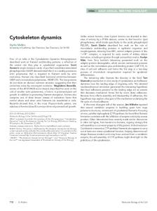
FIG. 1 (color). (a) Proposed indirect drive configuration with multiple Z-pinch soft x-ray sources surrounding a secondary hohlraum. A transparent mesh magnetically isolates each compact Z pinch, and a tailored shine shield geometry symmetrizes the radiation temperature surrounding the ICF fuel capsule in the secondary hohlraum. (b) A planar wire array, here fielded on the Saturn pulsed power facility, is a candidate compact Z-pinch source for driving each low-surface-area primary hohlraum.
125001-1
Ó 2010 The American Physical Society
PHYSICAL REVIEW LETTERS
PRL 104, 125001 (2010)
400 300
4
200 2
100 0
0 0
40 Time (ns)
16 12 8 4
Power (TW)
6
Energy (kJ)
Load current (MA)
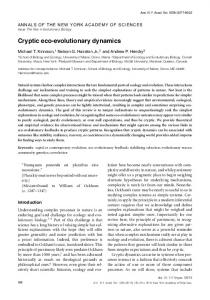
power required of the compact source, which may be any type of load, may be less than that produced to date by optimized cylindrical wire arrays provided a compensating reduction in hohlraum surface area is achieved. The yield in the main x-ray pulse is also an important parameter for driving an ICF capsule. One candidate compact Z-pinch configuration is the planar wire array [Fig. 1(b)], which has demonstrated comparable radiation output to cylindrical arrays at the 1 MA Zebra facility [7,8]. Driving four parallel sources on Z would couple 5–6 MA per Z pinch. In this Letter, we present the first study of the scaling of planar wire-array implosions to multi-MA currents (3–6 MA) on the Saturn pulsed power driver, and combine these experiments with Zebra data to assess x-ray power and yield scaling from 1– 6 MA. An attractive aspect of the multipinch hohlraum drive concept is that experiments with one compact source on lower current facilities may be directly relevant for assessing the performance of each individual source in a multipinch experiment on a higher current facility. Thus, we conclude with a preliminary look at a multipinch concept for the recently refurbished Z machine [9] based on the Saturn scaling results. All Saturn experiments discussed here employed 20 mm tall tungsten arrays with 0.5 mm interwire gaps and a return-current cage with 18 mm � 40 mm rectangular cross section. Figure 2 shows load current and total x-ray power from a 12-mm-wide, 24-wire, 2 mg=cm planar wire array using 23:5 �m diameter wire and fielded on Saturn in short-pulse mode. Radiated yield in excess of estimated kinetic energy has been observed for cylindrical wire arrays [10,11], and here we address this issue for planar arrays. The integral of the x-ray power was compared to the j � B-coupled energy calculated by solving the equations of motion for the wires in the array, treating each as a current filament in a self-consistent global magnetic field [12]. Inductive distribution of the measured load current was assumed between the wires, but resistive (uniform)
0
80
FIG. 2 (color). Load current (red) and total x-ray power (blue) from Saturn shot 3746, a 12-mm-wide, 2 mg=cm planar tungsten wire array. Integral of the x-ray power (solid green) shows yield in excess of calculated j � B-coupled energy with 50% of initial mass participating in the implosion and final radius of 500 �m (dashed) or 150 �m (dash-dotted). A calculation with 500 �m final radius and 100% mass participation (dotted) implodes 15 ns later than observed, suggesting mass trails behind in the implosion.
week ending 26 MARCH 2010
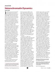
distribution was also considered and found to change the calculated coupled energy by an average of only 10%. This calculation accounts for kinetic energy coupled during the implosion only to the point where a specified final radius is reached, and does not include Ohmic heating or poststagnation heating due to PdV or j � B work on trailing mass. Using a final pinch radius of 500 �m (consistent with pinhole camera data) or even 150 �m (the smallest pinch size consistent with an energy-balance electrical analysis [13] of a separate Saturn planar array including a voltage probe), the calculated j � B-coupled energy is seen in Fig. 2 to be insufficient to explain the x-ray yield. This suggests significant resistive or other heating in multiMA planar wire arrays, as has been suggested for previous 1 MA experiments [7]. Planar wire arrays may also be affected by trailing mass, as in cylindrical array experiments [14]. Matching the measured implosion time typically required �50% mass participation in the calculated implosion (Fig. 2), suggesting that a significant fraction of mass was left behind or trailing. Pinhole images at 277 eV (not shown) revealed a diffuse glow extending to the initial position of the planar array at the time of peak x-ray power. Unlike cylindrical arrays [15], planar arrays have no azimuthal path for current shunting, and the load current must follow (or somehow shunt across) magnetic Rayleigh-Taylor (MRT) bubbles at the implosion front. This may exacerbate trailing mass in planar wire arrays, however the implosion may still be effectively snowplow stabilized by the distributed wire material. Figure 3(a) shows 1-ns-gated composite 277 eV and >1 keV imaging [16] of the Saturn shot described in Fig. 2. An unstable implosion front is seen in frames from �19 to �6 ns, radiating brightly in both photon energy ranges suggesting elevated temperature and density at the shock front associated with MRT bubbles [17]. These bright regions are not generally correlated from right to left across each image. Emission at 277 eV due to ablated or coronal wire plasma is seen interior to the array. A minimum radius is reached at or just before the time of peak x-ray power and corresponds to a peak in >1 keV power, perhaps as kinetic energy is thermalized. A series of 7–10 bright spots of �1 mm scale length are seen along the viewable pinch, which then broaden into an axially striated column that was seen on multiple shots to persist for tens of nanoseconds. The position of the 277-eV implosion front is plotted along the plane of the wire array in Fig. 3(b). Assuming no rapid acceleration in the final stage of implosion, a linear fit gives an implosion velocity of 16 � 2 cm=�s. If 50% of the initial mass participated in this implosion, then the corresponding kinetic energy was 25 � 5 kJ; assuming 100% mass participation gives 50 � 10 kJ, still below the measured 230 kJ main pulse yield (to the back of the FWHM) and 310 kJ total yield. This analysis suggests that resistive heating, compressional or poststagnation j � B work plays a role in planar wire-array dynamics. An electrical analysis [13] of a separate shot on
125001-2
-19 ns
-15 ns
-12 ns
-9 ns
-6 ns
-3 ns
0 ns
+3 ns
5 0
(b)
1 Mass (mg/cm)
10
Total yield Main pulse To peak Foot
10 15 20 Width (mm)
5
5 0 5 -5 0 5 -5 0 5 -5 0 x (mm) x (mm) x (mm) x (mm)
(b) 6
16
16
4
12
±2
cm
/µs
2
PCD >1 keV (arb.)
0
8 4 0
-40
-30 -20 -10 0 10 Time relative to peak x-ray power (ns)
FIG. 3 (color). (a) Imaging of 277 eV self-emission (red) overlayed with >1 keV emission (green, yellow when overlayed with red) timed within 1 ns, showing the planar array implosion from Saturn shot 3746. (b) A linear fit (red) to the trajectory from 277 eV imaging (black points) indicates 16 � 2 cm=�s implosion velocity with stagnation occurring just before peak total x-ray power (blue) and corresponding to a peak in >1 keV emission (gray).
which a voltage probe was fielded gave a lower bound of 0:3 � 0:05 � current averaged pinch resistance on the fall of the x-ray pulse. This result was obtained assuming no current loss between the load measurement point and the pinch. While resistive heating is desirable for a compact x-ray source that must not rely purely on kinetic energy coupling, dedicated diagnostics would be necessary to discern between high pinch resistance and current loss, and the mechanisms originating either remain to be studied. Saturn long-pulse experiments extended the parameter range studied. In Fig. 4(a), the mass of 20-mm-wide planar arrays was varied so that implosion time ranged from 80– 175 ns. The peak power in this scan was 12 TW at 2.8 MA and 96 ns implosion time observed from a 0:5 mg=cm planar array (160 kJ main pulse yield). In Fig. 4(b), mass was varied to keep implosion time fixed at �125 ns while the array width was varied; reducing the initial width to 12 mm reduced peak x-ray power to 8 TW (110 kJ main pulse), and 8 mm width produced 5 TW (70 kJ main pulse). In all cases, a comparison of j � B-coupled energy calculated per Ref. [12] at 150 or 500 �m final radius cannot explain the total radiated yield, nor the main pulse yield in most cases, though it is similar to the yield to peak x-ray power.
FIG. 4 (color). (a) Mass (and implosion time) scan for 20-mmwide planar arrays, and (b) width scan for planar arrays with mass chosen for �125 ns implosion time. The tops of the colored bars indicate total yield (red), main pulse yield (orange), yield to peak power (yellow), and yield in the pulse foot (green). Calculated j � B-coupled energy for neither 500 �m (points connected by solid line) nor 150 �m (dotted line) final radius can generally explain the radiated power in the main peak.
A combined set of �1 MA Zebra, �3 MA Saturn long pulse, and �6 MA Saturn short-pulse experiments is used in Fig. 5 to study radiation scaling per Stygar et al. [18]. In an ideal, self-similar implosion, x-ray yield scales as the square of peak load current (I), proportional to the j � B-coupled energy. Main pulse yield at 8 and 12 mm initial planar array widths is plotted versus I in Fig. 5(a), and is seen to scale slower than quadratic with current ( / I � , � < 2). Scaling fits to total yield and yield to peak power give ranges of � overlapping that for main pulse yield. In Fig. 5(b), x-ray power (P, TW=cm) is plotted versus I 2 divided by implosion time (�), proportional to kinetic energy per time. Fitting P / ðI2 =�Þ� gives a best-fit exponent � < 1, while a value of unity would be expected for an ideal Z pinch [18]. More complete scaling relations (Table I) can be obtained through multivariate least-squares fitting to a set of 20 Saturn and Zebra planar array shots, including the previously discussed scans over mass and implosion time, width (W), and current. The peak power as well as yields (E, kJ=cm) are seen to vary more slowly than I 2 , the ideal scaling for self-similar implosions. The scaling of power with current is identical within error bars to the P / I1:24�0:18 observed by Stygar et al. [18] for cylindrical 100
10
(a)
α= 1.70 ± 0.11 1.87 ± 0.08 1 10 Current (MA)
X-ray power (TW/cm)
0 -5
x (mm)
500 400 (a) 300 200 100 0 0.1
Main pulse yield (kJ/cm)
z (mm)
10
Total x-ray power (TW)
z (mm)
(a) 10
week ending 26 MARCH 2010
PHYSICAL REVIEW LETTERS Energy (kJ)
PRL 104, 125001 (2010)
10 (b)
β= 0.66 ± 0.07 0.71 ± 0.08
1
10 2
100 /τ (MA2/µs)
FIG. 5 (color). (a) Main pulse yield scaling versus peak load current, and (b) peak x-ray power scaling versus I 2 =� using data from Saturn and Zebra generators. Planar array widths of 8 mm (blue) and 12 mm (red) were studied on both machines, and bestfit exponents for yield / I� and power / ðI 2 =�Þ� are indicated.
125001-3
PHYSICAL REVIEW LETTERS
PRL 104, 125001 (2010)
TABLE I. Scaling of planar array power and yield / I� W � �� . P Etotal Emain pulse Epeak
�
�
�
1:28 � 0:13 1:71 � 0:15 1:68 � 0:12 1:78 � 0:16
0:96 � 0:24 0:45 � 0:27 0:64 � 0:21 0:77 � 0:28
�0:64 � 0:12 0:30 � 0:13 0:07 � 0:10 �0:17 � 0:14
tungsten wire arrays on Z. The mass for the planar arrays on Saturn at 6 MA were of order cylindrical wire-array masses on the 20 MA Z machine (1–6 mg), and both types of arrays may be affected by wire ablation physics. Explaining these scalings for planar as well as cylindrical wire arrays is a topic of continuing study and may involve more complete understanding of plasma energy deposition, including resistive effects [13,19], viscous heating [20], or dissipation of magnetic energy [21] in these magnetohydrodynamically unstable plasmas. This study has provided an empirical scaling assessment including load conditions very close to what we would expect to obtain in multisource hohlraum experiments on the Z machine. Guided by this scaling, we now consider the configuration of Fig. 1(a) housing a 2 mm diameter capsule and estimate its performance on Z. We apply the scaling relations of Table I and Fig. 5 assuming no variation of peak power with pinch height, although this dependence remains to be studied. Here we take a set of four planar wire-array soft x-ray sources of 12 mm initial width, 110 ns implosion time, 6 MA load current per Z pinch, and radiating 12 TW each (scaled from the Saturn shots discussed in the text). Static analysis with the VISRAD 3D viewfactor code [22] using albedo values of 0.8 on all wall surfaces and assuming 100% mesh transparency suggests that this configuration will produce Trad � 90 eV at the capsule surface. This is comparable to the highest temperatures obtained in prior indirect drive Z experiments employing cylindrical wire arrays driving a secondary from a single side [23] except here with drive symmetry. The shine shield structure shown in Fig. 1(a) provides