ICIT 2015 The 7th International Conference on Information Technology doi:10.15849/icit.2015.0098 © ICIT 2015 (http://icit.zuj.edu.jo/ICIT15)
Plane Segmentation of Kinect Point Clouds using RANSAC Rifat Kurban
Florenc Skuka
Dept. of Computer Engineering Erciyes University Kayseri, Turkey
[email protected]
Dept. of Computer Engineering Erciyes University Kayseri, Turkey
[email protected]
Hakki Bozpolat Informatics and Inf. Security Research Center TUBITAK Gebze, Turkey
[email protected]
Abstract—In this paper segmentation of planes in point cloud data generated by Microsoft Kinect is detected by using RANSAC method. Two experimental data are acquired by OpenNI and OpenCV library. Kinect camera is first calibrated and the holes in the acquired data are filled. Then, the data is filtered, downsampled and segmented via Point Cloud Library (PCL). Distance threshold and normal weighted distance parameters of RANSAC algorithm are evaluated in the experiments. Keywords—plane segmentation, Kinect, point cloud library
I.
INTRODUCTION
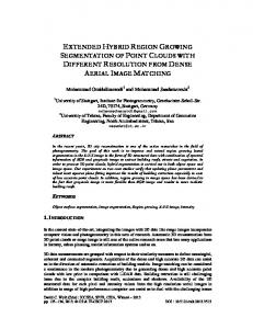
In the last few years three dimensional point cloud processing has become an exciting and very hot research topic in computer vision. Compared to 2D data, range images have several advantages such as 3D geometry processing, 3D shape matching and modeling, feature extraction and matching, segmentation, and object recognition [1]. All these advantages in point cloud data processing are capturing the attention of developers and researchers to develop 3D based applications [4] in many computer vision fields, such as: extracting the user silhouette [4] people detecting and tracking [2], 3D human body modeling and shape analyzing, especially for virtual shopping and clothing industry [3], 3D sensing of the environment representations [5] etc. Recent years many mobile robots have been developed to help people in their works. In order to help humans in their life, first of all, a robot has to percept environments as it is in 3D after that it can process the data according to the job that it has to do. In 3D model environments flat surfaces are really common, as well as to their attractive geometric properties, therefore plane segmentation in such environments is an essential task. In computer vision one of the common algorithms for detecting planes is Random Sample Consensus (RANSAC) [6] which consists to search for the best plane among the point cloud data. Providing depth data with low-cost is made able by last developed sensors such as Microsoft Kinect and Asus Xtion PRO. In [9] a plane detection method in point cloud data is proposed, which detect planes by integrating RANSAC method and minimum description length (MDL). This method can avoid detecting wrong planes in point clouds with complex geometry. It follows these steps to detect planes: It divides point cloud in small rectangles block, in each block applies RANSAC for detecting all planes, and then MDL is used to decide how many planes are in each divided block.
Different versions of the Hough Transform [11] to detect planes in 3D point cloud data are evaluated [10]. An accumulator design to achieve the same size per each cell is presented. This method gives good results when Randomized Hough Transform is applied on 3D data. Because, removing all points which lie on the detected plane, increase the performance for detecting next plan. Moreover, the outcomes show that detecting the underlying structures on the search space is preferred as it can be useful to detect large planes. In [12] a real-time plane detection method based on depth map from Microsoft Kinect sensor is proposed. A system to detect multiple planes fast and roughly in point cloud data acquired from Kinect is suggested. In order to achieve good results for fast detecting multiple planes in 3D point cloud data, they compute local normal vectors of whole point cloud data and classify points in different planes using these local normal vectors. This method has execution time of 2ms and error of 1~2mm levels also shows that it is faster than 3D Hough Transform and RANSAC for plane detection and works in real time. A plane detection method for image sequences acquired from Kinect sensor is presented in [13]. Image sequences rather than a single image like other methods, which provide higher accuracy and robustness results, are used. This method considers the limitation of the depth sensor by using visual data to help detecting planes. Dealing with sequence of images helps accuracy and gives odometer information. II.
DATA ACQUISITION
Data acquisition includes both hardware and software systems. There are many types of hardware (depth sensors) such as: stereo vision camera, 3D time of light sensor structure light based camera [8], which can capture depth data in different environments. Software system is needed for processing the data to be functionally meaningful information. Transformation of the data to the required model for an
Page | 545
ICIT 2015 The 7th International Conference on Information Technology doi:10.15849/icit.2015.0098 © ICIT 2015 (http://icit.zuj.edu.jo/ICIT15)
application needs to pass through some steps: data filtering, data registration and integration, surface reconstruction, data simplification and smoothing, feature detection, data segmentation and data compression [7]. Several techniques are used to acquire depth images. By using just RGB camera it is able to reconstruct 3D environment, however this method requires significant amount of post-processing [8]. Another way for acquiring 3D data is using laser scanning, but this device’s cost is high. Recently low-cost depth sensors such as Microsoft Kinect and Asus Xtion have become widely available and compared to stereo cameras the quality of depth data has been improved. Microsoft Kinect sensor can acquire depth data in lightless environments. Kinect camera was first release by Microsoft on November, 2010 as it can be seen in Fig.1. Microsoft Kinect sensor contains two cameras and one laser-based IR projector. It is able to produce 640x480 pixels 32 - bit color images and 320x240 pixels 16-bit depth images both at 30 frames per second. Depth images are provided by projecting light patterns on the surrounding scene, IR camera receives the reflected light and compare their positions with the reference pattern [4]. Mostly Kinect has advantages but has some disadvantages too like limitation in detection, Kinect cannot acquire depth image in distance les then 50 cm and more than 10 m, but in order to get good precision we take into consideration data in the range of 0.5 meters up to 8 meters. Also due to the occlusion of IR projection in depth images there are some missing regions, non-measured depth pixel [13]. Another disadvantage of Kinect is that it cannot acquire depth images under sunlight. In order to improve the quality of depth images, acquired data should pass through some filters. In this work as input source for data acquiring we adopt Microsoft Kinect Sensor with OpenNI (Open Natural Interaction) driver [15] which enables communication with RGB and depth cameras of Kinect, and OpenCV (Open Source Computer Vision) library [16] which is used for processing depth images. OpenNI is an open source multi-langue, cross-platform framework which provides an application programming interface for writing applications utilizing natural interaction. OpenCV is open source library that supports different applications in computer vision. Moreover it is free for both commercial and non-commercial use. This library has different interfaces such as: C, C++, Java and Python, it also supports Windows, Linux, Mac OS, iOS and Android.
III.
POINT CLOUD DATA PROCESSING
To achieve robust results from data provided by Microsoft Kinect sensor it is very necessary to apply some operations on these raw data. In Fig 2., the way how to process with point cloud data is shown.
Fig. 2. Flow Chart of Point Cloud Processing For Plane Segmentation.
Camera calibration is a necessary step in computer vision for tasks such as 3D reconstruction. The camera calibration procedure consists of estimating intrinsic parameters, extrinsic parameters and distortion coefficients. Intrinsic parameters consist of camera focal length, and principal point, whereas extrinsic parameters stands for rotation (R) matrix and translation vector (t) of the sensor with respect to the world coordinate system. Distortion coefficients are the coefficients from the radial and tangential distortion. Hole filling, is needed due to the occlusion of IR projection, acquired depth images have some non-measured depth pixels. Before working with such data it is necessary to fill these holes. Depth to point cloud is used for transforming a depth images to point cloud data. This can be done by using IR camera intrinsic parameters, focal length and principal point. The algorithm for converting depth images to point cloud data is as following: Algorithm 1: Depth To Point Cloud 1: factor = 1000; //Meter to MM 2: for v=1 to height 3: for u=1 to width 4: z = depth(v,u) / factor; 5: x = (u - cx_d) * z / fx_d; 6: y = (v - cy_d) * z / fy_d; 7: pcloud(v,u,1)=x; 8: pcloud(v,u,2)=y; 9: pcloud(v,u,3)=z; 10: end 11: end
Fig. 1. Microsoft Kinect Sensor v1.
where fx_d, fy_d are the focal length and cx_d, cy_d are the principal points.
Page | 546
ICIT 2015 The 7th International Conference on Information Technology doi:10.15849/icit.2015.0098 © ICIT 2015 (http://icit.zuj.edu.jo/ICIT15)
Removing Non-measured Pixels is needed because even if some filters are applied for filling holes in point cloud we can see that not always the whole holes are filled. This depends on the size of nmp (non measured pixels) in point cloud. In order to prevent these non measured pixels effecting negatively the results, removing these nmp pixels is necessary. Furthermore removing nmp changes the structure of point cloud from organized to unorganized. In the same time, removing the nmp will change the size of the point, and in the unorganized point cloud data the height is set to 1 and width size is the rest of the points. Removing Noise, decreases unwanted points from raw data provided by Kinect. For robust processing of point cloud data it is important and necessary to apply some filters for removing noise and outliers out of the original point cloud data because they can effect and produce errors in processing. As a result the point cloud data is classified as inlier point and outlier points. After filtering, point cloud data contains just inlier points. Moreover removing outliers from point cloud decrease the processing time as well as downsampling.
(length(s) = bestSupport and st < bestStd) then 12: bestSupport = length(s) 13: bestPlane = pl; bestStd = st 14: end if 15: i = i + 1 16: end while
IV.
EXPERIMENTAL RESULTS
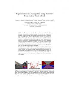
In this work as input source for data acquiring we adopt Microsoft Kinect Sensor with OpenNI (Open Natural Interaction) driver which enables communication with RGB and depth cameras of Kinect, and OpenCV (Open Source Computer Vision) library is used for processing depth images. Data acquisition is done by capturing data from two different scenes, Office Data and Corridor Data as shown in Fig. 3.
Downsampling, also reduces the amount of points. Microsoft Kinect sensor produces a point cloud containing 307200 (640x480) points. Working with such high resolution point clouds for detection planes requires a lot of processing time. In order to decrease the process time of detection planes in point cloud data applying some optimization techniques such as Voxel Grid Downsampling filter is required. Setting parameters in efficient way to voxel grid filter will yield very good results also will reduce execution time and cost of the CPU power. Plane segmentation, is the final step. After point cloud data is processed RANSAC based plane fitting method is applied to detect planes in point cloud data robustly. RANSAC method finds the largest set of points that fit to plane. The plane equation in three dimensional point cloud data can be defined as:
ax + by +cz + d=0
(b)
(a)
Fig. 3. Original Data Captured by Kinect .(a) Corridor Data, (b) Office Data
A. Camera Calibration IR camera intrinsic and extrinsic parameters are estimated using Zhang’s calibration method [14] and traditional known structure chessboard pattern is used as calibration object as shown in Fig.4, containing 10x7=70 corners, and each square is size of 25.5 mm
(1)
Where a, b and c are plane parameters and d is distance of plane from the origin. RANSAC selects randomly three points from dataset and calculates the parameters of the corresponding plane, after that tries to enlarge the plane according to a given threshold, [17]. Algorithm 2: Ransac 1: bestSupport = 0; bestPlane(3,1) = [0, 0, 0] 2: bestStd = ∞; i = 0 3: ε = 1 - forseeable-support/length(point-list) 4: N = round(log(1 -α)/log(1 - (1-ε)3)) 5: while i ≤ N do 6: j = pick 3 points randomly among (point-list) 7: pl = pts2plane(j) 8: dis = dist2plane(pl, point-list) 9: s = find(abs(dis) ≤ t) 10: st = Standard-deviation(s) 11: if (length(s) > bestSupport) or
(a)
(b)
Fig. 4. Camera calibration: (a) chessboard pattern, (b) detected corners.
In Table I and Table II focal length, principal point and distortion coefficients are shown respectively after camera calibration process is done. TABLE I.
fx
FOCAL LENGTH AND PRINCIPAL POINT
fy
cx
cy
Page | 547
ICIT 2015 The 7th International Conference on Information Technology doi:10.15849/icit.2015.0098 © ICIT 2015 (http://icit.zuj.edu.jo/ICIT15)
582.74107
582.74107
TABLE II.
319.5
243.5
DISTORTION COEFFICIENTS
k1
k2
p1
p2
k3
0
0
0
0
0
B. Hole filling Two methods are implemented for filling holes. In the first one, as shown in Fig.5, holes are filled by using 10 depth images captured of the same scene without changing the camera view orientation. For 10 depth images average of each pixel is calculated to get the new depth image. The non measured pixels are not taken into calculation.
(a)
(b)
(a)
(b)
Fig. 7. Converting depth image to point cloud data, (a) Depth Image, (b) Point Cloud Data
D. Removing Non-measured Pixels The last remaining non-measured pixels are removed from depth image by applying removeNaNFromPointCloud filter which is implemented on PCL (Point Cloud Library) [18] E. Removing Noise Noise is removed using PCL by applying StatisticalOutlierRemoval filter as shown in Fig.8. The best result was achieved by passing these parameters to filter for neighborhood size k=50 and 2.5*distance from the mean distance .
Fig. 5. First method of hole filling, (a) Original Depth images captured by Microsoft Kinect, (b) the resultant filtered depth image using first method
In the second method as shown in Fig.6, 3x3 Median Filter is applied on the resultant image of the first method. By applying such filters on images edge information is lost. However such information is not important to detect plane, applying this filter on depth images does not affects negatively the plane segmentation results.
(a)
(b)
Fig. 6. Second method of hole filling, (a) Left: The resultant filtred depth image with first method,(b) resultant median filtered depth image
C. Depth to point cloud As it is seen from IR camera calibration results the distortion coefficients are zero. This is because acquiring data using OpenNI driver with Microsoft Kinect sensor returns a processed image. Due to zero distortion it is not necessary to undistort depth images before converting to point cloud data. The depth data acquired from Kinect using OpenNI driver is in the form of 16-bit 2-D intensity image. Transforming a depth image to point cloud data as shown in Fig.7 using IR camera intrinsic parameters, the focal length and the principal point are required
(a)
(b)
(c) Fig. 8. An example of applying StatisticalOutlierRemoval filter to point cloud data. (a) point cloud data, (b) point cloud data after StatisticalOutlierRemoval operator is applied, (c) nois of point cloud data (outlier).
F. Downsampling After data is filtered, in order to decrease the process time of plane segmentation voxel grid filter is applied. The size of every voxel is set to 1x1x1cm. Microsoft Kinect sensor produces a depth image with the size of 640x480=307200 points. This is the initial size of point cloud data if no filter is used. Working with such high resolution point clouds for detection planes requires a lot of processing time. The size of point cloud data after applying all filters is reduced to 73515 points, approximately 24% of the original
Page | 548
ICIT 2015 The 7th International Conference on Information Technology doi:10.15849/icit.2015.0098 © ICIT 2015 (http://icit.zuj.edu.jo/ICIT15)
data. Reducing the size of point cloud data without losing necessary information will yield very good results also will reduce execution time and cost of CPU power.
RANSAC algorithm implemented on PCL is used for detecting the largest plane. The size of neighborhood k for estimating point normals is chosen 50, Also maximum iteration size equal is chosen as 100. The algorithm is run several times for each data by changing the values of NormalDistanceWeight and DistanceThreshold parameters. Evaluation parameter values for the algorithm are as follow: Normal Distance Weight ={0.001, 0.01, 0.1, 1} and DistanceThreshold ={0.01, 0.05, 0.1,0.5}.
(a)
(b)
Fig. 9. The result of voxel grid filter. (a) Original data, (b) downsampled data
G. Plane Detection Plane detection algorithm receives the processed point cloud data as input. Therefore, after all necessary operations are done on point cloud data both data Office Data and Corridor Data are tested by changing the values of input parameter of the algorithm. TABLE III.
In total, the algorithm is run 16 times for each data. The best result for Office Data was achieved when NormalDistanceWeight =0.01 and DistanceThreshold =0.1. Whereas the best result for Corridor Data was achieved when NormalDistanceWeight = 0.001 and DistanceThreshold =0.1 As it can be observed from results, for different point cloud data different parameter values have to be used in order to get the best results.
RESULTS OF PLANE SEGMENTATION FOR CORRIDOR DATA
Distance Threshold 0.05
0.1
0.5
0.01 0.1
Normal Weighted Distance
0.001
0.01
Page | 549
ICIT 2015 The 7th International Conference on Information Technology
1
doi:10.15849/icit.2015.0098 © ICIT 2015 (http://icit.zuj.edu.jo/ICIT15)
TABLE IV.
RESULTS OF PLANE SEGMENTATION FOR OFFICE DATA
Distance Threshold 0.05
0.1
0.5
0.01 0.1 1
Normal Weighted Distance
0.001
0.01
V.
CONCLUSION AND FUTURE WORKS
In this paper an efficient way of data processing and evaluation of distance threshold and normal weighted
distance parameters for plane detection using RANSAC algorithm is presented. Applying different operations on point cloud data such as hole filling, removing non-measured pixels, removing noise and downsampling the data before
Page | 550
ICIT 2015 The 7th International Conference on Information Technology doi:10.15849/icit.2015.0098 © ICIT 2015 (http://icit.zuj.edu.jo/ICIT15)
trying to detect the plane yields very good results also reduces execution time and the cost of the CPU power.
Lidar Data”, The photogrammetric journal of Finland, 2008, 21 (1), pp.97-109. [18] PCL,http://pointclouds.org/, (Online; Accessed: 04 February 2015)
From the experimental results it is shown that for different data, different parameter values are needed to get the best results. As a future work, an adaptive method for parameter estimation based on the input point cloud data to achieve robust result is planned. ACKNOWLEDGEMENTS The authors would like to thank Research Foundation of the Erciyes University, Kayseri, Turkey for supporting this work under the Grant No. FYL-2015-5601. REFERENCES [1]
[2]
[3] [4]
[5]
[6]
[7]
[8]
[9] [10]
[11] [12]
[13]
[14]
[15] [16] [17]
Y. Guo, M. Bennamoun, F. Sohel, M. Lu, and J. Wan, "3D Object Recognition in Cluttered Scenes with Local Surface Features: A Survey", IEEE Transactions On Pattern Analysis And Machine Intelligence, 2013, pp:2270-2287. M. Munaro, F. Basso and E. Menegatti, "Tracking people within groups with RGB-D data", 2012 IEEE/RSJ International Conference on, Intelligent Robots and Systems, 2012, Portugal. I. Douros and B.F. Buxton, "Three-Dimensional Surface Curvature Estimation using Quadric Surface Patches". Proc. intern. symp., 2002. M. Camplani, T. Mantecón, and L. Salgado, “Depth-Color Fusion Strategy for 3-D Scene Modeling With Kinect” IEEE Transactions On Cybernetics, 2013, 43, 6, pp:1560-1571. F. Endres, J. Hess, N. Engelhard,J. Sturm, D. Cremers, and W. Burgard, "An Evaluation of the RGB-D SLAM System" 2012 IEEE International Conference on Robotics and Automation,RiverCentre, 2012, Saint Paul, Minnesota, USA, pp:1691:1696. M.A. Fischler and R.C. Bolles. “Random sample consensus: A paradigm for model fitting with applications to image analysis and automated cartography”. Communications of the ACM, 1981, 24(6): pp 381–395. Z.M. Bi and L. Wangb, "Advances in 3D data acquisition and processing for industrial applications" Robotics and ComputerIntegrated Manufacturing 26(2010), pp:403–413. S. Paulus, J. Behmann, A. K. Mahlein, L. Plümer, and H. Kuhlmann, "Low-Cost 3D Systems: Suitable Tools for Plant Phenotyping", Sensors 2014, 14, pp:3001-3018. M. Y. Yang, and W. Förstner, "Plane Detection in Point Cloud Data" TR-IGG-P-2010-01,January 25, 2010 D. Borrmann, J. Elseberg, K. Lingemann, and A. Nüchter, "The 3D Hough Transform for Plane Detection in Point Clouds: A Review and a new Accumulator Design" 3D Research, pp:1-13. H. Paul V C, “Method and Means for Recognizing Complex Patterns,” U.S. Patent No. 3069654, 1962. H. Woo Yoo, W. Hyun Kim, J. Woo Park, W. Hyong Lee, and M. Jin Chung, "Real-Time Plane Detection Based on Depth Map from Kinect", 2013, 44th International Symposium on Robotics (ISR). Y. Suttasupa, A. Sudsang and N. Niparnan "Plane Detection for Kinect Image Sequences", Proceedings of the 2011 IEEE, International Conference on Robotics and Biomimetics, December 711, 2011, Phuket, Thailand Z. Zhang, “A flexible new technique for camera calibration”,IEEE Transactions On Pattern Analysis And Machine Intelligence, VOL. 22, NO. 11, November 2000 OpenNI,https://github.com/OpenNI/OpenNI, (Online; Accessed: 04 February 2015) OpenCV,http://opencv.org/, (Online; Accessed: 04 February 2015) F. Tarsha-Kurdi, T. Landes, and P. Grussenmeyer, “Extended Ransac Algorithm For Automatic Detection Of Building Roof Planes From
Page | 551