feasibility and cost of replacing fixed-route transit with Flex-Route service; and developing a .... 4.4.5 DISPATCH CENTRE. 141 ...... To address the needs of decision-makers in this field, there is a need for detailed guidelines to help transit ...
PLANNING, DESIGN AND SCHEDULING OF FLEX-ROUTE TRANSIT SERVICE
BY
BAHA W. ALSHALALFAH
A thesis submitted in conformity with the requirements for the degree of Doctor of Philosophy Graduate Department of Civil Engineering University of Toronto
© Copyright by Baha W. Alshalalfah (2009)
ii Planning, Design and Scheduling of Flex-Route Transit Service Baha W. Alshalalfah Doctor of Philosophy Department of Civil Engineering University of Toronto 2009
ABSTRACT The rapid expansion of low-density suburban areas in North America has led to new travel patterns that require transit services to be more flexible. Flex-Route transit service, which combines fixed-route transit service with elements of demand-responsive transit service, has emerged as a viable transit option to address the travel needs of the residents of these areas. Existing literature in this field, however, is limited and lacks any comprehensive analysis of Flex-Route planning, design and scheduling. This research aims at exploring Flex-Route transit service to provide detailed guidelines for the planning and design of the service, as well as developing a new scheduling system for this type of unique service. Accordingly, the objectives of this research are: assessing the practicality of Flex-Route transit service in serving low-density suburban areas; identifying essential Flex-Route planning steps and design parameters; determining the feasibility and cost of replacing fixed-route transit with Flex-Route service; and developing a Flex-Route-specific dynamic scheduling system that relies on recent developments in computer and communication technologies. In this regard, we develop an analytical model that addresses several design parameters and provide a detailed analysis that includes, among other parameters, finding optimal values for Flex-Route service area and slack time. Furthermore, the analytical model includes a feasibility and cost analysis that estimates the cost incurred by several stakeholders if Flex-Route service is chosen to replace fixed-route service. The core of the scheduling system is a new developed algorithm – the ConstrainedInsertion Algorithm- that exploits the powerful search techniques of Constraint Programming. The scheduling system can handle the daily operations of Flex-Route transit
iii services; it accepts daily (or dynamic) inputs and, in minimal time, produces very costeffective and reliable schedules. Moreover, the scheduling system has the ability to be used as simulation tool to allow transit operators to assess the feasibility and performance of proposed Flex-Route transit services before implementation. The applicability of the analytical model as well as the performance of the scheduling system were subsequently evaluated and validated through process that included testing on a case study in the City of Oakville, Canada.
iv
ACKNOWLEDGEMENTS A journey that started in occupied Palestine and saw me get through so many ups and downs during my Masters and PhD studies, now finds me trying, in few words, to thank every person who helped me through this journey. It won’t be easy, but I’ll try my best. First, special thanks to Prof. Amer Shalaby for his advice, guidance, and genuine support. His open-mindedness, dedication and humility are examples to be followed. It was a great honour for me to get to know him and learn from him over the past six years. Many thanks to the members of my examination committee: Prof. Eric Miller, Prof. Baher Abdulhai and Prof. Matthew Roorda, for their valuable comments on my thesis and for all their guidance and support throughout my PhD studies. I am also thankful to Prof. Nigel Wilson for agreeing to be the external examiner of my thesis, and also for his valuable feedback and comments. Special thanks to Hani Qaddumi Scholarship Foundation for their generous funding of my Masters studies, which paved the way for me to get this PhD. To my brothers and sisters (Sana’, Yousef, Mohammed, Alaa’ and Suhair) and their families (especially the little ones): I can’t thank you enough for all your support and love. You always stood beside me, supported me and believed in me. I love you all. To my father, who is no longer with us on this earth but lives in our hearts: I wish you had the chance to be with us in such joyous moments. Last but not least, to the one person whose devotion, perseverance, dedication and love has no limits; the person who taught me that miracles, like what she did, could happen; the person who always believed in me, and without her prayers I wouldn’t be the person I am today: Mom, I cannot thank you enough for everything you have done and had to go through to see me get this degree.
To the people of Palestine
v
TABLE OF CONTENTS ACKNOWLEDGEMENTS TABLE OF CONTENTS LIST OF FIGURES LIST OF TABLES 1
INTRODUCTION
IV V XI XIII 1
1.1
POINT OF DEPARTURE - MOTIVATING SCENARIO
4
1.2
OBJECTIVES
5
1.3
THESIS SCOPE
7
1.4
LIMITATIONS
11
1.5
THESIS ORGANIZATION
11
2
LITERATURE REVIEW
14
2.1
CHAPTER OVERVIEW
14
2.2
DEMAND-RESPONSIVE TRANSIT
14
2.3
FLEXIBLE TRANSIT SERVICES
19
2.3.1
TYPES OF FLEXIBLE TRANSIT SERVICE
20
2.3.2
FLEXIBLE TRANSIT SERVICE BENEFITS
24
2.4
FLEX-ROUTE TRANSIT SERVICE
25
2.4.1 FLEX-ROUTE TRANSIT SERVICE IN THE LITERATURE 2.4.1.1 Optimal Slack Time (Fu, 2002)
26 26
2.4.1.2
A Multi-objective Optimization Model
29
2.4.1.3
Other Research Efforts
30
2.4.2 FLEX-ROUTE TRANSIT SERVICE IN PRACTICE 2.4.2.1 Madison, Wisconsin
31 31
2.4.2.2
Potomac and Rappahannock Transportation Commission (PRTC), Virginia
31
2.4.2.3
System for Advanced Management of Public Transport Operations (SAMPO)
33
vi 2.4.2.4 2.5
The Mobility Allowance Shuttle Transit (MAST)
ROUTING AND SCHEDULING EFFORTS
34 35
2.5.1
THE DIAL-A-RIDE PROBLEM (DARP)
35
2.5.2
SCHEDULING THE FLEX-ROUTE PROBLEM
39
2.5.3 DYNAMIC VEHICLE ROUTING AND SCHEDULING 2.5.3.1 Adaptation of Static Algorithms
42 43
2.5.3.2
44
2.5.4 2.6 3
Stochastic Methods FLEX-ROUTE TRANSIT SCHEDULING
LIMITATIONS OF EXISTING RESEARCH FLEX-ROUTE PLANNING AND DESIGN PARAMETERS
45 47 49
3.1
CHAPTER OVERVIEW
49
3.2
SUBURBAN TRANSIT SERVICE: CHALLENGES AND OPPORTUNITIES
49
3.3
FLEX-ROUTE SERVICE DESIGN
52
3.3.1 AREA CONFIGURATION 3.3.1.1 Spread-Out Areas
55 55
3.3.1.2
55
Hard-to-Serve Areas
3.3.2 SERVICE CHARACTERISTICS 3.3.2.1 Vehicle route
56 56
3.3.2.2
Boarding and alighting locations
56
3.3.2.3
Schedule
56
3.3.2.4
Advance-notice requirements
57
3.3.3 FLEX-ROUTE SERVICE AREA 3.3.3.1 Two-Sided Service Areas
60 62
3.3.3.2
69
Single-sided service area
3.3.4 SLACK TIME 3.3.4.1 Allocation of Slack Time among Route Segments
73 73
3.3.4.2
78
Slack Time for A Single Route Segment with Known Service Area
3.3.5
FIXED STOP LOCATION AND SPACING
79
3.3.6
SERVICE FREQUENCY
81
3.4
FLEX-ROUTE FEASIBILITY AND COST ANALYSIS
86
3.4.1 OPERATOR COST 3.4.1.1 Same Frequency (Same Headway)
90 90
3.4.1.2
91
Lower Frequency (Increased Headway)
vii 3.4.2 OPERATOR BENEFIT 3.4.2.1 Same Frequency (Same Headway)
92 92
3.4.2.2
93
Lower Frequency (Increased Headway)
3.4.3 FIXED-ROUTE USER COST 3.4.3.1 Same Frequency (Same Headway) 3.4.3.2
Lower Frequency (Increased Headway)
93 94 100
3.4.4 TOTAL ADDITIONAL SYSTEM COST 3.4.4.1 Same Frequency/ Same Number of Fixed Stops
104 104
3.4.4.2
Lower Frequency/ Same Number of Fixed Stops
105
3.4.4.3
Lower Frequency/ Reduced Number of Fixed Stops
105
3.4.5
TOTAL ADDITIONAL SYSTEM BENEFIT
106
3.4.6
STRATEGIES TO MAINTAIN THE LEVEL OF SERVICE FOR FIXED-ROUTE USERS
106
3.5
FLEX-ROUTE PERFORMANCE
113
3.5.1
PASSENGER BOARDINGS PER VEHICLE REVENUE HOUR (PVRH)
114
3.5.2
PASSENGER BOARDINGS PER VEHICLE REVENUE KM (PVRKM)
116
3.5.3
STRATEGIES TO IMPROVE THE PERFORMANCE OF FLEX-ROUTE SERVICE
118
4
REAL-TIME DECISION-SUPPORT AND SCHEDULING SYSTEM FOR FLEX-ROUTE
TRANSIT SERVICES
121
4.1
CHAPTER OVERVIEW
121
4.2
FLEX-ROUTE ROUTING AND SCHEDULING
121
4.3
NEW APPROACH: CONSTRAINT PROGRAMMING
122
4.3.1
ORIGINS OF CONSTRAINT PROGRAMMING
123
4.3.2
FORMULATION
124
4.3.3
CONNECTIONS TO INTEGER PROGRAMMING
125
4.3.4
APPLICATIONS
126
4.3.5 CONSTRAINT PROGRAMMING ALGORITHMS 4.3.5.1 Domain Reduction and Arc Consistency
127 128
4.3.5.2
Constraint Propagation
131
4.3.5.3
Constraint Programming Algorithms for Optimization
136
4.3.5.4
Programming a Search Strategy
137
4.4
PROPOSED DECISION-SUPPORT SYSTEM ARCHITECTURE
138
4.4.1
TRIP RESERVATION
140
4.4.2
ROUTING AND SCHEDULING ALGORITHM
140
viii 4.4.3
GEOGRAPHIC INFORMATION SYSTEM (GIS) PLATFORM
140
4.4.4
MOBILE DATA TERMINALS (MDTS)
141
4.4.5
DISPATCH CENTRE
141
4.5
SCHEDULING METHODOLOGY FOR THE STATIC FLEX-ROUTE PROBLEM
143
4.5.1
SYSTEM CHARACTERISTICS AND ASSUMPTIONS
144
4.5.2
THE STATIC FLEX-ROUTE MODEL
146
4.5.3
STATIC FLEX-ROUTE ROUTING AND SCHEDULING METHODOLOGY
151
4.5.4 BUILD THE PROBLEM MODEL 4.5.4.1 Modeling Objects
153 155
4.5.5
INITIAL SOLUTION: THE CONSTRAINED-ASSIGNMENT ALGORITHM
156
4.5.6
IMPROVE THE SOLUTION USING LOCAL SEARCH
157
NEIGHBORHOODS 4.6
158
SCHEDULING METHODOLOGY FOR THE DYNAMIC FLEX-ROUTE PROBLEM164
4.6.1
DYNAMIC FLEX-ROUTE PROBLEM FEATURES
164
4.6.2
DYNAMIC FLEX-ROUTE PROBLEM MODEL
166
4.6.3
DYNAMIC FLEX-ROUTE MODEL FOR LATE ARRIVAL
170
4.6.4
DYNAMIC FLEX-ROUTE SCHEDULING METHODOLOGY
175
5
MODEL IMPLEMENTATION AND VALIDATION
179
5.1
INTRODUCTION
179
5.2
EVALUATION OF THE SCHEDULING MODEL
179
5.2.1
CASE STUDY ASSUMPTIONS / SETTINGS
181
5.2.2
COMPARATIVE ANALYSIS
182
5.2.3 SENSITIVITY ANALYSIS 5.2.3.1 Time Window Duration
186 186
5.2.3.2
186
Excess Ride Time
5.3
VALIDATION OF THE ANALYTICAL MODEL AND SCHEDULING SYSTEM
190
5.4
SENSITIVITY ANALYSIS
196
5.4.1 EFFECT OF DESIGN PARAMETERS ON THE NUMBER OF FEASIBLE DEVIATIONS 5.4.1.1 Effect of Service Area Width on Feasible Deviations
198 198
5.4.1.2
Effect of Slack Time on Feasible Deviations
199
5.4.1.3
Effect of On-Demand Request Rate on Feasible Deviations
203
5.4.1.4
Effect of Fixed-Stop Spacing on Feasible Deviations
206
5.4.2
DYNAMIC REQUESTS EFFECT AND LATE ARRIVAL
207
ix 5.4.2.1 5.5 6
Effects of Fixed-Stop Spacing on Dynamic Requests Acceptance
CONCLUSIONS CASE STUDY - OAKVILLE TRANSIT
213 216 217
6.1
CHAPTER OVERVIEW
217
6.2
INTRODUCTION AND BACKGROUND
217
6.3
THE GO TRANSIT PARKING PROBLEM
218
6.4
EXPERIMENTAL STUDY SETTINGS
220
6.4.1
EXISTING DESIGN OF THE STUDY’S FIXED ROUTES
221
6.4.2 PROPOSED FLEX-ROUTE SYSTEM: ASSUMPTIONS AND SPECIFICATIONS 6.4.2.1 Fixed-Route
226 226
6.4.2.2
On-demand Service
227
6.4.2.3
General Specifications
229
6.5
ANALYSIS OF DESIGN PARAMETERS
231
6.5.1 EFFECT OF SLACK TIME 6.5.1.1 Route Number 11
231 231
6.5.1.2 Route Number 21
233
6.5.1.3 Route Number 25
234
6.5.2 EFFECT OF ON-DEMAND REQUEST RATE
236
6.6
237
FEASIBILITY ANALYSIS OF THE PROPOSED FLEX-ROUTE SERVICE
6.6.1 SERVICE PROVIDER COST
237
6.6.2 FIXED-ROUTE USER COST 6.6.2.1 Unused Slack Time
239 239
6.6.2.2 Average Travel Time
240
6.6.3
244
6.7 7
FLEX-ROUTE PERFORMANCE VS. FIXED-ROUTE PERFORMANCE SUMMARY AND CONCLUSIONS
CONCLUSIONS AND RECOMMENDATIONS
248 249
7.1
SUMMARY AND CONCLUSIONS
249
7.2
CONTRIBUTIONS
252
7.2.1
DEVELOPING A FLEX-ROUTE ANALYTICAL MODEL
7.2.2
BUILDING A SCHEDULING SYSTEM TO SUPPORT THE OPERATIONS OF FLEX-ROUTE TRANSIT
SERVICE.
252 254
x 7.3
RECOMMENDATIONS FOR FUTURE RESEARCH
255
xi
LIST OF FIGURES Figure 1-1 Scope of the research ............................................................................................ 10 Figure 2-1 Illustration of a typical fixed-route transit line ..................................................... 16 Figure 2-2 Illustration of a typical DRT service..................................................................... 17 Figure 2-3 Flexible transit service categories (Source: Koffman, D. (2004). TCRP, Report 53 ................................................................................................................................................. 22 Figure 2-4 Fu’s Flex-Route service in an ideal network......................................................... 28 Figure 2-5 MAST System....................................................................................................... 41 Figure 3-1 A typical Flex-Route service area ......................................................................... 54 Figure 3-2 T1wo-sided service area of one route segment ..................................................... 65 Figure 3-3 One-sided service area .......................................................................................... 72 Figure 3-4 Cases of (a) different service area width, and (b) fixed stop spacing among route segments.................................................................................................................................. 77 Figure 3-5 Calculation of Average Access Distance for Fixed Route Users.......................... 98 Figure 4-1: Constraint Programming solving procedure ...................................................... 128 Figure 4-2: Constraint propagation and domain reduction are used to reduce the domains of the variables X and Y (source: Lusting and Puget, 2001).................................................... 135 Figure 4-3: A search tree....................................................................................................... 138 Figure 4-4: REFLEX structure.............................................................................................. 142 Figure 4-5: Scheduling Methodology ................................................................................... 154 Figure 4-6: The Two-Opt neighbourhood............................................................................. 161 Figure 4-7: The Or-Opt neighbourhood................................................................................ 162 Figure 4-8: The Relocate neighbourhood ............................................................................. 163 Figure 4-9: The Exchange neighbourhood ........................................................................... 163 Figure 4-10 Bus route in dynamic environment ................................................................... 165 Figure 4-11 Dynamic-request assignment procedure ........................................................... 177 Figure 4-12 Diversion of a transit vehicle in real time ......................................................... 178 Figure 5-1 Effect of time window duration and maximum allowable ride time on percentage reduction in cost: (a) based on 30km\hr vehicle-average-velocity, and (b) based on 20km\hr vehicle-average-velocity. ...................................................................................................... 188 Figure 5-2 Effect of time window duration and maximum allowable ride time on percentage reduction in vehicle used: (a) based on 30km\hr vehicle-average-velocity, and (b) based on 20km\hr vehicle-average-velocity ........................................................................................ 189 Figure 5-3 Map of the hypothetical route for a service area of 500m .................................. 193
xii Figure 5-4: Effect of slack time and service area width on the percentage of accepted ondemand requests for a demand rate of 10 requests /run........................................................ 201 Figure 5-5: Effect of slack time and service area width on the percentage of accepted ondemand requests for a demand rate of 15 requests /run........................................................ 202 Figure 5-6: Effect of on-demand request rate on the percentage of accepted requests for a slack time of 3 minutes ......................................................................................................... 204 Figure 5-7: Effect of on-demand request rate on the percentage of accepted requests for a slack time of 6 minutes ......................................................................................................... 205 Figure 5-8: Effect of fixed-stop spacing on the percentage of accepted requests for a slack time of 6 minutes .................................................................................................................. 207 Figure 6-1 Map of route 11................................................................................................... 223 Figure 6-2 Map of route 21................................................................................................... 224 Figure 6-3 Map of route 25................................................................................................... 225 Figure 6-4 Example of the produced map for route 21 (demand =6/run and slack time = 5min) ..................................................................................................................................... 230 Figure 6-5: Relationship between slack time and the number of accepted requests for Route 11........................................................................................................................................... 232 Figure 6-6: Relationship between slack time and the number of accepted requests for Route 21........................................................................................................................................... 234 Figure 6-7: Relationship between slack time and the number of accepted requests for Route 25........................................................................................................................................... 236 Figure 6-8: Relationship between slack time and the unused slack time for Route 11 ........ 241 Figure 6-9: Relationship between slack time and the unused slack time for Route 21 ........ 241 Figure 6-10: Relationship between slack time and the unused slack time for Route 25 ...... 242 Figure 6-11: Relationship between slack time and the passenger per VRH for Route 11.... 246 Figure 6-12: Relationship between slack time and the passenger per VRH for Route 21.... 247 Figure 6-13: Relationship between slack time and the passenger per VRH for Route 25.... 247
xiii
LIST OF TABLES Table 2-1: Number of transit systems using each type of flexible transit service .................. 23 Table 3-1 Number of transit agencies using flexible services in different suburban areas’ configurations ......................................................................................................................... 58 Table 3-2: Elements of service design for fixed-route, demand-responsive and flexible transit services.................................................................................................................................... 59 Table 3-3: Maximum extent of deviations reported for Flex-Route transit service ............... 61 Table 3-4 Definitions of variables used in the cost-benefit analysis ...................................... 88 Table 5-1: Scheduling Results Obtained for the Cases of 30km/hr Vehicle-Average-Velocity ............................................................................................................................................... 184 Table 5-2: Scheduling Results Obtained for the Cases of 20km/hr Vehicle-Average-Velocity ............................................................................................................................................... 185 Table 5-3: Optimal slack time values for each route segment (in min) for different combinations of service area width and on-demand request rate, using equation 3-22 ....... 195 Table 5-4: Number of accepted requests for combinations of slack time and on-demand request rate for a service area width of 250m (0.25 km) for each route segment, simulation results .................................................................................................................................... 195 Table 5-5: Number of accepted requests for combinations of slack time and on-demand request rate for a service area width of 500m (0.5 km) for each route segment, simulation results .................................................................................................................................... 195 Table 5-6: Number of feasible deviations for 1 Km fixed-stop spacing (8-hour service duration)................................................................................................................................ 197 Table 5-7: Number of feasible deviations for 2 Km fixed-stop spacing (8-hour service duration)................................................................................................................................ 198 Table 5-8: Results obtained for cases 1 to 3 (spacing =1 km). ............................................. 209 Table 5-9: Results obtained for cases 4 to 6 (spacing =1 km) .............................................. 212 Table 5-10: Results obtained for cases 7 to 9 (spacing = 2 km). .......................................... 214 Table 5-11: Results obtained for cases 10 to 12 (spacing = 2 km). ...................................... 215 Table 6-1: Typical parking facility financial costs ............................................................... 220 (Source: Victoria Transport Institute http://www.vtpi.org/tca/tca0504.pdf) ........................ 220 Table 6-2: GO Station ridership and parking information.................................................... 221 Table 6-3: Route Information ............................................................................................... 222 Table 6-4 Number and percentage of accepted requests for different slack time and demand rates for route 11 ................................................................................................................... 232
xiv Table 6-5 Number and percentage of accepted requests for different slack time and demand rates for route 21 ................................................................................................................... 233 Table 6-6 Number and percentage of accepted requests for different slack time and demand rates for route 25 ................................................................................................................... 235 Table 6-7 Average travel time for fixed-stop passengers for different slack time and demand values for route 11 ................................................................................................................ 242 Table 6-8 Average travel time for fixed-stops passengers for different slack time and demand values for route 21 ................................................................................................................ 243 Table 6-9 Average travel time for fixed-stops passengers for different slack time and demand values for route 25 ................................................................................................................ 243
1
1
INTRODUCTION Public transportation has traditionally been designed to serve people in relatively
dense urban areas, where travel patterns and volumes enable service along fixed routes to follow predetermined schedules. Recently, however, growth patterns and social changes in Canada and the United States have led to more dispersed demand and low density suburban developments. Suburban traffic congestion has also grown tremendously over the past two decades, causing much concern by various governmental and professional institutions. Accordingly, mobility planning has shifted from emphasizing the automobile to enhancing transit services and Transportation Demand Management (TDM). These suburban land use and development patterns have several implications for how transit services are provided (Urbitran Associates Inc, 1999). Some of these characteristics include: 1. Demand is heavily peaked, and these peaks will be at different times of day. In a traditional central city, the mix of employment, retail, and service activity means that demand exists along a route throughout the day. In a suburban setting, an office park will have high employment-related peaks, whereas a shopping center will have midday and evening peaks. To maintain reasonable levels of service effectiveness, vehicles may need to serve different routes and service patterns at different times. 2. Suburban regions cover far more land area than traditional cities, which result in development densities that are lower than those of traditional urban centers. 3. The lower average densities of suburban areas means not only that fewer origins or destinations are within walking distance of any transit route but also that the distances traveled between points, on average, are longer. In addition, the lack of an interconnected street system results in less direct routings and more vehicle miles traveled to serve activities than in urban settings. 4. The greater setbacks of buildings from roadways means that more deviation off the primary route may be required The impact of these suburban development patterns on North America’s transit industry has been significant. Where transit operators once had well-defined downtown cores and could provide networks that served them effectively, the environment within which
2 transit exists now includes multiple centers, lower overall densities, and multiple origindestination pairs. Many urban transit providers are now faced with the problem of declining ridership on traditional fixed route services in low density suburban areas. As a result, most fixed route services in such areas are not economically viable for the transit provider. As such, there is a need for the transit service to adapt to these changes and find solutions to enhance the performance of transit services in the suburban areas. Ridership levels on under-performing fixed transit routes in the suburban areas could be improved by adding more flexibility to the fixed route structure. Several flexible transit services have been introduced and examined throughout North America (Rosenbloom 1996, Koffman 2004). One of the most promising flexible transit services is Flex-Route transit service (or route deviation service). Flex-Route transit is a combination of fixed-route transit service and demand-responsive transit service. It is considered fixed-route in that it has an established route with a set of fixed stops and predetermined schedules. On the other hand, it is considered demand responsive in that its vehicles are allowed to deviate from the main route to serve point-to-point requests. If there are no requests for deviation, the service operates as a traditional fixed-route, fixed-schedule service. Koffman’s study (2004) provided some of the operational experiences with flexible transit services in North America. The study showed that transit providers have been using flexible transit services throughout North America for decades. However, the current use of flexible transit services, including Flex-Route transit, is hindered by the fact that current experiences of flexible services are lacking in two aspects: 1. Service planning and design: Koffman’s survey showed that most flexible transit services are provided without service planning or using design guidelines. In fact, there is yet to be found a comprehensive guide of the design factors involved in the planning and design of Flex-Route services and their impact on the feasibility and operation of the service. 2. Specialized scheduling systems: The survey also revealed that most flexible transit services are scheduled and dispatched without the use of specialized scheduling methods for Flex-Route transit or the use of advanced technology for real-time operations. The few transit
3 providers who have scheduling systems use scheduling systems that are designed for demand-responsive services. To address the needs of decision-makers in this field, there is a need for detailed guidelines to help transit planners and operators in determining the critical factors that should be considered when Flex-Route transit is provided. These guidelines should help answer such questions as: what improvements over fixed-route does the service bring? Which routes are candidates for implementing Flex-Route service? What are the optimal values of slack time, service area and fare structure? Furthermore, for this service to be effective there is a need for a scheduling system that is capable of handling such complex service both in static and dynamic settings. This scheduling system should be specific to the Flex-Route problem and can capture the unique elements of the service. In this regard, this thesis is an attempt to advance the planning, design and scheduling of Flex-Route transit service including an assessment of its feasibility as a viable transit option in low-density suburban areas. It presents the results of a research project that aimed at providing a detailed guide of Flex-Route transit service planning and design, and developing an advanced scheduling and routing system that employs powerful algorithms to produce fast, cost-effective and reliable schedules. Throughout this thesis the following terms are used:
Flex-Route Transit Service: Refers to a type of transit service that incorporates elements from both fixed-route and demand-responsive transit. It has a fixed-route component in that it has an established route with a set of fixed stops and predetermined schedules. The demand responsive component includes on-demand requests that need to be served door-to-door.
Door-to-Door Service: The term door-to-door in this research refers to the process of picking up on-demand customers from their homes (usually in the morning) and transporting them to a fixed stop (usually the terminal). The same processes can be repeated in the afternoon, where on-demand customers can be picked up from the terminal and then dropped off at their homes. It should be noted that the term does not mean that an on-demand customer can be picked up from home and dropped off at a location other than a fixed stop during a single vehicle run.
4
Constraint Programming: Is an emergent software technology originating in the Artificial Intelligence literature in the Computer Science community. It uses powerful algorithms to provide solutions for large problems, especially in the area of scheduling problems.
Slack Time: The extra time added to the running time of a fixed transit route to incorporate on-demand requests.
1.1
POINT OF DEPARTURE - MOTIVATING SCENARIO The primary motivating scenario for this research involves a hypothetical
transportation engineer/planner who is responsible for monitoring and evaluating the transit operations for a local transit service provider in a typical North American city. The engineer is faced with the problem of declining ridership on one or more fixed transit routes in a suburban area in the city. The engineer is looking for solutions to this problem, and wants to improve the service by increasing the ridership, while not compromising the level of service for the current transit users. Furthermore, the improvement in the service must take into consideration the effect of the changes in the service on all the stakeholders involved such as existing transit riders, potential riders and the service provider. In order to study the available options for improving the service, the engineer must rely on a diverse body of knowledge. This knowledge is not only compiled within some design guidelines, but also in the form of best practices by other service providers facing the same problem. Transit analysts face such scenarios quite frequently recently due to the deteriorating performance of fixed-route transit in suburban areas. The engineer decided that Flex-Route transit service is an attractive option to improve the performance of the transit service. Since the evaluating, planning and scheduling of FlexRoute service is very different from fixed-route transit, the engineer wants a clearly-defined guide for the evaluation and planning process as well as a scheduling system that can be used to schedule this type of service. The scheduling system must be reliable, fast, effective, and easy-to-use user interface.
5 1.2
OBJECTIVES The mission of this research is to advance the application of Flex-Route transit
service by investigating the planning, design and scheduling of the service. This requires recognizing the necessary steps needed in the planning of the service while also identifying the service design parameters and their effect on the service. It also requires building a blueprint for a decision support system (DSS) that can handle the operation of this service in practice, and make use of the recent developments in advanced technology. One of the core components of the decision support system is the scheduling system, which is used to produce cost-effective schedules in both static and real-time operational environments. The exploration of this scarcely researched field, especially in recent years, is a major endeavour. This dissertation focuses on developing a practical understanding of Flex-Route service; the reasons behind the introduction of flexible transit services; the best practices for the service; the design parameters for the service; the existing scheduling algorithms; the use of advanced technology; and other topics. In essence, the research has four main objectives which are listed below.
1. Identifying the reasons behind the introduction of Flex-Route transit service as a viable transit option in low-density suburban areas. This objective aims at reviewing the history and the reasons behind the introduction of flexible transit services in general with special attention given to Flex-Route service. Some of the most successful Flex-Route transit services in North America are reviewed and analyzed to find out the reason behind their success. The design and performance of these services is reviewed to find out the critical design factors that could have a substantial effect on the operation of the service.
2. Identifying the critical service design parameters of Flex-Route service and their effect on the service. Although conceptually simple and attractive, Flex-Route transit service is much more difficult to plan and design than regular fixed-route transit service or demand-responsive transit. There is currently a lack of service planning and design guidelines for Flex-Route transit service. Experience from flexible transit providers (Rosenbloom 1996, Koffman 2004)
6 showed that most flexible services providers do not follow a systematic manner of planning and designing their Flex-Route services. This objective aims at creating a clearly-defined guide for the service design parameters in the Flex-Route service, the interaction among these parameters, and the effect of the service on the fixed-route component of the service. The research also looks into the feasibility and cost of the service on several stakeholders involved in Flex-Route service including regular fixed-route customers, on-demand customers and the service provider.
3. Building a blueprint for a Decision Support System (DSS) to support the operations of Flex-Route transit service. This part of the research focuses on the development of a blueprint for a new realtime decision support and scheduling system (REFLEX) for the operations of Flex-Route transit service. Key features of this DSS system include:
The system includes a ready-to-use scheduling mechanism for Flex-Route service which transit agencies can use to produce reliable, cost-effective schedules both in static and dynamic environments.
The proposed scheduling and routing methodology is developed using a new technique from the field of Artificial Intelligence, namely Constraint Programming.
A model of the system is developed in a Geographic Information System (GIS) platform including the bus routes and timetables. Individual on-demand requests are input to the system.
The system blueprint uses advanced communication technologies to boost the applicability of Flex-Route service in terms of producing the most cost-effective, reliable, real-time schedules that will enhance the productivity and performance of Flex-Route service. Such technologies include Automatic Vehicle Location (AVL) and Mobile Data Terminals (MDT).
The system could also work as an experimental tool for transit agencies to analyze the impact of providing Flex-Route services and their expected performance before implementation.
7 4. Building a routing and scheduling algorithm for Flex-Route service using advanced Constraint Programming algorithms. This objective aims at developing an advanced scheduling algorithm based on constraint Programming, which originates in the Artificial Intelligence literature in the Computer Science community. The scheduling methodology is developed by exploiting the powerful search techniques of Constraint Programming. Fixed-route transit schedules and routes and individual requests for travel are input into the scheduling algorithm to determine the optimal itineraries and schedules. The scheduling algorithm will be able to handle cases of static and dynamic Flex-Route operations. In real-time environments, the scheduling algorithm will be able to produce schedules in a very short time when a real-time request is received. 1.3
THESIS SCOPE Five major decisions were made early on to define the scope of this study. These
decisions are based on the following categories (see Figure 1-1): 1. Type of flexible transit service: Transit services that combine elements from both conventional fixed-route services and demand-responsive services have many different structures and forms. It is not infeasible to study and analyze all or most of the issues of flexible transit services found in practice. However, doing so requires an enormous amount of time and effort due to the vast disparities between the services. Thus, a decision was made to limit the scope of the thesis to Flex-Route transit service since it is the most commonly-used flexible transit service found in practice throughout North America.
2. Service for the general public vs. service for the elderly and disabled: Flex-Route transit service could be used as a service for two groups of people: the general public and the elderly/disabled. In this research, the focus of the study is not to replace the existing demand-responsive service of the elderly and disabled; rather, it is intended as an enhanced transit service to attract the general public to use transit. Specifically, the objective of the service is to attract people who use
8 other modes of transportation to use transit by offering more flexible operations of the service, where people will be able to use the service door-to-door.
3. Static vs. dynamic scheduling: A GIS-based decision-support system is developed in this research for the scheduling and dispatching of Flex-Route transit service. The GIS-based support system aides in routing and scheduling the on-demand aspect of the service within the bounds of the fixed-stop schedule constraints. Developing a system that is capable of handling the operation of Flex-Route service in both static and dynamic settings is a tough task since it requires different algorithms for each setting. However, real-time operations could be a major portion of any Flex-Route transit service given the advancements in communication technologies. Thus, a decision is made that scheduling system should include a real-time scheduling algorithm that can handle dynamic operations of the service.
4. New service vs. replacement service: Flex-Route transit service could be introduced for different reasons and under different circumstances. It could be introduced as a new service in an area that did not have any kind of transit service before. It could also be introduced as a replacement of either a fixed-route or demand-responsive transit services for different reasons. In this research, we focus on the case where Flex-Route transit is replacing an existing fixed-route transit service in a suburban transit area to improve the ridership and performance of the service. This is necessary to unify the analysis and make it more concise and focused.
5. Simulation tool: The decision support system can be used for real-world operations of FlexRoute transit services. It will be able to provide daily and real-time schedules and routes of the service. However, the scope of the decision-support system includes also using it as a simulation tool to help make decisions on providing Flex-Route transit service. In several cases, the transit service provider may need to study the
9 possible impacts of introducing Flex-Route service before implementation. For example, the service provider may want to choose which fixed routes to be replaced by Flex-Route transit service out of several available options. Conducting a simulation on these routes will help the decision-maker better understand of the possible impacts and performance of the service.
10
Fixed-Route Transit
Flexible Route Segment
Flexible Transit
Demand Responsive Connector
Flex Route
New Service
Request Stop
Demand-Responsive Transit
Point Deviation
Zone Route
Replacement Service Legend
Dynamic Operations
Static Operations Within Scope
General Public
Elderly and Disabled
Figure 1-1 Scope of the research
Beyond Scope
11
1.4
LIMITATIONS The following lists the main limitations of this research: 1. The research focuses on the planning, design, operation and scheduling of Flex-Route transit service only. It does not include investigating these issues for other types of flexible transit services. 2. The analytical model developed for the service design process considers primarily an ideal grid street network. Other types of street networks are beyond the scope of this study. 3. The research does not include any formula for estimating the potential demand for any Flex-Route service. It is assumed that the service provider has the ability to estimate potential new demand using methods such as statedpreference surveys. 4. The scheduling system does not guarantee that each on-demand request will be accepted. This is due to the fact that the assigned slack time might not be enough to accommodate all requests. 5. The scheduling system does not guarantee optimal solutions when solving the problem since the Flex-Route problem is an NP-hard problem. 6. The scheduling system will be able to provide schedules for Flex-Route transit operations only. Other types of flexible transit services are not addressed in this research.
1.5
THESIS ORGANIZATION This thesis is organized into seven chapters. Chapter two is a literature review that
starts by reviewing the history and development of demand-responsive transit service. The chapter then introduces the reader to the concept of flexible transit services and gives a succinct overview of the different types of flexible transit services. This review leads to a discussion of Flex-Route transit service and its various elements. The review includes some of the most successful applications found in practice and in the literature. The chapter concludes with a review of the vehicle routing and scheduling problem and the efforts to solve the problem in both static and dynamic environments.
12 Chapter three presents the first component of this research: an analytical model for the planning and design of Flex-Route transit service. The chapter begins by providing some guidelines on the planning of Flex-Route transit service. Following that, an analytical model that covers the design parameters of Flex-Route transit is presented, including the modifications that need to be made to the fixed-route structure to allow for the provision of Flex-Route operation. The chapter proceeds to discuss the costs incurred by several stakeholders involved in the service such as the transit operator and the fixedroute users, and what strategies can be implemented to alleviate this cost. Following that, two methods for monitoring the performance of Flex-Route transit are presented. Finally, the chapter concludes by conducting a sensitivity analysis of the service design parameters. Chapter four presents the Flex-Route scheduling methodology used in this research. The chapter begins by introducing the concept of Constraint Programming, which is a core component of the scheduling system for Flex-Route service built in this work. The origins of Constraint Programming and its formulation are introduced as well as the algorithms used in Constraint Programming with special attention given to the difference from mathematical programming. The chapter then gives an overview of the blueprint of the proposed decision support system for the operations of Flex-Route transit service with its various sub-systems. The chapter then introduces the proposed scheduling methodology developed for Flex-Route transit service. This includes separate algorithms for dealing with the static and dynamic version of the Flex-Route problem. Chapter five presents an evaluation of both the analytical model and the scheduling system. Two case studies were used to validate the scheduling system performance as well as the validity of the analytical model developed in Chapter three. The chapter also includes a sensitivity analysis of the different design parameters and their influence on the results. Chapter six presents an analysis of a case study of Flex-Route transit service in a suburban area. The case study evaluates the feasibility of Flex-Route service if it were to replace an existing fixed-route transit service in the suburbs of the Greater Toronto Area. The analysis includes evaluation of the performance of both systems and gives some
13 recommendations on what factors contribute to a successful Flex-Route transit system. Finally Chapter seven presents a summary and conclusions of this work.
14
2 2.1
LITERATURE REVIEW CHAPTER OVERVIEW This chapter presents an analytical review of the main topics that are addressed in
the research; flexible transit services, Flex-Route transit service design, and Flex-Route service routing and scheduling. The chapter begins by reviewing some of the problems facing suburban transit in North America and the proposed solutions to these problems throughout the years. The chapter then proceeds to review the history and development of demand-responsive service and the reasons behind the recent growing demand for the service. Following this review, a concise introduction to flexible transit service is given, identifying the different types of flexible transit services found in practice. This review leads to the discussion of the concept of Flex-Route transit service, which includes a review of the work done to tackle the design of the service. The discussion then leads to reviewing the vehicle routing and scheduling problem and the efforts to solve the problem in both static and dynamic environments. A discussion of the importance of advanced technologies in the scheduling of Flex-Route service follows. The chapter concludes by identifying the limitations of the existing research in terms of Flex-Route service design and scheduling, which is addressed in this thesis. 2.2
DEMAND-RESPONSIVE TRANSIT Demand-responsive transit service (DRT) is an alternative travel method to
personal vehicles, carpool/vanpool and regular transit service. The DRT concept was introduced to improve the transportation accessibility for the elderly and persons with disabilities as well as to those who live in small rural areas where transit demand is almost non-existent. In larger urban areas in the United States, such service is often provided as a complementary paratransit service required by the Americans With Disabilities Act (ADA). In smaller communities, DRT may be provided as a replacement of fixed-route service or to supplement other transit service, and may be available to the general public rather than a subset such as the elderly and persons with disabilities. In rural areas, demand-responsive service may be the only service available, and it may only be offered on certain days of the week or even month.
15 Demand-responsive transit, which is often-called Dial-A-Ride service, is comprised of a number of customer requests that need to be served door-to-door or curbto-curb by a set of DRT vehicles. The service operates in response to users’ requests, which vary from day to day with the routes and schedules of the vehicles varying accordingly. Thus, a specific vehicle route will change daily based on the number of assigned customers and their pick-up and drop-off locations (see Figures 2-1 and 2-2 for illustrations of fixed-route and demand-responsive transit services). Although demand responsive transit systems have been in existence for a long time in several cities around the US and Canada, serious research into larger-scale demand-responsive transit did not start until the 1960s. The most intensive academic research into demand-responsive transit was at MIT starting in 1970, in the well-known project CARS. The work resulted in heuristic algorithms and a demonstration project by Wilson and Colvin (1977). The growth of (DRT) began in the late 1970’s and early 1980’s with large demonstration projects developed in Rochester, NY and Santa Clara County, CA among others. These early systems failed to meet expectations due to low demand requests and to deficiencies in communication and computer technology to effectively manage such systems (Lave, Teal, and Piras, 1996). The popularity of DRT service in the late 1970’s and early 1980’s brought much interest among transit authorities and academics to evaluate the concepts and develop innovative DRT systems. Numerous studies have been conducted on this subject (Hall 1970; UMTA 1974; Louviere 1979; Demetsky et al. 1982; Jeffrey Parker and Associates 1991; Miller 1989). These studies revealed that providing DRT service to the general public is too expensive.
16
Legend Direction of Travel Fixed Stop Terminal Route Service Area W
Service Area width
L
Route Length
W
L Connecting Transit Line
Figure 2-1 Illustration of a typical fixed-route transit line
17
Legend Vehicle Depot Trip Origin Trip Destination Direction of Travel
Figure 2-2 A typical vehicle route in DRT service
Figure 2-2 Illustration of a typical DRT service
18 In terms of system design, analytical models for predicting fleet requirements, system capacity and quality of service measures are developed by Fu (2003) for specific operating conditions. According to Fu, most paratransit services have a fleet of various types of vehicles because decisions on the types and number of vehicles are typically made on ad-hoc basis. In his study, Fu proposed a heuristic procedure for obtaining optimal fleet mix for specific operating conditions and the objective is that of maximizing the system’s efficiency. Karlaftis (2005) developed an operational-level mathematical model that jointly determines paratransit service frequencies and vehicle types, both constrained by allowable frequencies. An application of the model to the Athens 2004 Olympics scenario and corresponding results are presented and discussed. Aldaihani and Dessouky (2003) proposed a heuristic algorithm that provides an approximate solution to reduce the vehicle miles of the on-demand vehicles while not significantly reducing the customer service level. Sandlin and Anderson (2004) presented a procedure for calculating a serviceability index (SI) for DRT operators based on regional socioeconomic conditions and internal operation data. The SI can be used to evaluate and compare DRT operations. A survey by Palmer et al. (2004) involving 62 transit agencies showed that the use of paratransit computer aided dispatching (CAD) system and a specialized agency for service delivery provide a productivity benefit. Diana et al. (2006) studied the problem of determining the number of vehicles needed to provide a DRT service with a predetermined quality for the user in terms of waiting time at the stops and maximum allowed detour. Other studies include a study by Quadrifoglio et al. (2008a) who used simulation methods to investigate the effect of using a zoning vs. a no-zoning strategy and time window settings on performance measures such as total trip miles, deadhead miles and fleet size. They identified quasi linear relationships between the performance measures and the independent variable, either the time-window size or the zoning policy. Other research tried to examine the sustainability and environmental effects of DRT services. Dessouky et al. (2003) demonstrated through simulation that it is possible to reduce environmental impacts substantially, while increasing operating costs and service delays
19 only slightly for the joint optimization of cost, service, and life cycle environmental consequences in vehicle routing and scheduling of a DRT system. 2.3
FLEXIBLE TRANSIT SERVICES In the urban transit context, most bus transit systems fall into two categories:
fixed-route transit (FRT) and demand-responsive transit (DRT) systems. Fixed-route bus systems are much more cost efficient (from the operator’s perspective), due to the relatively large passenger loading capacity of the buses and the consolidation of many passenger trips onto a single vehicle (ridesharing). However, compared to the private automobile, they have major deficiencies as the general public considers the service to be inconvenient because of its lack of flexibility. Moreover, the total trip time is perceived as being too long, and for longer trips there is often a need of transfers between vehicles. DRT systems, as discussed in the previous section, provide the flexibility desired by the customers, but they tend to be much more costly; therefore, they are largely limited to specialized operations such as the elderly and disabled. Thus, both practitioners and researchers have been looking for a transit service that combines the cost-efficiency of fixed-route transit and the flexibility of DRT. Their efforts started in the 1960s, when several types of services that combine features of both conventional fixed-route service and demand-responsive service were proposed. One of the earliest documented experiments, reported by Flusberg (1976), is the Merrill-GoRound in Merrill, Wisconsin, which used a “point deviation” mode of operation. The service, which is still in operation, is comprised of vehicles that serve some demandresponsive requests within a specified zone, while also serving a limited number of fixed stops within the zone without any regular path between the stops. People who use the service as demand-responsive customers pay higher fares than those who use the fixed stops. Currently, demand-responsive customers pay $2 for one trip compared to $1 for customers who access the service through the fixed stops. Another reason why transit providers were turning to flexible transit services in the United States was the passage of the Americans with Disabilities Act (ADA) in 1990, which has brought forth new and greater responsibilities for transit agencies. With the law mandating that certain disabled persons must be provided complementary paratransit
20 service at a nominal cost, public transportation providers were suddenly faced with the challenge of providing traditional fixed-route transit service while also serving individuals with disabilities. Consequently, there has been a notable and steady increase in the demand for paratransit by disabled people in the post-ADA era in the United States. Since the cost of providing accessible paratransit is definitely higher than the cost of accessible fixed route, the increased demand for paratransit was burdening transit agencies in the United States (Balog, 1997). This has led a number of transit providers to look for new options to encourage paratransit riders to use fixed route services. Most of these options are centered on improving the level of service of fixed route operations and making them more accessible to individuals with disabilities (Balog, 1997). 2.3.1
Types of Flexible Transit Service A survey conducted by Koffman (2004) for the Transit Cooperative Research
Program (TCRP) reported that flexible transit services can be categorized into six major service types as illustrated in Figure 2-3; these categories are:
1. Route deviation (Flex-Route) transit service In this type of service, vehicles operate on a regular schedule along a well-defined path, with or without marked bus stops, and deviate to serve demand-responsive requests within a zone around the path. The width or extent of the zone may be precisely established or flexible.
2. Point deviation In point-deviation service, vehicles serve demand-responsive requests within a zone and also serve a limited number of stops within the zone without any regular path between the stops.
3. Demand-responsive connector service (DRC) In demand-responsive connector service, vehicles operate in demand-responsive mode within a zone, with one or more scheduled transfer points that connect with a fixed-route network. A high percentage of ridership consists of trips to or from the
21 transfer points. In most cases, the service operates as an FRT service during daytime and switches to a demand-responsive connector type of service during evenings, nights or early morning, when the demand is lower.
4. Request stops In request stop flexible service, vehicles operate in conventional fixed-route, fixed-schedule mode and also serve a limited number of defined stops near the route in response to passenger requests. (Request stops differ from flag stops in not being directly on the route.)
5. Flexible-route segments In this service, vehicles operate in conventional fixed-route, fixed-schedule mode, but switch to demand-responsive operation for a limited portion of the route.
6. Zone route In zone route flexible service, vehicles operate in demand-responsive mode along a corridor with established departure and arrival times at one or more end points.
Other terms have been applied in the past to some of these services. For example, demand-responsive connector service has been called “demand-responsive feeder service”. Individual transit systems call these services by many different names and do not follow any standard naming practice. These categories are useful in describing the flexible services operated by most transit systems that use such service. However, other designs are possible, as are many variations on the basic categories described above. Table 2-1 provides the number of each type of these services as reported in the survey. As shown in the table, Flex-Route transit service comprises the majority of flexible service in practice. In Koffman's survey (2003), 12 of the 24 transit agencies that used flexible transit service were using Flex-Route service as their method of operation. Demand-responsive connector occupied the second place with 6 transit agencies using it as their flexible method of operation. Some experiences on Flex-Route transit service are discussed in the next section.
22
Figure 2-3 Flexible transit service categories (Source: Koffman, D. (2004). TCRP, Report 53
23
Table 2-1: Number of transit systems using each type of flexible transit service Type of Flexible Service
No. of Transit Systems
Flex-Route (route deviation)
12
Point deviation
3
Demand-responsive connector
6
Request stops
4
Flexible route segments
2
Zone route
1
Source: Koffman (2004)
Specific work on demand-responsive connector service (DRC) has been conducted by Cayford and Yim (2004). The authors surveyed the customers’ demand for DRC in the city of Millbrae. They also designed and implemented an automated system used for the DRC services. The service uses an automated phone-in system for reservations, computerized dispatching over a wireless communication channel to the bus driver and an automated call-back system for customer notifications. Some flexible transit services involve checkpoints. Daganzo (1984) describes a flexible system in which the pick-up and drop-off points are concentrated at centralized locations called checkpoints. Other ideas of combining DRT with FRT include a hybrid flexible service where demand-responsive vehicles are used to provide passengers with access to a fixed-route stop to further continue their trips using the fixed-route service. Clearly, the DRT system as opposed to a hybrid system minimizes the travel time for the passenger. However, shifting some of the demand to fixed routes may alleviate some of the demand pressure for the on-demand vehicles caused by ADA requirements. Some of the work in this field includes that of Aldaihani et al. (10), Liaw, White, and Bander (1996), and Hickman and Blume (2000). Aldaihani et al. (2003) developed an analytical model that aids decision makers in designing a hybrid grid network that integrates a flexible demand responsive
24 service with a fixed-route service. Their model is to determine the optimal number of zones in an area, where each zone is served by a number of on-demand vehicles. Other efforts include that by Cortés and Jayakrishnan (2002) who proposed and simulated one type of flexible transit called High-Coverage Point-to-Point Transit (HCPPT), which requires the availability of a large number of transit vehicles. Khattak and Yim (2004) explored the demand for a consumer oriented personalized DRT (PDRT) service in the San Francisco Bay Area. About 60% of those surveyed were willing to consider PDRT as an option, about 12% reported that they were ‘‘very likely’’ to use PDRT. Many were willing to pay for the service and highly valued the flexibility in scheduling the service. 2.3.2
Flexible Transit Service Benefits The growing interest in flexible transit service led transit operators to test the new
service and report its effectiveness. One benefit of introducing flexible transit services is the increase in ridership volumes. Several agencies reported a steady increase in their ridership levels when fixed-route transit service was modified to flexible service as in the case of Merrill-Go-Round transit in Merrill, Wisconsin (Smith, 1998), and Peninsula Transit in the cities of Hampton, Newport News and York County (Durvasula, 1999). Other benefits of introducing flexible transit service is a more cost-effective and integrated service for people with disabilities such as Peninsula Transit (Farwell, 1998), and as reported in the TCRP Report 53 (Koffman, 2004), evaluating the transit operations for people with disabilities. Another major benefit of flexible transit service is to be used as part of the toolkit to help transit operators address suburbanization and dispersed travel patterns (Potomac and Rappahannock Transportation Commission 2003, Rosenbloom 1996). Other benefits of the flexible transit service include: combining the regularity of fixed-route service with the flexibility of demand-responsive services (Loukakos, 2000), serving areas with demand densities too high for door-to-door services but not high enough for fixed-route service (Pratelli, 2002) and making transit more attractive to “choice” riders who have another mode of access (Potomac and Rappahannock Transportation Commission 2003). Rosenbloom (1996) interviewed 40 transit systems with flexible service and found that most of them had adopted flexible services as a way
25 to remove or reduce the need to provide complementary paratransit mandated by the Americans with Disabilities Act (ADA). As mentioned in the objectives of this research, the primary focus of this study is on Flex-Route transit service (or route-deviation transit service). Thereby, the next section looks into Flex-Route transit in more detail, defining some of the elements of this service. 2.4
Flex-Route transit service Flex-Route transit (also referred to as route-deviation) is an innovative public
transportation approach in which service is provided at fixed stops on a predetermined schedule, while also providing “on-demand” service to customers between the fixed stops. It is a hybrid of conventional Fixed-Route transit and demand responsive transit services. It is considered conventional transit in that it has an established route with a set of fixed stops and predetermined schedules. On the other hand, it is considered demand responsive in that its vehicles are allowed to deviate from the main route to serve doorto-door requests. If there are no requests for deviation, the service operates as a traditional Fixed-Route, fixed-schedule service. Although the concept of Flex-Route transit as an innovative transit service has been around since the late seventies, its implementation has not been widespread. Until very recently, implementation of Flex-Route transit service by transit agencies was limited to rural and small urban areas due to the complexity of scheduling such a service in urban and suburban areas. However, with the advent of new information technologies the tools now exist to implement route deviation in urban and suburban areas. Flex-Route transit has proven to be much more difficult to plan, design, schedule and operate than regular transit and paratransit. Flex-Route service has to maintain a balance between the needs of the two main groups of riders - the regular transit users who access the service at the established fixed stops and the users who use the service as on-demand customers. Under normal conditions, each transit vehicle should arrive at each fixed stop before the published departure time at that stop for reliability issues. On the other hand, demand-responsive users need to be served door-to-door during the operation period of the fixed-route service. These requests could be known in advance or requested in real-
26 time and have a specific time window in which to be served. The service vehicles start operating at a specified departure time from the first stop and travel along the predefined route, with a predetermined headway between the consecutive vehicles until the end of the daily operation period. The created schedule should comply with the Fixed-Route constraints that the service vehicle must be at the fixed stops before the published departure time, while trying to maximize the number of demand-responsive requests that could be accommodated given the available slack time. Another important aspect of this problem is trying to minimize the system cost, in terms of the total distance (time) traveled by all vehicles. One of the key service design issues in operating flexible transit is determining how much scheduled operating time needs to be reserved as slack time to accommodate demand-responsive service requests. Slack time is the extra time reserved for deviated requests (static and dynamic) in the schedule. The research in this area is very scarce. The only notable work in this area is that done by Fu (2002), who developed an advanced mathematical model for finding the optimal slack time, which is discussed later in this section. Fu's analysis provided some insights into various issues that may arise in designing a Flex-Route service. A significant challenge to the implementation of Flex-Route transit has been the complexity inherent in the design process. Some of the key design parameters in FlexRoute transit service are: service area size (the area between fixed stops where deviations are permitted), and slack time distribution (the method used to distribute among zones the total “slack” time built into the schedule to allow for deviations), and the effect of the demand-responsive operations on the fixed-route portion of the service such as the effect on the headway, fixed stops spacing and vehicle operations. The following section provides some of the few efforts that studied the flex-service design problem. 2.4.1
Flex-Route Transit Service in the Literature
2.4.1.1 Optimal Slack Time (Fu, 2002) One of the most ambitious efforts that deal with the design of Flex-Route transit services is the one conducted by Fu (2002). In his work, Fu presented a theoretical
27 investigation of various issues involved in the planning and design of Flex-Route transit services. The author’s analytical model was set under an idealized operating environment with the objective of determining the optimal slack time that should be allocated to a Flex-Route segment. The optimization objective is to minimize the total net cost that would be incurred by the different stakeholders including the operator as well as the regular and DRT passengers. It should be noted that in Fu's model, the on-demand passengers are not the general public; rather he assumed that the on-demand passengers consists only of passengers who under normal circumstances use DRT. To perform his analysis, Fu relied on some assumptions, which include:
Both fixed-route and paratransit services are provided by the same operator. All paratransit trips need to be accommodated either by the Flex-Route service or by a specialized paratransit service.
The Flex-Route service is to be operated within a rectangular service area of length (l) and width (2w). The service area is covered by a uniformly distributed grid road network with a link travel speed of (v) (see Figure 2-4).
The main route of the Flex-Route service is located at the middle of the zone and includes one route segment (or one service zone) between two fixed stops (A and B). Any service vehicle departs from A and B at pre-scheduled departure times. The difference between the departure times at B and A is the scheduled running time, denoted as T, which is also defined as the analysis period in this study. To accommodate possible deviations, the scheduled running time (T) must be greater than the direct running time between the fixed stops (T0).
The difference between the scheduled running time (T) and the direct running time (T0) is called slack time (Δ) where (T = T0 + Δ).
There are Np paratransit stops that are expected during the analysis period (T). These deviated stops are to be serviced during the service headway. The stops are uniformly distributed over the service zone.
There are Nt general public transit riders traveling from A to B for each FlexRoute trip. Both transit and paratransit demands are perfectly inelastic, that is, they are not affected by service quality.
28
Figure 2-4 Fu’s Flex-Route service in an ideal network
The model’s objective function is defined as to minimize the total operator and user costs. The problem of identifying the optimal slack time was formulated as a linear programming problem (LP). Then, an equation was derived for the relationship between the number of feasible deviations and various system parameters such as slack time, zone size and dwell time. Based on the analysis, the author concluded that the optimal slack time should be determined with a consideration of the trade-off between the savings that can be achieved from serving paratransit riders and the inconvenience that may result to the transit users. Also, Fu concluded that the critical factors that should be considered include level of paratransit demand, zone size and paratransit dwell time. Moreover, in case the problem is just to distribute a given amount of slack time to individual route segments, Fu concluded that the distribution scheme should consider paratransit demand and zone size. If the distribution objective is to maximize the total number of feasible deviations, the optimal distribution method should be based on the product of the expected paratransit demand and the average additional time that is required to visit a deviated stop. Another important finding is that idle time at a fixed stop in the middle of a Flex-Route has a negative impact on those riders who are already
29 on the bus and are heading to a destination beyond the fixed stop. This finding suggests that the Flex-Route concept might be viable only with a minimal number of fixed stops.
2.4.1.2 A Multi-objective Optimization Model Few researchers tried to investigate the impact some of the Flex-Route design parameters on the performance of the service. Smith and Demetsky (2003) explored two of the key design parameters in the Flex-Route service: service zone size (the area between fixed stops where deviations are permitted), and slack time distribution (the method used to distribute among zones the total “slack” time built into the schedule to allow for deviations). The researchers used data from the Hampton Roads Transit (HRT), an agency that was considering the introduction of Flex-Route service in the Peninsula region of Virginia, USA. In addition to traditional fixed-route service, HRT also provides paratransit services, HandiRide, for the disabled under the ADA mandate. Two of HRT’s existing fixed routes were chosen to serve as the routes for Flex-Route service in the study. The two routes were chosen in consultation with the HRT management. Fixed stops with low ridership were eliminated from the two routes. Each route retained up to a maximum of five major fixed stops. The schedules at these stops were changed to incorporate some slack time between the stops to allow for deviation. The researchers considered three service zones’ distances in their research: 400m, 800m, and 1,200m (1/4, 1/2, and 3/4 mile).The next step was to determine the best way to distribute the slack time among a route’s service zones. In the study, two approaches to slack time distribution were considered:
Slack time distribution as a weighted average of the non-stop travel time between the two fixed stops of a zone (SDWR), and
Slack time distribution as a weighted average of the total number of origins and destinations of ADA certified trips from HandiRide logs (SDNP).
The authors used two different cost functions to study the effect of the design parameters on the cost incurred by both the users and the operator. The maximum feasible deviations per hour was chosen as the performance measure from the perspective
30 of a Flex-Route provider, while the cumulative unused slack time remaining at all fixed stops per route was chosen as the performance measure from the perspective of a customer using the Flex-Route service. After performing the analysis, the authors concluded that for a constant slack time, as the area of the service zone is increased, the number of feasible deviations that can be accommodated decreases because of the likely wider dispersion of the on-demand trip locations. However, the excess slack time left over increases with the reduction in service area. Thus, it was found that the objectives of maximizing feasible deviations and minimizing unused slack time are conflicting and sensitive to the design parameters and a trade-off between the two conflicting objectives needs to be made.
2.4.1.3 Other Research Efforts Other researchers tried to approach the Flex-Route design problem form a different angle. One of the interesting approaches to the problem is the study by Quadrifoglio et al. (2006). In the study, the authors developed a mathematical formula to set bounds on the maximum longitudinal velocity. The formula is used to evaluate the performance and help the design of Mobility Allowance Shuttle Transit (MAST) in Angeles County, California. The line operates as a regular fixed-route bus system during the day but switches to a MAST service during the night. The authors argued that the main purpose of these services should be to transport customers along a primary direction. The velocity along this direction should remain above a minimum threshold value to maintain service attractiveness for customers. The authors use continuous approximations to compute lower and upper bounds on the longitudinal velocity. The resulting narrow gap between them under realistic operating conditions allows the authors to evaluate the service in terms of velocity and capacity versus demand. The results show that a two-vehicle system, with selected widths of the service area of 0.5 miles and 1 mile, is able to serve, respectively, a demand of at least 10 and 7 customers per longitudinal mile of the service area while maintaining a reasonable forward progression velocity of about 10 miles/hour. The relationships obtained can be helpful in the design of MAST systems to set the main parameters of the service, such as slack time and headway.
31 All the aforementioned studies focused on the theoretical side of the problem suggesting that flexible transit service could be an effective transit solution to many lowdemand urban areas. However, these studies did not provide guidelines on how to implement such services or the conditions under which flexible transit service could be provided. They also did not provide a deep and comprehensive analysis of the factors involved in providing flexible transit service. 2.4.2
Flex-Route Transit Service in Practice As mentioned earlier, in the report by the TCRP that summarized the operating
experiences of several transit operators across the United States and Canada that implemented flexible transit services, 12 of the 24 surveyed agencies used Flex-Route transit service. The following are some past and current experiences of Flex-Route transit service in North America.
2.4.2.1 Madison, Wisconsin Madison Metro, the transit agency for the City of Madison, Wisconsin, currently operates a service route system with eight routes that are "fixed," with published routes and schedules. The eight routes run on 60-minute headways. The system provides deviation service to ADA-eligible customers that are within 3/4 mile of the fixed route. Currently, about 2.5 passengers per hour are being served by deviations. A request for deviation must be made by 4:30 p.m. the day before the intended trip. In restructuring their system for the service route concept, most "flag stops" were eliminated; i.e., signs for stops were removed. A few fixed stops were kept as time checks. In performing a deviation, a bus must return to the fixed route at or before the next time check. They intend to provide "real-time” deviation service (requests to be considered up to one hour ahead of service) with future upgrades to their current scheduling software, which is developed by Trapeze, Inc.
2.4.2.2 Potomac and Rappahannock Transportation Commission (PRTC), Virginia PRTC was created in 1986 to develop and operate transit services in a rapidly growing suburban area approximately 20 mi southwest of Washington, D.C. Until 1995,
32 PRTC’s services consisted of express commuter bus and commuter rail service, primarily into Washington, and a rideshare matching program. OmniLink service was begun in 1995 in response to requests for local transit service. PRTC determined that conventional transit service would not be attractive to riders in its low-density service area. The area has grown rapidly in recent decades, with pockets of development connected by an irregular and often circuitous road network. The area has no downtown and no major travel pattern focus other than Washington, D.C. An affordable transit route network would not reach many residential areas. Streets often lack sidewalks, so that walking to bus stops would be difficult. In addition to noting these difficulties, PRTC realized that providing conventional local transit service would also bring with it a requirement to provide ADAcomplementary paratransit service. The Flex-Route concept was seen as resolving these difficulties. The deviation component made it possible to provide service throughout the service area, as well as to combine service for the general public and people with disabilities. The deviation component also addressed the difficulty of customers walking to bus stops along streets without sidewalks. A further attraction of Flex-Route service was that it responded to a desire by human services agencies in the area for additional capacity to serve their transportation-disadvantaged clients PRTC operates a network of Flex-Route transit services as the exclusive local mode for its low-density service areas as a cost-effective alternative to providing both fixed-route and paratransit services. PRTC serves the counties of Stafford and Prince William in the outer Virginia suburbs of Washington, D.C. PRTC describes the service as “Flex-Route” and uses the service name OmniLink. The system was formally deployed in October 1997 using intelligent transportation systems (ITS) technologies such as automatic vehicle location (AVL) systems, computer aided dispatch (CAD) software, Mobile Data Terminals and a proprietary routing and scheduling software developed by Trapeze, Inc. PRTC claims that it has saved "roughly 50 percent from the cost of operating both fixed route and paratransit services, or an estimated $560,000 in annual operating savings" (ITS America News, 1997). PRTC operates Flex-Route service on five routes using 13 peak vehicles. On each route, buses stop at marked stops and can also deviate up to three-quarters of a mile on
33 either side of the route in response to service requests. Three- quarters of a mile is the same distance as in the ADA requirement for complementary paratransit around fixed routes. PRTC does not operate separate ADA paratransit. There are also a limited number of on-demand stops close to the main routes. The Omni-Link service operates from 5:30 a.m. to 10:30 p.m., Monday through Friday. Passengers wanting an off-route stop are required to call PRTC at least 2 hours in advance. However, PRTC advises that “for best results, reservations should be made 1 to 2 days in advance.” PRTC limits the number of off-route requests that will be accepted on each vehicle trip and advises passengers that they may be asked to get on or off the bus at a location that is within a few blocks of their origin or destination, because some locations are not accessible to OmniLink buses. Passengers whose requests cannot be accommodated are advised to ask for a different time or walk to a bus stop. Passengers can request service to one of the on-demand bus stops when they board. The base fare for OmniLink is $1.00 per trip. There is a deviation surcharge of $1.00 per trip, except for riders 60 years and older and those with disabilities.
2.4.2.3 System for Advanced Management of Public Transport Operations (SAMPO) In 1995, a demonstration project called System for Advanced Management of Public Transport Operations (SAMPO) was initiated in Europe under the Transport Telematics Program of the European Union (Engels, 1997). The primary objective of SAMPO was to provide demand responsive transport services (DRTS) using “telematic technologies.” Specifically, the goals of SAMPO were to: (a) Improve mobility for people in rural and urban areas; (b) Increase participation of elderly and disabled within their community; (c) Improve business and viability of public transport operations; and (d) Enhance rural and urban community environments, using the "added potential and the effectiveness of telematics technology.”
The test sites for this project are located in five European countries: Finland, Belgium, Ireland, Italy and Sweden. The objective of DRTS under SAMPO is to provide "on demand" services to passengers by integrating all the different modes such as buses,
34 taxis, minibuses, and rail services. The DRTS system can be accessed by a passenger by calling a Travel Dispatch Center (TDC). A TDC will have advanced booking and reservation systems that have the ability to dynamically assign passengers to vehicles and optimize the routes and schedules. At the Finnish site under the SAMPO project, there were essentially four generic concepts of DRTS services with increasing levels of flexibility (Engels, 1997). The four concepts are: 1. Predefined Timetable and Route: this is similar to the traditional fixed route service, 2. Partially Predefined Timetable and Route with Deviations to Predefined Stops: this is similar to Flex-Route service, 3. Stops in a Region: this service is similar to a paratransit service, i.e., ondemand shared ride, 4. Points in a Region: this service is similar to a taxi service, i.e., on-demand exclusive ride.
All the above services follow some common guidelines. One such guideline is that customers have to make a trip reservation at least one hour in advance. Another type of DRTS service implemented was the concept of using DRTS as a feeder service to a major rail line. Preliminary results from a market survey of the SAMPO demonstration indicate that the public’s perception of the fixed route service has improved remarkably. About 74% of the passengers interviewed rated the new system as either “good” or “excellent.”
2.4.2.4 The Mobility Allowance Shuttle Transit (MAST) The mobility allowance shuttle transit (MAST) system is a Flex-Route application introduced in Los Angeles County, California. The Metropolitan Transit Authority (MTA) of Los Angeles County, California, introduced MAST as part of its feeder Line 646. During the day, this line operates as a regular fixed-route bus system. At night, the line changes to a MAST service with three checkpoints with fixed scheduled departure times. The checkpoints are conveniently located at major connection points or at highdensity demand zones. The total service area of the route is 12× 0.5 miles2 (6 miles of
35 length between each pair of checkpoints). Buses are allowed to deviate from the fixed path to pick up and drop off passengers at their desired locations. Customers make a reservation to add their desired pick-up and/or drop-off stops in the schedule of the service. Regular customers do not need a booking process to use the service. 2.5
ROUTING AND SCHEDULING EFFORTS Vehicle routing and scheduling is a critical part of the design and operations of
any transport system. For conventional transit systems where all transit vehicles stop at each service stop/station, schedules are easily produced and are adequate for operation purposes. DRT transit systems, on the other hand, are more complicated than conventional transit systems, and if proper care is not given to the scheduling and routing of the DRT service, very expensive and unreliable systems may result with a high risk that they will ultimately fail to meet the required level of service expected by the passengers. DRT scheduling can be considered an expansion of the traveling salesman problem, which involves the calculation of an optimum journey for visiting a number of predetermined nodes on a network. Determining routes and schedules for DRT systems is known in the engineering and operations research communities as the “Dial-A-Ride problem- DARP”. 2.5.1
The Dial-A-Ride Problem (DARP) The static DARP is defined to construct a set of feasible and efficient routes and
schedules to satisfy transportation requests (trips) made by the system clients. The problem considers a case in which there are N customers representing the demand for service and M available DRT vehicles. A mixed fleet of vehicles that can accommodate the trips is available to operate the routes. Each trip has several attributes that should be known; these include: 1. The number of persons to be transported; 2. Seating requirements; 3. Pick-up and drop-off locations; and 4. The desired pick-up and/or drop-off times.
36 The DARP is commonly formulated to minimize a general objective function (or cost function) with a set of service quality constraints (Jaw et al., 1986, Savelsbergh and Sol, 1995). The cost function is usually defined as a weighted sum of the total client inconvenience, as measured in terms of excess ride time (the difference between the scheduled ride time and the ride time without diversions to serve other passengers) and service time deviation (the difference between the scheduled pick-up/drop-off times and their most desired pick-up/drop-off times), and the cost to the service provider, as often measured in terms of total vehicle travel time and the number of vehicles needed. The service quality constraints specify that the ride time of each client must be less than a maximum allowable ride time and that all clients must be picked up (dropped off) after (before) their most desired pick-up (drop-off) times with service time deviations less than a maximum allowable value. The latter defines a time interval, or service time window, during which the service must take place. Routing and scheduling are considered central activities of DRT providers. For operations in which passenger requests are known in advance, proper optimization techniques can be used to find routes and schedules that can perform well with respect to specific objectives. These objectives might include simultaneously minimizing customer inconvenience (travel time and wait time), time window violations, and vehicle miles traveled. In the earliest studies of DRT scheduling, manual techniques were used to find the schedules and routes for paratransit services. They include the following steps: 1. Sorting trips chronologically: This is a simple sort of all trip requests for a service day; 2. Grouping trips geographically: Trip grouping involves collecting parallel trips at similar times of the day. This is done with consideration of geographical obstacles and traffic conditions; 3. Assembling groups into manifests: Once trips are collected into groups, the groups are sequenced chronologically into manifests; and
37 4. Resolving exception trips: Trips that do not fit into groups, as well as ones that are handled outside the rules are inserted into the schedule as best as the scheduler can.
The disadvantages of manual scheduling include the intensive labour requirements to schedule a large number of trips, when most are not standing requests. Furthermore, like any manual process, the element of human error exists, resulting in conflicts and infeasibilities of schedules. This led to the development of a wide range of algorithms that can be efficiently used to solve the scheduling of DRT service. The problem of scheduling DRT systems is sometimes referred to in the literature as the Dial-A-Ride Problem (DARP). It has been introduced in the research literature since the development of the DRT systems. It was well known since the earliest studies that the DARP is an NP-hard problem (Savelsbergh and Sol, 1995), and only heuristic algorithms are feasible to solve its real life instances. Based on that, previous research focused on developing efficient heuristic algorithms for solving the static DARP with most requests known in advance. Several efficient heuristics were developed, including the popular insertion algorithm (Jaw et al., 1986). It is a heuristic algorithm that processes ride requests sequentially, inserting one customer at a time into the work-schedule of some vehicle until all ride requests have been processed. Central to the algorithm is a search for feasible insertion of customers in the work-schedules and an optimization step to find the best feasible insertion. An insertion of a customer into the work-schedule of a vehicle is feasible only if it does not lead to violation of any service quality constraints for the newly assigned customer and for all other customers already assigned to that vehicle. The optimization step deals with minimizing the additional cost due to inserting the customer into a vehicle’s work schedule. The cost function used is a weighted sum of disutility to the system’s customers and system costs. One advantage of this algorithm is that it has a lot of flexibility in the processing of requests. For example, customers can be processed either according to their earliest pick-up time or latest delivery time. Such processing method can be used to generate several alternative solutions. The outcome of the
38 algorithm is a detailed work-schedule for each vehicle, listing times and locations for each of the pick-ups and drop-offs. Another widely-used algorithm is the parallel insertion algorithm developed by Toth and Vigo (1997). The structure of the heuristic starts by initializing a small set of routes each with a single pivot trip. The number of initial routes (r) is given by an estimate of the minimum number of routes needed to serve a given fraction of trips. This is done by considering only the vehicle capacity constraints, and relaxing all other constraints. The vehicles are first numbered in a decreasing order of an efficiency score. These scores are used to identify the “first” vehicles to be used for the initial set of routes. After the determination of the set initial routes, a number of pivot trips are chosen to be inserted into each of the set of initial routes. To do that, each trip is given a score, which is evaluated based on: 1. The attractiveness of trip, defined as the number of trips which have their origins or destinations within a specific amount of travel time from the origin or destination of trip (i); 2. The average distance between trip (i) and the pivot trips of the previously considered routes; and 3. The average time between trip (i) and the depot of vehicle (v) serving the specific route. The un-routed trips are then iteratively inserted into the current routes, initializing a new route whenever a trip cannot be feasibly inserted into any of the currently active routes. The assignment of the remaining un-routed trips (n) to the current routes is obtained by solving a minimum-cost Rectangular Assignment problem on (r*n) insertion cost matrix, where each row corresponds to a route and each column corresponds to an un-routed trip. Each element of the insertion cost matrix contains the extra cost corresponding to the best feasible insertion of a given trip within a given route. The solution of the Rectangular Assignment Problem can be computed by using shortest path algorithm.
39 Other DRT scheduling heuristics include the optimization-based method (Sexton and Bodin, 1985), and clustering and mini-clustering-based algorithm (Ioachim et al., 1995). More recent approximation solution procedures include the column management scheme by Savelsbergh and Sol (1998) and the insertion heuristic developed by Madsen, Ravn, and Rygaard (1995). Some exact solution procedures for solving this problem include the work of Psaraftis (1980, 1983), Kalantari et al. (1985), Desrosiers, Dumas, and Soumis (1986), Fischetti and Toth (1989), Dumas, Desrosiers, and Soumis (1991), and Ruland and Rodin (1997). Researchers also tried to tackle the stochastic nature of the operations of DRT services and included that in the scheduling process. Such heuristics include the Dial-ARide Problem with Dynamic and Stochastic Travel Times (DARP_DS) developed by Fu (2002). The algorithm deals with the DARP assuming time-varying, stochastic traffic congestion. It incorporates a time-dependent, stochastic travel time model in the problem formulation. The assumption is based on the fact that travel time between individual locations in urban traffic environment are often subject to time-varying, stochastic variations due to factors such as random fluctuations in traffic volumes, frequent interruptions of signal controls and unpredictable occurrences of traffic incidents. As travel times are modeled as random variables, most of the performance measures and schedule variables become random variables and consequently the cost function and service constraints need to be redefined. The model assumes, for each O-D pair, a stochastic process, representing the travel time that a vehicle may experience when traveling from the origin to the destination of that particular OD pair. For each time instance (t), at which the vehicle may depart O to D, the mean and standard deviation of the travel time between O and D are assumed to be given as a set of variables for the scheduling process. Such a model is assumed to be sufficiently accurate for representing the travel time variations under typical traffic conditions with tight trip service time windows (less than 30min). 2.5.2
Scheduling the Flex-Route Problem Efforts for developing scheduling algorithms for the Flex-Route problem include
the work done by Quadrifoglio et al. (2004), who proposed a scheduling heuristic for
40 scheduling the Mobility Allowance Shuttle Transit (MAST) system in Los Angeles County. The MAST system is a fixed-route transit service that operates as a Flex-Route service during night time. The system consists of a single vehicle, initially associated with a predefined schedule along a fixed route, consisting of C checkpoints, identified by c = 1, 2, …, C; two of them are terminals located at the extremities of the route (c = 1 and c = C) and the remaining C-2 intermediate checkpoints are distributed along the route (see Figure 2-5). The scheduled departure times at the fixed stops are assumed to be constraints of the system which can not be violated. The model consists of four different types of requests: regular pick-up (P) and regular drop-off (D) representing customers picked up/dropped off at checkpoints; non-checkpoint pick-up (NP) and non-checkpoint drop-off (ND) representing customers picked up/dropped off at any location in the service area. For any request, the decision on whether to insert the request into the schedule is based on a cost function that computes the cost for the possible insertions, and chooses the one with the minimum value. The system’s entities considered in this algorithm are: 1. The customer requesting the insertion, in terms of how long the ride time will be. 2. The passengers already onboard and waiting to be dropped off, in terms of how much longer they have to stay onboard, increasing their ride time. 3. The previously inserted customers in the schedule waiting to be picked up at the NP stops, in terms of how much longer their pick-up time will be delayed due to the re-routing procedure and also in terms of how much their ride time will change. 4. The vehicle, in terms of how many extra miles it has to drive and therefore how much slack time would need to be consumed.
41
Figure 2-5 MAST System
Based on these system entities that will be affected by an insertion of a new request, the algorithm computes the following quantities:
∆PT: the sum over all passengers of the extra ride time, including the ride time of the customer requesting the insertion.
∆PW: the sum over all passengers of the extra waiting time at the already inserted NP stops.
ΔT: the slack time consumed by the insertion. The slack time represents the resource needed by the system to serve more customers and ∆T represents the consumption of it. These cost quantities, that represent the cost incurred on the system entities, are
then combined together to provide the total cost function as follows: Cost w1 PT w2 WT w3 T …………..………………… (Equation 2-1) Where: w1, w2 and w3 are the weights for each cost entity in the cost function. In order to solve the problem the algorithm makes use of two control parameters that are a function of the expected future demand and the relative position of the new
42 request with respect to the already scheduled stops. The control parameter (π (0) ≤ 1) is multiplied by the initial slack time and sets a cap on how much slack time each insertion may require. The (BACK) parameter (in miles) defines the maximum allowable backtracking distance available for each insertion. The idea behind these control parameters is that a proper setting of these two parameters allows the system to control the consumption of slack time and improves the overall performance. 2.5.3
Dynamic Vehicle Routing and Scheduling Dynamic vehicle routing and dispatching problems have emerged as an area of
intense investigations, due to recent advances in communication and information technologies that now allow information to be obtained and processed in real-time (Dror and Powell, 1993; Gendreau and Potvin, 1998; Powell et al., 1995). As compared to their static counterpart, these problems exhibit distinctive features (Psaraftis, 1995). In particular, the data (e.g., customers to be serviced) are not completely known before solving the problem, but are dynamically revealed as the current solution, based on incomplete and uncertain information, is executed. Thus, it is not possible for the decision maker to solve the entire problem at once. Such problems are found in many different application domains, like delivery of petroleum products and industrial gases (Bausch et al., 1995; Bell et al., 1983), trucking (Powell et al., 1995; Powell, 1996), DialA-Ride systems (Wilson and Colvin, 1977) and emergency services (Gendreau et al., 1997). In this context, many different factors must be considered when a decision about the allocation and scheduling of a new request is taken: the current location of the vehicle, the current planned route and schedule, characteristics of the new request, travel times between the service points, characteristics of the underlying road network, service policy of the transit agency and other related constraints. It is thus a complex decision problem where the decision must typically be taken under considerable time pressure. The earliest papers in the literature on dynamic vehicle routing and dispatching were presented in the seventies and were either application-oriented (Wilson and Colvin, 1977) or analytical (Daganzo, 1978; Stein, 1978). By the end of the eighties, dynamic vehicle routing gained an increasing attention. Two major factors explain this tendency:
43 new developments in information technologies and the need for decision systems that could exploit this information to better represent the real world. Interesting survey articles on dynamic vehicle routing can be found in Psaraftis (1995), Powell (1995) and Lund, Madsen, and Rygaard (1996). Because real-time vehicle routing problems are NPhard and quick response times are required, exact algorithms are not yet capable of handling problems of realistic sizes (Psaraftis, 1980, 1983; et al. 1985 Dial, 1995). This justifies the use of heuristics in real-time environments. Neighbourhood search heuristics, in particular tabu search, were proposed as a means to effectively and efficiently tackle this dynamic problem and optimize the planned routes between the occurrences of new events. This is achieved through neighbourhoods such as the ejection chains, which generate a sequence of interrelated simple (component) moves to create a more complex compound move. Ejection chains have seldom been implemented in practice for solving vehicle routing problems, with notable exceptions for the Traveling Salesman Problem (Rego, 1998a), the Vehicle Routing Problem (Rego and Roucairol, 1996; Rego, 1998b) and the Vehicle Routing Problem with Time Windows (Braysy, 2003; Caseau and Laburthe, 1999; Rousseau et al., 2002; Sontrop et al., 2005). According to how they deal with the dynamic aspects of the problem, the problem solving approaches reported in the literature can be classified into two major categories. They are reported in the following subsections. 2.5.3.1 Adaptation of Static Algorithms This approach is based on the notion of a rolling horizon. As time unfolds, static problems are solved repeatedly over events found within a horizon of length L that extends from the current time t to t +L. Different strategies emerge when the length L of the horizon is modified. If L is very small, a myopic near-term strategy is observed. In some cases this strategy can provide near-optimal solutions (Bell et al., 1983; Dial, 1995; Psaraftis, 1985; Powell, 1988). In contrast, if L is very long, the problem considered is richer but, because it contains long-term events, the solution obtained is typically weaker unless a fast and powerful solution procedure is used (Trudeau et al., 1989; Gendreau et al., 1996a, 1996b). Adaptation of static procedures to dynamic vehicle routing problems can be divided into two classes:
44 1
A sophisticated static problem-solving procedure, which typically involves a reoptimization of the routes, is applied each time an input update occurs. Several researchers have used this approach like Bell et al. (1983), Hill et al. (1988), Brown et al. (1987), Psaraftis (1980, 1983), Psaraftis et al. (1985), Powell et al. (1988) and Dial (1995). The drawback of this approach is the amount of computation time resulting from repeatedly executing the static algorithm. This disadvantage is more dramatic when new events occur frequently and when the execution of the static algorithm requires more time.
2
Fast local operations (e.g., insertion) are used for reacting to any input revision (Trudeau et al., 1989; Wilson and Colvin, 1977; Solonki, 1991; Madsen, Ravn, and Rygaard, 1995). This approach is easy to implement and is appropriate for a dynamic environment where time pressure is important (e.g., Lund, Madsen, and Rygaard, 1996). However, it is myopic because solutions are produced through consecutive insertions (whereas a complete reordering of the routes may lead to better solutions). To overcome this weakness, some authors combine local operations with re-optimization procedures. This is often achieved by executing a set of successive insertions followed by a local search (e.g., exchange procedures like 2-opt, see Lin, 1965). For different applications reported in the literature, see Roy et al. (1985), Gendreau et al. (1996a, 1996b). All studies mentioned above ignore the potential benefits of considering the stochastic aspects of the problems and trying to forecast the future. Stochastic methods are aimed at overcoming this weakness.
2.5.3.2 Stochastic Methods Real-time dispatching problems have a stochastic nature (e.g., accidents, congestion, unexpected changes in meteorological conditions, etc.). Stochastic methods can be viewed as a natural way to judiciously address these issues. The goal is to react properly to an event to insure a good quality of service to the customers disturbed by these events, while minimizing their undesirable impact on the whole system. Two major classes of stochastic approaches are reported in the literature: stochastic programming and Markov decision processes.
45 Markov Decision Processes Formulations based on this modeling approach were proposed by Powell (1988), Bertsimas and Van Ryzin (1991, 1993). Unfortunately, Markov decision processes are confronted with the following limitations that often prevent them from being applied to complex real-world problems: (i) the state space grows quickly with problem size; (ii) simplifying assumptions are often made to make the model more tractable. Stochastic Programming The only work in this category is the one done by Powell et al. (1988) in their comparative review of dynamic vehicle allocation problems. The authors proposed a hybrid model that combines insights from Markov decision processes and classical network formulations. Other Methods A new generation of approaches try to replicate a skilled dispatcher’s decision making process. This is achieved by automating the decision procedure based on previous decisions taken by a skilled dispatcher. Within this framework, Shen and Potvin (1995) used a neural network to elaborate an expert consulting system for a dispatcher working in a courier service company. In the same context, Benyahya and Potvin (1995) proposed an approach based on genetic programming. 2.5.4
Flex-Route Transit Scheduling Although the concept of Flex-Route transit service as an innovative transit service
has been around since the late seventies, its implementation has not been widespread. Until very recently, the implementation of route deviation service by transit agencies was limited to rural and small urban areas due to the complexity of scheduling such a service in densely populated urban and suburban areas. Thus, the research on Flex-Route scheduling is scarce in the literature and most of the proposed scheduling heuristics are alterations of the algorithms used for scheduling DRT services. In a Flex-Route transit system, service is provided at fixed times and locations (fixed stops), while also providing an on-demand service to customers off the fixed route. Thus, scheduling and dispatching Flex-Route transit can pose a significant challenge due to demand at fixed-stops, the requests for deviations, and the dynamics of bus schedule
46 adherence. This challenge has led to many proposed heuristics for scheduling Flex-Route transit. Quadrifoglio, Dessouky, and Palmer (2007) developed a similar insertion algorithm to schedule the MAST system discussed earlier, while Zhao and Dessouky (2008) studied the optimal service capacity through a stochastic approach. Crainic, Malucelli, and Nonato (2001) described the MAST concept and incorporated it in a more general network setting while also providing a mathematical formulation. Other works can be found in Cortés and Jayakrishnan (2002), Horn (2002a, b), and Aldaihani and Dessouky (2003), which primarily focus on the operational control and scheduling of such systems. Dessouky and Aldaihani (2003) proposed a hybrid service delivery method that integrates demand-responsive transit service and fixed route transit to satisfy a set of demand-responsive trips. In the service, DRT passengers use both DRT and FRT services to make their trips. The service has a set of (M) paratransit vehicles with known capacity that are used to pick up DRT passengers from their origins or from the fixed bus stops and drop them off at their final destinations or at the fixed bus stops. On the other hand, the fixed bus route system includes a set of (R) fixed bus routes. Each fixed bus route has a number of buses that travel through it, a set of bus stops and a time schedule. Passengers that are strictly served by the DRT vehicles are referred to as door-to-door requests while those passengers that transfer to a fixed route bus line are referred to as hybrid requests. While in dial-a-ride service the objective is primarily to determine the vehicles’ schedule, in a hybrid system the vehicles’ schedule as well as the delivery path for each request needs to be determined. The heuristic procedure determines the ondemand vehicle schedule and the best candidate path for each request. The scheduling heuristic has four distinct stages: the insertion procedure; the improvement procedure; the re-sequencing step; and the re-assigning step. In the insertion procedure, the candidate path with the shortest on-demand vehicle travel distance is selected for the hybrid requests. This may not be a good rule in terms of minimizing the passenger trip time since the path with the shortest on-demand vehicle travel distance may connect to a fixed route bus line that will require waiting at the bus stop and have a long travel time on the bus. So in the next step the improvement
47 procedure searches for other candidate paths of each hybrid request that can reduce the passenger trip time. In the re-sequencing step, a search technique is used in order to find an improved requests sequence, which leads to shorter vehicle distance in every vehicle while holding the request to vehicle assignment fixed. This leads to an improved schedule by moving individual predecessor (pickup point) and/or successor (delivery point) forward and/or backward in their corresponding route. Three conditions need to be satisfied while moving the pickup and delivery pair in order to have a feasible schedule. The first one is the precedence constraint where the pickup point of any request must be visited before the delivery point of the same request. The second is the on-demand vehicle capacity constraint. The third one is the pickup time window (and the delivery time window for the first leg of the hybrid requests). Finally, the re-assigning step tries to find which request should be removed from its current vehicle schedule, and where it should be inserted. It is worth mentioning that the above-mentioned studies focused primarily on the static type of the Flex-Route problem, where requests are known in advance and routing schedules to meet those requests were built without allowing for additional real-time requests. As such, there is a dearth of research of scheduling flexible service in a realtime environment, where last-minute or real-time requests for service could originate after the static schedule has been built. This research focuses on several design and scheduling variables, and their effects on the quality and cost of Flex-Route service. Specifically, the effects of relaxing the departure time constraints at the fixed stops of the service, and those of the slack time length were a major focus of this study. In this research, the real-time part of the problem and its impact on the static schedules were investigated through a sensitivity analysis of the variables mentioned above. 2.6
LIMITATIONS OF EXISTING RESEARCH Most of the research on Flex-Route transit has focused either on recognizing the
potential of Flex-Route service to play a vital role in providing transportation service for low-to-medium-demand urban areas, or on stating the importance, or lack thereof, of
48 using advanced technology in the field of transportation in the process of scheduling and routing of Flex-Route service. However, existing work lacks any comprehensive analysis of the important factors that affect Flex-Route service and how they might affect the operation of such services in terms of building schedules that capture the relative importance of all the involved factors. Currently, most agencies that provide flexible service do not have clear allocation of scheduled time for fixed and deviated service at all (Koffman, 2004). The allocation of scheduled time in these agencies does not take into consideration any factors related to the cost and convenience of the riders or the agency itself. These agencies would benefit from additional guidance in this area. Furthermore, static and dynamic operations of Flex-Route service require a customized decision-support system responsible for trip booking, scheduling, routing and dispatching. The real-time scheduling and dispatching task can become especially challenging when the system has to deal with a large volume of requests for deviation and highly varied demand at fixed stops. Currently, there are no robust and efficient algorithms available for scheduling trips for this type of services. Most of the existing Flex-Route service providers do not benefit from the recent advancements in communication technology since they rely on individual decisions made by the drivers in real-time. There is, therefore, an urgent need to develop new scheduling algorithms that can be used to adaptively adjust the existing routes and schedules in response to specific events such as traffic incidents and congestion, trip cancellations and new requests in real time. Such scheduling mechanisms should include the applications of advanced information technologies such as automatic vehicle location and computer aided dispatch systems (AVL/CAD), geographic information systems and digital telecommunication technologies. With the ability to track vehicle locations, communicate with drivers and clients, and access traffic information on a continuous basis, Flex-Route transit systems could be expected to operate at a significantly improved level of productivity, reliability and quality of service.
49
3 3.1
FLEX-ROUTE PLANNING AND DESIGN PARAMETERS CHAPTER OVERVIEW This chapter presents the first component of this research: a detailed analytical
model for the planning and design process of Flex-Route transit service. The first section discusses the need for Flex-Route transit service in suburban areas and what factors should be considered when planning for transit services in the suburbs. The chapter then presents Flex-Route-specific characteristics and those of suburban areas in which FlexRoute transit can be applicable. Following that, a detailed analytical model of the design parameters of Flex-Route transit is presented, including the modifications that need to be made to the fixed-route structure to allow for the provision of Flex-Route services. The chapter proceeds to discuss the costs incurred by the stakeholders involved in the service such as the transit operator and the fixed-route users, and what strategies can be implemented to alleviate this cost. Following that, we present two methods for monitoring the performance of Flex-Route transit. 3.2
SUBURBAN TRANSIT SERVICE: CHALLENGES AND OPPORTUNITIES Traditionally, Fixed-Route Transit (FRT) services have been designed to serve
concentrated travel patterns that allow for large numbers of people to be conveyed along established routes following set schedules. The main purpose of these systems is to move customers along a primary direction, which may be around a loop or back and forth between two terminal checkpoints. In densely built-up cities with strongly focused travel patterns such as commuting to and from downtown areas, FRT systems usually have acceptable cost efficiency rates due to the predetermined schedule, high demand served per vehicle and the large loading capacity of the vehicles. However, urban sprawl has caused a steady decline in land use densities of urban areas across North America, giving rise to suburban communities with low-density and dispersed activity patterns. In the US, population density dropped 15% from 1960 to 2000 despite an average overall population growth of 86% (www.demographia.com). This increasing “dispersion” of population causes conventional fixed-route transit systems serving those areas to become progressively more inefficient and relegated to a marginal role, since they are usually
50 designed to serve few established corridors and they rely heavily on concentrated demand. As a result of the continuous rise of low-density urban development, the general public is increasingly considering transit to be inconvenient due to its lack of flexibility, since either the locations of pick-up and/or drop-off points or the service’s schedule do not match the individual rider’s desires. Therefore, an increasingly larger portion of the growing population relies almost exclusively on private automobiles for their transportation needs, causing modern urban areas to suffer from severe congestion and pollution problems. Therefore, the challenges facing transit agencies of making transit service a viable option in the suburbs are immense. In suburban areas, transit services are not only competing with the automobile, but also have to deal with low densities and dispersed trip patterns. Therefore, the task of creating efficient public transit services in suburban areas presents a significant challenge to service providers. Nevertheless, effective transit planning and the provision of new types of transit services have the potential to capture a greater share of the suburban travel market and present an alternative to the private automobile. The visible differences in trip patterns and in spatial arrangements between the suburbs and the traditional city suggest that transit services should adapt to these changes. In the suburbs, travel movement is usually characterized by three distinct patterns: 1. Trips from the suburbs to the urban core; 2. Reverse commute trips from the urban core to the suburbs, and 3. Suburb-to-suburb movements. Therefore, suburban transit service planning needs to take into account the specific travel patterns of people in these areas. Moreover, transit operators need also to recognize that ridership volumes in suburban areas should not be compared to those of the traditional fixed-route ridership found in a typical large city. Transit planners need also to recognize that the automobile dominates travel in suburban areas, and thus improving transit use in these areas requires recognizing the features that contribute to its dominance and how they can be addressed when new transit services are being introduced. This difference implies that the criteria used to plan and evaluate services in the suburban areas should be different from those adopted in dense
51 urban areas. Furthermore, transit planners need to recognize that consumer appeal and acceptance are central to the success of new transit services and thus must be central to the planning effort. Some of the attributes that make the car more appealing for customers and need to be taken into account when considering a new transit service include:
Directness and comparative travel time;
Comfort and service quality;
Convenience of the schedule (e.g., flexibility, minimal transfer, connectivity); and
Pricing, including overall cost and simplification of payments.
Transit agencies that want to employ new types of transit service must account for these and other factors. A report by Urbitran Associates Inc (1999) provided a list of guidelines that concentrate on service modifications and innovations designed to help transit service providers create more effective transit service in the suburbs. The guidelines were extracted through a survey and case studies in different suburban transit markets to integrate transit into overall mobility strategies. The report provided several key findings of successful transit strategies in suburban areas; some of these findings include:
Operate along moderately dense suburban corridors;
Link suburban transit services to the broader regional line-haul network;
Adapt vehicle fleets to customer demand;
Creatively adapt transit service practices to the landscape;
Plan with the community; and
Establish realistic goals, objectives, and standards.
In this regard, one of the most notable innovations is testing new flexible transit concepts taken from experiences with paratransit services. These services are usually provided by modifying fixed-route services that work in urban settings by adding some flexibility to the service. Such flexible services include Flex-Route transit service, which could be a viable transit option in suburban areas. For Flex-Route transit to have a
52 comparative and competitive service with the private automobile, it must be designed to achieve several goals; for example:
Minimize overall travel time by ensuring well-timed connections with regional rail service and major transit networks;
Provide these connections as effortlessly as possible with short walk distances, tight scheduling, and appropriate frequencies; and
Consider mechanisms for single pricing of the entire trip.
In this context, the design of a Flex-Route transit service follows from its intended role in a transit system’s overall service plan, the circumstances that led to its introduction, and the objectives it is intended to serve. The remaining part of this chapter discusses the planning and service design of Flex-Route transit service in suburban areas. The analysis is intended for cases in which Flex-Route service is being considered to replace an existing under-achieving fixed-route service. 3.3
FLEX-ROUTE SERVICE DESIGN Surveying the literature for guidelines on the design process of Flex-Route transit
service reveals that there is little literature available that provides such guidelines in a comprehensive and systematic manner. Therefore, there is a need for a detailed list of the design parameters of Flex-Route transit service and what modifications need to be made to an existing fixed-route service to accommodate the new service. In this regard, several key issues need to be addressed such as the optimal values of each design factor; the interaction between these factors including how the change in one design parameter will affect the optimal value of another design factor; the effect on the operation of the fixedroute part of the service; and the effect of each design parameter on the operation and performance of the Flex-Route system. In an article evaluating the Potomac and Rappahannock Transportation Commission’s (PRTC) Flex-Route service, Farwell (1998) acknowledges this fact. PRTC designed its Flex-Route system primarily based on what it “felt” was right. The same conclusion was drawn by Koffman (2004) where the author found that the majority of Flex-Route service providers do not follow any specific guidelines when introducing the
53 service. This reveals the critical need for some guidelines on the design of Flex-Route transit service. The study and analysis conducted in this research will help identify and shed some light on the key design parameters of Flex-Route service such as: service area, slack time, service frequency, slack time distribution, and demand patterns. Furthermore, the research also includes a discussion addressing the modifications that need to be made to the fixed-route part of the service such as the service headway, fixed stops location and spacing, and the effect on the level of service and ridership levels. Before we advance with the service design parameters of the Flex-Route service, there are some assumptions and terms concerning Flex-Route transit considered in this research that should be defined first (see Figure 3-1). These are:
A vehicle run (r) is defined as the continuous travel of the transit vehicle from one end of the route (i.e. terminal 1) to the other end (i.e. terminal N) in one direction. A complete cycle of the transit vehicle consists of two consecutive vehicle runs starting and ending at the same terminal.
The transit vehicle will make mandatory stops at the fixed stops and adhere to the constraint of departing on schedule at these stops unless otherwise stated. This assumption is a key constraint in the operation of Flex-Route service and should be respected when advised to do so. However, there are cases in this research in which this constraint will be relaxed to examine the effects of the fixed-stop schedule adherence constraints on the service.
The total scheduled running time of one vehicle run (T) is defined as the time needed to travel from one end of the route to the other end in one direction. This time is fixed and includes the slack time built in the schedule (S) to pick up/drop off on-demand passengers in the service area of the route.
A route segment or service area zone is defined as the area between a pair of two consecutive fixed stops on a route where on-demand requests can be served.
Two directions of travel are usually used between the end points of the routes: inbound and outbound. The transit vehicle is said to be traveling in the inbound direction if it is traveling in a general direction that is going towards the end point of the route (i.e. terminal or fixed stop N). If the bus is traveling in the direction out of the end fixed stop, it is said to be in the outbound direction.
54
Inbound
Legend Outbound
Fixed Stop On-Demand Request First Fixed Stop
W
Route
Route
W
Segment
Segment
L
W
W
L
Figure 3-1 A typical Flex-Route service area
Last Fixed Stop Service Area Width Route Length
55
3.3.1
Area Configuration Flex-Route transit service occupies a middle ground between traditional fixed-
route transit service and demand-responsive transit service. The suburban area configurations, where Flex-Route transit service can be applicable, and the service characteristics of Flex-Route transit service are discussed in this section. A survey by Koffman (2004) identified four primary suburban area configurations in which flexible transit services can be applicable. Table 3-1 provides the number of agencies that used flexible services in each configuration. For Flex-Route transit service, the most commonly-used situations in which the surveyed agencies applied the service were (1) large areas and (2) hard-to-serve areas. The following is a discussion of the two configurations. 3.3.1.1 Spread-Out Areas Some transit systems might choose to use Flex-Route service as their method of operation for the entire transit system. This is usually the case in rural and small urban areas and in low-density suburban areas that use Flex-Route as a way of increasing coverage. Given a transit systems’ desire to serve as many points of interest as possible in a spread-out area, Flex-Route service is seen as more effective than operating a fixed route that attempts to connect all potential points of interest regardless of actual demand. Another reason for using Flex-Route service in these areas is reducing or eliminating the need for separate paratransit service for people with disabilities. In some settings, the cost savings from providing combined service for people with disabilities and the general public can be crucial in making transit service economically viable.
3.3.1.2 Hard-to-Serve Areas In this situation, Flex-Route service is usually the only transit service offered. Typically, most of these services have the same operating hours as the transit agency’s other local routes. In such cases, the service is provided in hard-to-serve neighbourhoods and is connected to a regional transit network. The motivations for using Flex-Route service in these neighbourhoods could vary considerably, depending on the goals of the transit service. One of these reasons is that many transit operators have policy mandates
56 and community priorities to cover as much of their service area as possible. Flex-Route service offers a way to provide such coverage in low-demand areas to establish basic access and connections to express routes or regional rail lines. Another motive for using Flex-Route service in these areas is laying the ground for future fixed-route transit. In such cases, Flex-Route service can provide a transition between dial-a-ride, or no service at all, and conventional fixed-route transit service. Residents may be able to avoid buying second and third cars, and they may be more likely to use conventional transit when it is implemented. As demand patterns become clearer through flexible operation, efficient fixed routes can be designed. 3.3.2
Service Characteristics Flex-Route transit service differs from fixed-route service in many service
features. These differences in service characteristics can be characterized by four elements as summarized in Table 3-2. These elements are discussed next. 3.3.2.1 Vehicle route In Flex-Route transit service, vehicles operate along a defined route, as in fixedroute service, but also respond to on-demand requests by diverging from the route. The vehicles are not required to follow a specific route and could have a different route from one day to another. The only constant in the service is the fixed stops along the route. All vehicles are required to be at the fixed stops before the published departure time at these stops. 3.3.2.2 Boarding and alighting locations For fixed stops, which may be along a defined path, passengers can board and alight without any kind of advance notice. On-demand customers on the other hand will board the vehicles at the specified address provided by customers when they request the service. 3.3.2.3 Schedule The times when vehicles will be at boarding and alighting locations are some mix of pre-scheduled times and times determined by demand. Fixed stops will have daily fixed departure times that will not be affected by the on-demand requests. Times at the
57 on-demand locations may change daily based on the demand, although they are constrained by the fixed portion of the schedule. 3.3.2.4 Advance-notice requirements At fixed stops served on a schedule, there is no need for passengers to request a boarding or alighting ahead of time. At on-demand points, some type of advance notice is needed. Such notice may take the form of a phone call to a dispatch center or accessing a website that provides the requesting customer with the decision to either accept the request or reject it. A subscription that constitutes a standing order for the same trip every day or every week may be possible.
58
Table 3-1 Number of transit agencies using flexible services in different suburban areas’ configurations
Service Configuration
DemandResponsive Connector
Flexible-Route Segments
Service Type Point Deviation
Request Stop
Primary service in large area
Zone Route
5
Primary service in limited hard-to-serve area
4
Service at low-demand times in a large area
2
Service at low-demand times in a limited area
2
1
Total
8
2
Source: Koffman (2004)
FlexRoute
1
3
3
6
1
5
1
18
3
1
4
Total
4
4
11
30
59
Table 3-2: Elements of service design for fixed-route, demand-responsive and flexible transit services Service Type Element of Service Where vehicles operate
Fixed Route On the defined route
DRT A geographic area
Flexible A route plus off-route locations or geographic areas
Boarding and alighting locations
Fixed stops
Any location in the service area
Fixed stops plus other customers’ locations
Fixed
Depends entirely on trips requested
Fixed checkpoints on the route, variable at other locations
Not required
Always required
Required for demand-responsive requests
Schedule
Advance notice requirements Source: Koffman (2004)
60
3.3.3
Flex-Route Service Area Once the decision to provide Flex-Route service on a specific route has been
made, the next critical step is selecting the service area of the Flex-Route service. As mentioned earlier, Flex-Route service can be introduced as a replacement of an existing fixed-route and paratransit service area or a completely new service in a new area. In our research, however, we focus on the case where Flex-Route transit service replaces an existing fixed-route transit service. In such scenario, several modifications have to be made to the fixed route structure to enable the provision of Flex-Route service. This is required because the service characteristics of a fixed-route and Flex-Route service differ in many ways. The service area width of a Flex-Route service defines how far away from the standard route a vehicle may deviate to pick up or drop off passengers. Under ideal conditions, the service area of Flex-Route transit service (A) is represented by a rectangular region as shown in Figure 3-1, and is equal to (L x W), where A is the service area of the route (in km2); L is the total route length or the distance between stops 1 and N (in km); and W is the width of the service area or distance that corresponds to the maximum allowable deviation from the main route on either side (in km). Usually, the service area of the route is divided into separate route segments. Each route segment can be given a unique identification number to differentiate it from the other segments; this number can be based on the fixed stops it falls between. For example, route segment (1, 2) is the identification number of the segment between fixed stops 1 and 2. This definition can be very useful in several scenarios; for example: a) In real time operations, this identification number would be helpful to track the position of the vehicle; b) The width of the service area may differ from one route segment to another due to factors such as topographical features and street network. Thus, giving a unique identification number to each zone will be helpful to distinguish the differences among the zones along the route; and c) This definition can be used to identify the locations of trip requests with respect to the fixed stops and with respect to each other.
61
By virtue of the definition of the service area, the total number of route segments for a given route is always one less than the total number of fixed stops. In case there are N fixed stops as shown in Figure 3-1, the number of route segments is N-1. In the Flex-Route transit service literature, the decision on how much a transit vehicle can deviate from the main route to pick up on-demand customers has been commonly made an ad-hoc basis that does not follow systematic design guidelines. Koffman (2004) reported that almost 75% of the reported Flex-Route transit services have a formal policy about how far the buses can deviate from the route. However, there is great variation in how the maximum extent of deviation is defined. As shown in Table 3-3, the extent of deviation formally permitted ranges from 0.25 to 1.5 mile (400 to 2400m). The remaining systems have more flexible or informal policies. This ad-hoc basis can be used if there is no limit on the slack time given to a route or there is no information available on the on-demand rate or distribution. In this case the transit agencies usually set the service area to what they judge as appropriate.
Table 3-3: Maximum extent of deviations reported for Flex-Route transit service Permitted Deviation Area
Transit System
0.25 mile from route
MTS (San Diego, CA)
0.50 mile from route
Akron Transit (Akron, Oh), Minnesota Transit (Burnsville, MN)
0.75 mile from route
PRTC (Woodbridge, VA), GRTC (Richmond, VA)
1.50 mile from route
Tillamook Transportation (Tillamook, OR)
Zones (unknown distance)
Ride Solutions (Palatka, FL)
City limits
Napa Transit (Napa, CA), St. Joseph Transit (St. Joseph, MO)
Informal
Madison County (Granite City, IL), Mason County (Shelton, WA), OTA (Ottumwa, IA)
Source: Koffman (2004)
62 However, deciding on the service area width for each segment of the route depends on several factors that differ from zone to zone, such as areas of potential ondemand ridership, street network connectivity, topographical limitations and assigned slack time among other factors. This warrants the need to analyze the effect of these factors on the zone size of a Flex-Route transit system. In this research, two cases of service area configurations are studied: two-sided service areas and one-sided service areas. The following sections provide an analysis of each case.
3.3.3.1 Two-Sided Service Areas The amount of slack time assigned to a specific route segment is a critical factor in determining how far the transit vehicle can deviate from the main route to pick up or drop off customers, and thus have a direct relationship with the width of the service area. In real-world applications of Flex-Route transit service, the service provider might be bound by factors such as street network and topological features that requires the service area to conform to the existing area boundaries. In such cases, the width of the service area will be determined based on these limitations. In other cases, however, the width of the service area of a Flex-Route transit service may be limited by the amount of slack time assigned to the route in general or to a specific route segment. For a typical route segment in two-sided service areas, where the transit vehicle can deviate on either side of the route to pick up or drop off customers, the service area of this segment consists of two zones on each side of the route, typically with the same width. In some areas, this might not be the case, and the width of the service area on one side could be different from the other side. In this research, however, we limit the analysis to cases in which the width of the service area for a specific route segment is the same on both sides of the route. In Flex-Route services, one important assumption that needs to be made is whether the transit vehicle will be allowed to perform backward movements with respect to the current location of a specific on-demand request (i.e. serving the customers in their horizontal coordinates). In this research, we limit the analysis to the no-backtracking policy, which implies that the transit vehicle can move only in the forward direction to serve the on-demand requests (left to right) as illustrated in Figure 3-2.
63 Taking the above-mentioned assumptions and limitations into consideration, the following parameters are defined: mi = the average accepted customer demand of on-demand requests in route segment i in vehicle run r (assuming uniform demand distribution); λi = the density of the on-demand requests in route segment i (in requests/km2) hi = the length of the rectilinear Hamiltonian path of the transit vehicle in route segment i (in km); Wi = the width of the service area on either side of route segment i (in km); the total width of the service area is equal to 2Wi. Li = the length of route segment i (in km); V = the average operating speed of the vehicle (in km/hr); DTi = the direct running time to travel from the first fixed stop to the end fixed stop of route segment i (in hours); Ti = the total time available for the transit vehicle to travel through route segment i (in hours); Si = slack time assigned to route segment i (in hours); dy1= a random variable indicating the lateral distance traveled between two random points in a rectangle (in km); and dy2 = a random variable indicating the lateral distance traveled between a fixed stop at either end of the rectangle and any point in the rectangle (in km).
To find the distance travelled by the transit vehicle in route segment i, we assume that vehicles follow rectilinear paths within the rectangular service area (see Dessouky et al., 2005). Based on this assumption, the vehicle travels a distance of dy2 in the lateral direction from the first fixed stop to the first on-demand request and then travels a distance of dy1, (mi-1) times between each pair of on-demand requests. Finally, the vehicle travels a distance of dy2 from the last on-demand request to the end fixed stop of the route segment. Also, the no-backtracking policy implies that in the horizontal direction, the transit vehicle will travel a distance equal to the length of the route segment (Li). Therefore, the expected value of the rectilinear Hamiltonian path (hi) of the transit vehicle in route segment i can be given by the following relationship:
64
Eh i Li mi 1E d y1 2E d y2 ……….……………………………… (Equation 3-1)
Assuming the demand is uniformly distributed throughout the service area of a route segment, the expected values of dy1 and dy2 for route segment i are given by:
E d y1
2Wi ………..……………………..……………………………… (Equation 3-2) 3
2Wi Wi …………….…………..……………………………… (Equation 3-3) 4 2
E d y2
65
Legend Direction of Travel
Fixed Stop Accepted On-Demand Request Rejected On-Demand Request
Wi
Wi
2Wi/3
W
Wi/2
Li Figure 3-2 T1wo-sided service area of one route segment
66 By substituting equations 3-2 and 3-3 into Equation 3-1, the expected value of (hi) is given by the following formula: 2Wi Wi Eh i Li mi 1 2 ……….…………..………………… (Equation 3-4) 3 2
Equation 3-4 provides the expected length of the rectilinear Hamiltonian path in route segment i in terms of the service area width (Wi), the average demand-responsive customer demand (mi) and the route segment length (Li). However, given that DTi - the time needed to travel directly from the first fixed stop to the end fixed stop of route L segment i - is DTi i , then the remaining part of the rectilinear Hamiltonian path V has to be covered by the slack time assigned to the route segment (Si) as follows:
mi 1 2Wi 2 Wi 3 V
Si
2 ……….…………..………………………… (Equation 3-5)
It is worth mentioning that equation 3-5 does not include an allowance for dwell time at the on-demand stops. Although an average dwell time can be approximated for on-demand users, we felt that a better approach to this issue is to account for the dwell time in the average operating speed of the vehicle, given that the average operating speed will account for all stoppage and turns in the deviated part of the route. The estimation of the average operating speed could be performed through simulation analysis that takes into consideration all external and stochastic factors that might affect the operation of the service. Rearranging the terms of Equation 3-5 in terms of the width of the service area (Wi), the following formula can be extracted:
Wi
3 V Si …….………….…………………..……………………… (Equation 3-6) 2mi 1
67
Equation 3-6 provides a relationship that shows which Flex-Route service elements have a potential effect on the width of the service area. The equation reveals that the width of the service area of a route segment depends on the transit vehicle operating speed (V), the slack time assigned to the route segment (Si) and the average customer demand of the on-demand requests (mi). The equation shows that the width of the service area of a route segment is positively related to the amount of slack time assigned to this segment, and therefore is controlled by the value of the slack time. This relationship can be expected as the more slack time available for the transit vehicle will allow the vehicle to reach farther distances and thus expanding the width of the service area and vice versa. The equation also shows that the width of the service area is positively related to the vehicle operating speed and inversely related to the average customer demand. Both relationships are expected and easily explained: the higher operating speeds means the transit vehicle can travel farther distances to serve customers given the same amount of slack time, while higher customer demand rate means there will be enough demand within a smaller service area and therefore limit its ability to serve farther requests. Equation 3-6 uses the average customer demand as a measure of the demand for the service. In several cases, however, other measures of the demand could be used such as the demand density of the on-demand customers, which may depend on both Wi and Li. In this case, assuming that the average customer demand of the on-demand requests depends on a uniform demand density: mi i 2Wi Li , then Equation 3-6 can be rewritten as follows:
Wi
3 V Si …….…………......……………………….…….. (Equation 3-7) 4 i Wi Li 1
Rearranging the terms of Equation 3-7, the optimal maximum value of Wi can be found using the following equation:
68
Wi
1 1 48 i Li V S i 8 i Li
…….………………………..……… (Equation 3-8)
Equation 3-8 gives the optimal maximum width of a service area for two-sided service areas in terms of the demand density (λi), the route segment length (Li), the slack time (Si) and the bus operating speed (V). As with Equation 3-6, Equation 3-8 shows that the maximum width of the service area (Wi) increases as the values of Si and V increase, which is expected as explained earlier. Equation 3-8 also shows that Wi is inversely related to λi and Li, which means that the higher the demand rate the smaller Wi should be. This can be explained by noting that higher demand rates and longer route segments mean higher number of demand requests that need to be served close to the route, and therefore it will be beneficial to serve the requests close to the fixed-route than increasing the width of the service area. We now can use Equation 3-6 to provide a relationship for the total service area of the whole route as follows:
A
i N 1
i 1
A 3V
Li Wi
i N 1
i 1
i N 1
i 1
3 V S i Li 2 mi 1
S i Li …….………………………..……………………… (Equation 3-9) 2 mi 1
Equation 3-9 can be used to give the total service area of the Flex-Route service for any given route given the transit vehicle operating speed, the length of each route segment, the slack time and demand rate for each route segment. In cases where all the route segments are similar in terms of the values of Si, Li and mi, then Equation 3-9 can be re-written as follows:
A
3V S L N 1 …….…………………..……………………… (Equation 3-10) 2m 1
69 Where (N) is the total number of fixed stops along the route in each direction.
It should be noted that the above equations are built based on the assumption of the rectilinear Hamiltonian path assumption made earlier, and therefore it will not be valid if other assumptions regarding the vehicle path are made. This relationship can be very helpful for transit agencies as it gives a mathematical relationship that demonstrates how the width of the service area can be manipulated based on the values of several factors.
3.3.3.2 Single-sided service area The previous section analyzed the width of the service for two-sided service areas, which is usually the case in most situations. In this section, however, we analyze the case where the service area of the route is only on one side of the route (see Figure 33. This case can be found in several situations in the suburbs where the street network and the area configuration do not allow for the transit route to run along the center of the service area. In this case, the width of the service area is going to be different from above. For single-sided service areas, the same parameters used in the analysis of the two-sided service area can be used except the width of the service area, which will be changed from 2W to W since the analysis will be performed for one side of the route. This implies that the expected values of dy1 and dy2 will be different from the previous case as follows:
E d y1
Wi ………………………………………………….…………… (Equation 3-11) 3
Wi ……………………………………….……………………… (Equation 3-12) 2
E d y2
Based on these formulas, the expected value of the rectilinear Hamiltonian path of the transit vehicle is given by:
Eh i Li mi 1E d y1 2E d y2 ……….…..………...….…………… (Equation 3-13)
70 Using the same procedure previously used for the two-sided service area, we are able to get the following equation for Wi:
Wi
3 V Si …….……………………………………...……………… (Equation 3-14) mi 2
Equation 3-14 is similar to equation 3-6 in terms of the factors affecting the width of the service area, which expectedly did not change given the different type of the service area. In both cases the sensitivity of the width of the service area to these parameters is still the same, which implies that the discussion made in the previous section applies also here. The only difference, however, is in the denominator which includes the average demand of the on-demand requests. This minor difference is attributed to the difference in the length of the Hamiltonian path (hi) between the two types of service area. Recalling that the average demand of the on-demand requests depends on the demand density (λi), and given the new width of the service area (Wi) instead of 2Wi, the average customer demand (mi) can be given by the following relationship (mi = λi Wi Li). Substituting this relationship into Equation 3-14 and rearranging the terms of the equation, we get the following formula for the optimal maximum width of the service area:
Wi
2 4 12 i Li V S i 2 i Li
…….……………………..……… (Equation 3-15)
Equation 3-15 gives the maximum optimal value of the service area width in a single-sided service area. The equation is similar to Equation 3-8 (the two-sided service area) in terms of the sensitivity of the width of the service area to the different parameters. However, the value of Wi will be different (higher on a single side) due to the fact the slack time is used on only one side of the route. In fact the only reason why Wi in a single-sided service area is not twice that of the two-sided service area is the difference in the expected value of the rectilinear Hamiltonian path.
71 As in the two-sided case, we now can use Equation 3-14 to provide a relationship for the total service area of the whole route as follows:
A
i N 1
i 1
A 3V
Li Wi
i N 1
i 1
i N 1
i 1
3 V S i Li mi 2
S i Li …….………………………..…………..………… (Equation 3-16) mi 2
In cases where all the route segments are similar in terms of the values of Si, Li and mi, then Equation 3-16 can be re-written as follows:
A
3V S L N 1 …….…………………..……………………… (Equation 3-17) m2
72
Legend Direction of Travel
Fixed Stop On-Demand Request
W
Wi/ 3 Wi
Wi/ 2
L Figure 3-3 One-sided service area
73
3.3.4
Slack Time Flex-Route operation requires a fixed schedule that defines when vehicles will be
at the fixed stops, but one that also leaves time for responding to demand-responsive service requests. In the case where an existing fixed route is being converted to a FlexRoute service, one key modification that has to be made to the fixed route structure is adding a specific amount of additional slack time to the existing scheduled running time of the fixed-route service. This added slack time in the schedule is necessary to allow the transit vehicle to perform off-route deviations to pick up on-demand customers. According to Koffman (2004), the degree of flexible and fixed-schedule operation inherent in the design for Flex-Route transit operators varies from one system to another. The time of flexible operations in Flex-Route service in the reported systems ranged from 20 min out of every hour (33.3%), where demand-responsive operation is a prominent part of the service, to only 2.5 min per hour (4.2%), where deviations play a much more limited role. The total slack time for a route can be computed from the relation (S = T – DT), where S is the slack time assigned to a route (in hours), T is the scheduled running time for one vehicle run in the Flex-Route service (in hours) and DT is the direct running time or the original scheduled running time for the fixed-route service between fixed stops 1 and N (in hours). The decision on how much slack time to add should be carefully examined. The slack time built into each route (in each direction, i.e. inbound/outbound) should be enough to serve on-demand requests. However, adding too much slack time will result in a situation in which vehicles have to stay “idle” at the fixed stops in the absence of ondemand requests. For slack time, there are two cases that are studied: 1. Allocation of slack time among route segments given the total slack time assigned to the whole route; and 2. Finding the optimal slack time for a given route segment based on a known service area. 3.3.4.1 Allocation of Slack Time among Route Segments The first situation analyzed is the case when the amount of slack time for the whole route is determined beforehand. Such situations arise when the service provider
74 decides that there is a limit on the amount of slack time that can be used in the operations of Flex-Route service due to some cost or fleet constraints. In such a scenario, the task here is to allocate this slack time among route segments based on some criteria rather than distributing this slack arbitrarily. There are several methods that could be used in these cases. These include:
1. Slack time distribution as a weighted average of the direct travel time (or fixed stop spacing, Li) between any pair of fixed stops (route segment). Consider the following values: N-1 = the total number of route segments along the route; S = slack time allocated for the whole route (in hours); DTi = the direct running time (under fixed route operations) to travel from the first fixed stop to the end fixed stop of route segment i (in hours).
Then, the slack time assigned for route segment i (Si) should be:
DT Si N1 i ……………………………...…….……...……………………. (Equation 3-18) DTi i1
Equation 3-18 guarantees that longer route segments will have higher amounts of slack time allocated to them. This method can be used in cases where the width of the service area is constant along all route segments, and all customer demand is dependent on the uniform demand density. This means that, given the constant service area width, longer route segments will have a higher demand rate, and therefore more slack time is needed compared to shorter route segments.
2. Slack time distribution as a weighted average of the width of the service area of a route segment (Wi). The slack time assigned for route segment i (Si) will be:
75
W Si N1i ………………………………….…………….…………………. (Equation 3-19) Wi i1
Equation 3-19 guarantees that more slack time is allocated to route segments with wider service areas. On the contrary to the previous case, this method can be used in cases where the length of the service area is constant along all route segments, and in the same time, customer demand is dependent on the uniform demand density. This implies that wider route segments will have a higher demand, and therefore more slack time is needed compared to shorter route segments. In our case where the Flex-Route service is used only by the general public, the two methods can be applicable (see Figure 3-4). However, both methods do not necessarily reflect the characteristics of each route segment. Therefore, we propose another method that relies on both the service area width and length. This could be done by including the demand density of each route segment. Thus, the third method of allocating the slack time is: 3. Slack time distribution as a weighted average of the total number of on-demand requests in a route segment. The slack time assigned for route segment i (Si) in this case will be:
Si
m
i
……………………………………………………………. (Equation 3-20)
N 1
i 1
m
i
In terms of the demand rate distribution, Equation 3-20 can be expressed as follows:
Si
i W i Li
N 1
i 1
………………………………………………. (Equation 3-21)
( i W i Li )
Equation 3-21 combines the width of the service area, the length of each route segment and the demand density of the route segment into one universal equation. Deciding on which method to use for allocating slack time can vary from one case to
76 another depending on the characteristics of the service area specifications and the demand patterns. It is clear, however, that Equation 3-21 should be used as a method of allocating slack time among route segments in cases where the expected demand density is known, since it combines all the major features of a route segment into one equation
77
L
L
L
W2
W3
W1
(a)
W
L1
L2
L3
L4
W
(b)
Figure 3-4 Cases of (a) different service area width, and (b) fixed stop spacing among route segments
78 3.3.4.2 Slack Time for A Single Route Segment with Known Service Area The previous section discussed the several methods that can be used to distribute slack time among route segments. This case could arise in real world applications where the service provider wants to limit the amount of increase in the total running time of the transit vehicle and wants to distribute the available slack time among the route segments. There might be other cases, however, where there is no pre-specified limit on the slack time available for the whole route. Instead, the only known is the service area width (W), which is determined beforehand. This is the exact opposite case to the optimal maximum value of W discussed in an earlier section. Thus, the optimal value of slack time can be differentiated as before into two cases: two-sided service areas and single-sided service areas.
Two-sided Service Areas Recalling Equation 3-6, the service area width (Wi) on either side of the route is given in terms the slack time (Si), the bus operating speed (V) and the number of requests (mi). Rearranging the equation in terms of Si:
Si
2mi 1 Wi 3V
…….………..………………..……………………… (Equation 3-22)
Equation 3-22 gives the optimal value of the slack time as a function of the number of requests (mi), the service area width (Wi) and the transit vehicle operating speed (V). The equation shows that the slack time is positively related to the average customer demand and the service area width, and is inversely related to the transit vehicle operating speed. This implies that the wider the service area the more slack time is needed to serve the requests in this area, which is expected as discussed earlier in the service area analysis. The equation also implies that the slack time assigned to a specific route segment increases as the customer demand increases and decreases as the vehicle operating speed increases. These relationships are also expected since a higher demand rate means that more slack time is needed to serve these requests, while a higher operating speed means less slack time is needed to travel.
79 To find the optimal slack time in terms of the demand density (λi), Equation 3-22 can be rearranged in terms of Si as follows:
4 L W W 2
Si
i
i
i
3V
i
…….……….……………………...…….…… (Equation 3-23)
Equation 3-23 gives the optimal slack time for a given route segment as a function of the on-demand density (λi), the route segment length (Li), the width of the service area (Wi) and the bus operating speed (V). The equation shows that the slack time increases as λi, Wi and Li increase, and decreases as V increases. These relationships are expected as wider service areas and longer route segments result in more on-demand requests scattered over a wider area, and therefore more slack time is needed to serve all the requests. 3.3.5
Fixed Stop Location and Spacing Usually, the fixed routes chosen to be replaced by Flex-Route service are those
with low ridership at the majority of the stops coupled with low population density along the routes. So once the decision to provide Flex-Route service has been made, the next critical step is selecting what modifications, if any, to the fixed stops should be made to allow for the existing fixed route to be converted to a Flex-Route service. These modifications are required because the routing and scheduling structures for a fixed-route and Flex-Route service differ in many ways. For instance, a primary standard in designing a fixed route service is to locate the fixed stops within a 1/4-mile (250m) walking distance of the surrounding population (Gray and Hoel, 1992). For Flex-Route transit service, it must be designed with the objectives of (1) serving high-activity fixed stops and (2) providing the necessary slack time in the schedule to allow for door-to-door on-demand service. Although there is no literature directly dealing with how these modifications are to be made, there is one study that addresses removing some fixed stops from a fixed route (Welch et al., 1991) and used by the transit agency in San Diego, California, to remove out-of-direction (OOD) segments. An OOD segment can be defined as the
80 portion of the route that deviates from the main line of a fixed route service. Removing these OOD segments can save some extra travel time that can be used as a slack time, while those passengers who used to access the service at the removed stops can either use other fixed stops or switch to the on-demand part of the service. However, there is still a chance that those passengers might be lost and switch to other modes of transportation. Using this methodology, an OOD impact index is calculated for each OOD segment. Based on the value of this OOD index a decision on whether to retain or remove an OOD segment can be made. The OOD impact index is defined as the weighted measure of travel time as a function of through riders, OOD riders (greater than 1/4 mile off mainline) and travel time difference between OOD and mainline. In short, it essentially measures the penalty to through riders imposed by OOD riders. Let’s consider the following variables: RD = through riders per day; ROOD = OOD riders per day; TTOOD = travel time increase due to OOD segment (minutes). The impact index can be calculated as:
R * TTOOD Impact Index D ROOD
……………………………….………….. (Equation 3-24)
Welch (1991) used the following criteria to make a decision on retaining or removing an OOD segment:
If (Impact Index < 5) retain the OOD segment;
If (5 < Impact Index < 15) decide based on resource needs, operating cost, effectiveness, and qualitative factors.
If (Impact Index > 15) eliminate OOD segment.
If the route has such OOD segments, then these segments can be evaluated based on the above criteria using ridership and travel time information from the service provider. However, the above criteria might not be applicable in all cases, since some
81 routes may not have any OOD segments. In this case, the following factors could be used to evaluate if a specific fixed stop can be removed:
Ridership data for each stop on the route;
Population and population density close to the stop; and
Location of stops (i.e. transfer stops, schools, hospitals, etc). Usually, the candidate fixed stops to be removed are those with low ridership
numbers. Another criterion that could be used to retain a stop is its proximity to other fixed time stops and whether it is an important landmark such as a hospital, a school, a mall, a community college, etc. Most of the time, fixed stops that are landmarks will also have a high ridership, thus precluding the need for their removal. However, there might be cases in which there is no need to remove fixed stops as the number of fixed stops on the route is already low. 3.3.6
Service Frequency Once the decision to provide Flex-Route transit service has been made, several
features of the fixed-route structure of the route need to be modified from their original settings. One important feature that will be affected is the service headway at the fixed stops due to the addition of slack time to the original scheduled running time of the route. In order to study this effect, several definitions of the fixed-route service should first be introduced: K
= number of transit vehicles required to operate the original fixed-route line;
K n = new number of transit vehicles required to operate the new Flex-Route line; = cycle time of the original fixed-route line (in hours);
Tc
Tc H
n
= cycle time of the new Flex-Route line (in hours); = original service headway of the fixed-route line; (in hours);
H n = new service headway of the Flex-Route service (in hours); S = the slack time assigned to the entire route in one direction (in hours);
82 One of the fundamental relationships of fixed route operations is the relationship T relating the number of transit vehicles, cycle time and headway: K c . In FlexH Route operations, adding the slack time will result in increase of (2 x S) hours in the cycle time of the route, assuming that there is an equal amount of slack time added in each direction. It is worth mentioning that each transit vehicle will still have a recovery (terminal) time at each end of the route to account for all elements of stochasticity that might affect the operation of the service. The only difference (advantage) from fixedroute service is that at each fixed stop, the vehicle might use the slack time assigned to each route segment to recover any delays that might have happened along the route, which means that the stochasticity element can be minimized at each stop. Therefore, the new cycle time of the route, including the added slack time, will be:
Tc
n
Tc 2 S …………………………………….……….……….………. (Equation 3-25)
This increase in slack time will have an effect on the operation of the service as it has to be compensated by either increasing the service headway or, in some cases, increasing the number of transit vehicles required to operate the service. If the decision is to keep the service headway at its original value, then the added slack time will result in an increase in the number of transit vehicles. Therefore, the new number of transit n T vehicles required to operate the service will be: K n c . Substituting for the cycle H
time using the formula found in Equation 3-25:
Kn K
2 S ………………..…………………….…..……….……………. (Equation 3-26) H
Equation 3-26 shows that if the headway of the service it to be kept the same as the original fixed-route setting, the new number of transit vehicles needed for the Flex-
83 Route service will increase by a fraction that depends on the added slack time and original headway. The relationship suggests that when the ratio of the slack time relative to the headway is low, then the increase in the number of transit vehicles needed for the service will be also low, and vice versa. It is worth mentioning here that this fractional increase might not warrant adding more vehicles to the transit fleet as transit agencies may have extra vehicles or extra terminal times that can be used to alleviate this increase. Equation 3-26 also reveals that if the service headway is relatively long, then adding more slack time to the scheduled running time will not have the same substantial effect compared to cases where the service headway has a lower value. For example, for headway values of 20 and 30 minutes and a slack time value of 10 minutes, the increase in the number of transit vehicles will be as follows:
Case 1: Headway = 20 minutes, slack time = 10 minutes. Using Equation 3-26: Kn K
2 S H
Kn K
2 10 60 20 60
K n K 1 The increase in the number of transit vehicles in this case is (1).
Case 2: Headway = 30 minutes, slack time = 10 minutes. Using Equation 3-26: Kn K
2 10 60 30 60
K n K 0.67 The increase in the number of transit vehicles in this case is (0.67),
which will be rounded to 1 transit vehicle.
The above two cases illustrate the sensitivity of the increase in the number of transit vehicles to the values of the original service headway and slack time. Therefore the longer the headway of the service the less the effect of adding the slack time on increasing the number of extra transit vehicles required for the Flex-Route service.
84 Another case that should be examined here is the case where the transit agency decides against increasing the number of transit units from the original setting. The only option here will be to change the headway to account for the increase in the cycle time. So for the transit agency to keep the same number of transit units, then K n must equal K .
T 2S T In other words, this relationship should hold: c c n . Rearranging the terms of H H this relationship, we now can get the new value of the service headway as follows:
Hn H
2 S H ……… …………………………...…………….………. (Equation 3-27) Tc
Equation 3-27 shows that if the number of transit vehicles should remain the same as the original fixed-route setting, then the headway has to be increased by a fraction that depends on the slack time, the original headway and the original cycle time. The relationship suggests that when the ratio of the slack time and the original headway relative to the original cycle time is low, the increase in the headway will be also low, and vice versa. Therefore, the longer the cycle time and the original headway are, the lower the increase of the service headway compared to its original value. Furthermore, the increase in the headway relative to the original headway can be found as follows: 2 S H Tc Relative Increase in Headway H
Or: Relative Increase in Headway
2 S ….…………………..….….………. (Equation 3-28) Tc
Equation 3-28 shows that the relative increase in the headway depend only on the values of the slack time and original cycle time. This means that the lower the ratio of slack time to the original cycle time, the lower the relative increase in the service headway. To illustrate this conclusion, let us consider two cases:
85
Case 1: Headway = 20 minutes, cycle time = 60 minutes, slack time = 5 minutes. In this case, the number of transit vehicles required in the original fixed-route setting is (K = 60/20 = 3). To keep the same number of transit vehicles in the new service, then new headway using Equation 3-27 will be: 5 20 2 20 60 60 Hn 60 60 60 H n 20 3.33
1 60
H n 23.33 min (24 min)
So in order to keep the same number of transit units as the original setting, then the headway has to be increased by 4 minutes (24 minutes compared to the original headway of 20 minutes), which is a relative increase of only (4/20 = 1/5 the original headway), which can be considered a relatively low increase relative to the original headway.
Case 2: Headway = 30 minutes, cycle time = 60 minutes, slack time = 5 minutes. In this case, the number of transit vehicles required in the original fixed-route setting is (K = 60/30 = 2). To keep the same number of vehicles in the new service, then new headway using Equation 3-27 will be: 5 30 2 30 60 60 Hn 60 60 60 H n 30 5 H n 35 min
1 60
86
So in order to keep the number of transit units without change for this case, then the headway has to be increased by 5 minutes, which is a relative increase of (5/30 = 1/6) - the same relative increase as in case 1. This could be very important in the design of Flex-Route service since in real world applications, the relative increase in the headway can be perceived to be more important for the transit users than the amount of the increase itself. Thus the increase in the headway will be affected primarily by the ratio of slack time to the original cycle time. 3.4
FLEX-ROUTE FEASIBILITY AND COST ANALYSIS The addition of slack time to the original scheduled running time of the fixed-
route service inflicts additional costs on both the service provider and the fixed-route customers, while providing some benefit to the on-demand passengers-through travel cost savings- and the service provider- through the addition of revenue from the on-demand passengers. This section presents a cost-benefit analysis of replacing a fixed-route service with Flex-Route for several stakeholders involved in the process. The analysis includes examination of two case scenarios that can be adopted in practice, which are based on the frequency of the service. The decision is whether the original service headway of the fixed-route structure should be kept unchanged with the implementation of the new FlexRoute service (to maintain the same level of service at the fixed stops) or to increase the service headway (to maintain the same number of transit vehicles needed for the service in case the transit agency’s fleet is limited). It should be emphasized that the analysis will be performed for a single bus run (in one-direction) for a two-sided service area. Table 3-4 lists the variables that will be used in this analysis. Before we proceed with the feasibility analysis, we need to point out an important assumption in advance: throughout the analysis we assume that fixed-stop users will neither convert to on-demand service nor they will abandon the fixed-route service. We acknowledge that this assumption might not be fully realistic given that the introduction of flex-route service might have negative impacts on service reliability that could deter some fixed-route users from using the service. However, the addition of slack time can counter this problem by recovering the schedule at each fixed stop, and therefore reducing the variability and improving the reliability of the service.
87
Some policies can be introduced by the service provider to encourage the fixed-stop users to continue using the service without switching to other travel modes or to the flexible service along the same route. Such policies could include guaranteed specific arrival time at transfer points with other major transit services; reduced fare; and increased service headway. Some of these policies are discussed in further detail later in this chapter. However, we acknowledge that this fixed-route ridership inelasticity assumption is somewhat simplistic and requires more attention, but given the scope of the thesis, which focuses primarily on the supply side of the service, we decided to leave this part of the work for future research. Addressing the changes in fixed-stop user behaviour can be accomplished through studies that focus on the demand part of the service using methods such as ridership elasticity analysis, stated-preference surveys and mode choice models that can estimate both fixedstop and on-demand ridership. However, as discussed earlier, this part of the analysis is beyond the scope of this research and can be addressed in future research.
88
Table 3-4 Definitions of variables used in the cost-benefit analysis Symbol N-1 L W S
Si VRo VRn Wi Di mi Cdr Ckm Ocost Obenefit mtot Bp FXcost FXPcost Ai Y ∆TT ∆WT ∆AT
Definition Number of route segments in one direction Length of the fixed-route in one direction Average width of the service area along the route on one side of the route (total average width = 2W) Total slack time added to one vehicle run in one direction (from n=1 to n=N), or total slack time added to all route segments Slack time added to route segment i The original number of vehicle runs during time period T The new number of vehicle runs in time period T The width of the service area of route segment i on one side of the route Extra distance travelled (the rectilinear path length) due to the deviation of the service in route segment i Expected number of on-demand passengers using the service in route segment i Cost coefficient representing the marginal hourly cost of vehicle operations ( wage of bus drivers) Cost coefficient representing the marginal cost of vehicle mileage (gasoline) Operator’s additional cost due to the change of the service from fixed-route to Flex-Route Operator’s benefit due to the change of the service from fixed-route to Flex-Route Total number of on-demand passengers using the service in one bus run Marginal benefit of serving a single on-demand passenger Total fixed-stop user cost due to the change of the service from fixed-route to Flex-Route Average cost incurred by a single fixed-stop user due to the change of the service from fixed-route to Flex-Route Number of fixed-stop passengers onboard the bus after leaving the first fixed stop of route segment i Total number of fixed-stop customers using the service in one bus run in one direction. The increase in the average in-vehicle travel time for a fixedstop customer The increase in the average waiting time for a fixed-stop customer The increase in the average access time for a fixed-stop customer
Unit of Measurement Km Km Hours
Hours
Km Km
$$ / Hour $$ / Km
$$ $$
$$ $$ $$
Hours Hours Hours
89
Table 3-4 Cont’d CTT Cost coefficient representing fixed-stop customer disutility toward increase in in-vehicle travel time CWT Cost coefficient representing fixed-stop customer disutility toward increase in wait time CAT Cost coefficient representing fixed-stop customer disutility toward increase in access time; Vwalk Average walking speed of fixed-stop passengers Fo The original fare value for fixed-stop customers before the introduction of Flex-Route service Fn The new fare value for fixed-stop customers after the introduction of Flex-Route service
$$ / Hour
$$ / Hour $$ / Hour Km/hr $$ $$
90
3.4.1
Operator Cost The added slack time to a typical route segment incurs additional costs to the
service operator. The increase in the operating cost for the service operator depends on the two cases mentioned above. Both cases will be examined carefully.
3.4.1.1 Same Frequency (Same Headway) In case the transit agency decides to maintain the same service frequency as before introducing the Flex-Route service, this may result in an increase in the number of transit vehicles needed to operate the service (fixed costs). This increase is equal to (2S/H) as shown in equation 3-25. In this research, however, we are limiting the analysis to the operating costs of the service, the reason being that the transit agency might be able to avoid adding extra vehicles for several reasons. First, when determining the number of transit vehicles needed for the existing fixed-route service, the service provider usually rounds up the number of transit vehicles to the next integer, which will result in extra unused terminal time. For some low-demand routes, where headways are too long (e.g. 30 or 45 min) and the terminal time is exceedingly long, part of the terminal time could be reallocated as slack time for use in flex route service, thus reducing the need for extra transit vehicles. Another reason is that the service agency’s transit fleet might have extra vehicles that can be used to cover up the needed vehicles. Additionally, the service operator will incur operating costs related to the extra mileage and extra operating hours due to the deviation of the service. The increase in mileage will result in extra costs due to the extra gasoline required to operate the service, while the increase in operating hours will result in extra wages paid to drivers. In all cases, the additional cost will be proportional to the added slack time built into the schedule (S) as will be shown next. It should be noted that the analysis always starts with a single segment of the route, and then proceeds to the whole route. Using the variables of Table 3-4, the extra operating cost incurred by the service provider due to the deviations in a single route segment is given by the following equation:
91 Operator cost (single route segment) = C dr S i C km Di ….…...…...….. (Equation 3-29)
Using equation 3-4 the expected extra distance traveled due to (mi) on-demand requests in one route segment for two-sided service areas (the rectilinear Hamilton path length) is given by: 2W i W D i m i 1 2 i ……….………...........………………… (Equation 3-30) 3 2
Therefore, the operator’s additional operating cost due to deviations to serve ondemand requests for the whole route in one direction is given by: N 1 W 2mi 1 Ocos t C dr S i C km i ……...……...…………… (Equation 3-31) 3 i 1
Given that the total slack time added to one bus run in one direction is S, then equation 3-31 can be re-written as follows: N 1 C Ocos t C dr S km Wi 2mi 1 ……..………….…………… (Equation 3-32) i 1 3
Equation 3-32 gives the additional operating costs incurred by the service provider due to the change of the service to Flex-Route in case the service frequency stays the same as the original fixed-route system. The equation does not include a representation of the additional fixed costs for the service provider for the reasons mentioned earlier. However, the fixed costs can be calibrated and added to the equation for a single bus run if required.
3.4.1.2 Lower Frequency (Increased Headway) In case the service provider can not afford adding new transit vehicles or the existing transit fleet does not have extra vehicles to be used, the service provider will
92 have to lower the fixed-route service frequency (increase the headway) to afford adding extra slack time. In this case, the assumption is that there will not be any increase in the fixed costs or total operating hours since the headway will be increased to maintain the same total operating hours for the operating time period. In terms of the increase in mileage, the additional cost will depend on the new number of bus runs, which will be fewer than the original fixed-route service, and thus reducing the total fixed-route vehicle mileage compared to the original service. Assuming that the original number of vehicle runs during a specific time period (T) is VRo, and the new number of vehicle runs in time period T is (VRn), then the total vehicle mileage for the original and new services will be 2L(VRo) and 2L(VRn) respectively. Therefore, the average relative mileage for each vehicle run in each direction for the new service will
L VRn be: VRo
, which will be lower than L. Using the same procedure used for the
previous case (see equation 3-32), the total operating cost can be found as follows:
Ocos t
3.4.2
L VRn Ckm N 1 …………………....… (Equation 3-33) Wi 2mi 1 Ckm VR i 1 3 o
Operator Benefit
3.4.2.1 Same Frequency (Same Headway) The introduction of Flex-Route service will have some benefits to the service provider in this case. The amount and type of these benefits depend on the reason why Flex-Route was introduced and on what constitutes a benefit for the service provider. For example, in some agencies, the extra fare collected from the new passengers constitutes a benefit for the service provider. The objective of the service in other cases might be to encourage people to switch from using their cars to using transit when accessing a regional rail network because of the lack of parking spaces in the train station. In this case, the benefit to the service provider might include the savings in parking costs including the long-term cost of building new parking spaces. Therefore, estimating the benefits to the service provider depends on the situation and the goals of the service. In
93 general, the operator’s benefit from a single bus run can be found using the following equation: Obenefit = B p mtot ……….………………..………………………...…… (Equation 3-34)
In Chapter Six, an example of evaluating the benefit to the service provider from serving on-demand requests will be estimated for a real-world case scenario.
3.4.2.2 Lower Frequency (Increased Headway) The same explanation for the first case applies also to this case. 3.4.3
Fixed-route user cost Introducing Flex-Route service as a replacement of an existing fixed-route transit
line will inflict some cost on the fixed-route passengers who use the service regularly and access the service at the established fixed stops. Each case might have a different amount of cost incurred by the users, but usually this cost is one or a combination of the following three types of cost: 1. Increase in in-vehicle travel time due to the added slack time: The additional slack time added to the original scheduled running time will increase the average in-vehicle travel time for fixed-route users. This increase in in-vehicle travel time for all fixed-route customers will vary depending on the ridership levels at each fixed stop. For example, if the ridership levels are relatively high near the starting point of a transit route where most customers are destined for a major transfer point at the end of the route, then the average increase in travel time for all customers will be higher than the case with more ridership volumes close to the end of the route given a relatively constant amount of slack time provided to each route segment. The reason for this difference is that if the majority of fixed-route users access the service early in the route, then they will have to suffer the extra slack time given to each subsequent route segment, thus increasing their average travel time more than the other case.
94 2. Increase in wait time due to the change in service frequency: In suburban context, the service headway usually has a higher value compared to urban areas due to low levels of ridership. Therefore increasing the headway might not have a great effect on the behaviour of fixed-route customers since passengers usually time their arrival at the fixed stops in cases of low frequency (high service headway values). However, increasing the headway will increase the wait time for a portion of the passengers who may still arrive at random despite the low frequency. Moreover, increasing the headway will reduce the availability of transit services to the public since there will be fewer bus runs in this case. Therefore, in this research we will include the impact of changing the headway on the wait time of fixed-route customers to account for cases where the service frequency might play a role in the cost incurred on fixed-route users. 3. Increase in access time if the fixed-stop spacing changes: When introducing Flex-Route service, there might be cases in which some fixed stops will be removed due to their low ridership numbers and to improve the performance of the service. In such cases, the access time (walking) to the fixed stops will increase since passengers will have to walk longer distances to reach the retained fixed stops assuming there is no loss in the original fixed-route ridership. This does not imply that the transit service agency will remove stops in all cases.
3.4.3.1 Same Frequency (Same Headway) In this case, changing the fixed-route service to Flex-Route operations will cause some inconvenience to the regular transit passengers because of the increase in the average in-vehicle ride time, and in some cases, an increase in the average access time if the fixed-stop spacing is changed (increased). It should be noted that there will not be any increase in the average waiting time since the service frequency will not change. The larger the amount of slack time is, the higher the inconvenience for fixed-stop passengers will be. Such inconvenience could also lead to loss of regular transit riders. It is therefore necessary to consider this factor when designing a Flex-Route service and consider alleviating this inconvenience by adopting strategies such as increased frequency and
95 lower fares, which will be discussed later. The analysis is further divided here into two cases: (1) no fixed stop is removed (same number of fixed stops) and (2) some fixed stops are removed (reduced number of fixed stops).
1. Same Number of Fixed Stops In this scenario, the cost incurred by fixed-stop users will be comprised mainly of the additional in-vehicle travel time. Using the variables in Table 3-4, the cost incurred by fixed-stops users in a single route segment due to increase in in-vehicle travel time is given by the following equation: Fixed-user cost = Ai CTT TT ….…………...………………...…… (Equation 3-35) In one route segment, ∆TT will amount to Si since the increase in in-vehicle ride time in any route segment will be equal to the slack time given to this segment. Therefore, the total fixed-users cost due to the increase in in-vehicle travel time is given by the following equation: N 1
FX cos t Ai CTT S i ….……………………...……………......…… (Equation 3-36) i 1
Given that the total number of fixed-route users for a single bus run is Y, then the average cost incurred on a single fixed-route user is given by: N 1
FXPcos t
CTT Ai S i i 1
Y
….………………...……………........…… (Equation 3-37)
2. Reduced Number of Fixed Stops In case that the number of fixed stops has been reduced, there will be an increase in average travel time as well as an increase in the access time for fixed-route’s users assuming that there will not be any loss in ridership (i.e. passengers who used to access a
96 removed fixed stop will access the service at the retained fixed stops). However, there is also a small benefit gained from the removal of fixed stops as the running time of the vehicle will be lower as a result of the elimination of dwell time, deceleration and acceleration times at the removed fixed stops. For the sake of this analysis, we will not get into the details of this amount of reduction, but we will just assume that the original running time of the vehicle will be reduced by Tf for each fixed stop removed. This reduction can not be dealt with on a route segment basis since the only impact it has on the service is the running time saved. This saved running time can be incorporated with the slack time assigned to the route by eliminating the need for some of the needed slack time, and therefore reducing the total running time of the vehicle by an amount of Tf times the number of removed fixed stops (N-Nn). There is also a small benefit gained by the service provider based on equations 2, 3, and 4 because of the elimination of the fixed stop. When two route segments are combined together (i.e. one fixed stop removed), the new combined route segment will have two less (Wi/2) terms and one more (2Wi/3) term. Therefore the expected distance traveled by the vehicle in route segment i will be reduced by an amount of (Wi/3). These benefits will be incorporated in the total cost function of this case (see Equation 3-55). In this case, the average increase in access time will depend on the number of fixed stops before and after the removal of some fixed stops. Given the rectangular shape of the service area of the route, and assuming that the fixed stop passengers are scattered uniformly across the service area of the route, then the original average access distance (ADo) for any fixed-stop user can be found by assuming the fixed-stop user will follow a rectilinear Hamiltonian path to reach the fixed stop. As shown in Figure 3, this distance (ADo) is composed of two parts (AD1 and AD2). AD1 can be found by assuming that the expected average horizontal access distance is equal to ¼ of the average fixed-stop spacing (Li), while AD2 can be found by assuming that the expected average lateral access distance is equal to ½ of the average service area width on either side of the route (or maximum lateral walking distance for fixed-route L customers). Assuming that the average fixed-stop spacing Li is equal to and the N 1 average service area width Wi (on either side of the route) is equal to Wavg, ADo can be found using the following equation:
97 1 L 1 ADo Wavg …………………………….…........…… (Equation 3-38) 4 N 1 2
Equation 3-38 is built based on the assumption that the fixed-stop spacing is constant to limit the scope of the analysis. This is because if the individual route segment lengths were to be used, the analysis will go into the details of how to distribute the users, who used to access the removed stops, among the retained fixed stops. The equation also uses an average width of the service area for the whole route for the same reason. As mentioned earlier, it is important to reiterate that removing fixed stops is not recommended in all cases and careful attention should be given to this decision. Fixed stops can be considered for removal only if the stop demand and stop spacing are both very low that customers will still be within a reasonable walking distance of the remaining fixed stops. Therefore, the original average access time (ATo) can then be found using the following formula:
1 ATo 4Vwalk
L 2Wavg ………………….…….…….......…… (Equation 3-39) N 1
98
Legend Fixed Stop
Direction of Travel
Fixed-Route Customer
Wi AD2= ½ Wi AD1 = ¼ Li
Wi
Li Figure 3-5 Calculation of Average Access Distance for Fixed Route Users
99
If the number of fixed stops is reduced from N to Nn (i.e. the new number of route segments = Nn –1), then the new average access time for the fixed-route users can be found as follows:
1 ATn 4Vwalk
L 2Wavg ……………….……..................…… (Equation 3-40) Nn 1
Therefore the increase in the average access time ( AT ATn ATo ) for fixedroute users will be given by:
1 AT 4V walk
L L ……………….……..................…… (Equation 3-41) Nn 1 N 1
It should be noted that equations 3-40 underestimate the new access distance for fixed stop users since it assumes that the remaining fixed stops will be equally spaced as the original setting, which is not what actually happens since some of the users will have the same access distance while others will suffer an increase in their access distance. Nevertheless, we will use equation 3-40 as an approximate estimation of the new access distance. So in case that the number of fixed stops has been reduced to Nn, then the total fixed-route user additional cost due to the increase in in-vehicle travel time and access time, is given by the following equation:
1 N n 1 FX cos t Ai CTT S i Y C AT i 1 4V w
L L ….. (Equation 3-42) N 1 N 1 n
100 Rearranging the terms of equation 3-42, we get the following expression for the total cost incurred on fixed-route users due to changing the service from fixed-route to Flex-Route:
FX cos t CTT
N n 1 C Y L L …………… (Equation 3-43) Ai S i AT i 1 4V walk N n 1 N 1
Given that the total number of fixed-route users for a single bus run is Y, then the average cost incurred on a single fixed-route user in this case is given by:
CTT FXPcos t
N n 1 C Y L L Ai S i AT 4 V N 1 N 1 i 1 walk n ………..… (Equation 3-44) Y
Equation 3-44 can be used as a basis for estimating the impact of different FlexRoute design parameters on the cost incurred by fixed-route users, and the sensitivity of the cost to the change in these parameters. For example, the equation can be used to examine what effect removing a fixed stop has on the average total cost incurred by a fixed-route user. Another example is the case where the service agency does not want the fixed-route user cost to exceed a specific value, and want to see how many fixed stops it can remove without exceeding this cost.
3.4.3.2 Lower Frequency (Increased Headway) When the headway of the service is increased, the inconvenience to regular transit passengers will be in terms of the increase in in-vehicle travel time, the increase in waiting time, and in some cases the increase in access time if the fixed-stop spacing is changed (increased) due to the removal of some fixed stops. As mentioned earlier, low frequency fixed routes are the typical candidates for conversion into flex route services. Such routes have two types of passengers, namely aware passengers (those timing their arrival at stops according to the schedule) and unaware passengers. Arguably, aware passengers will not see their waiting time increase since they usually time their arrival at
101 the fixed stops. On the other hand, unaware passengers are the ones whose wait times will be affected by the headway increase assuming they arrive randomly at the fixed stops. Moreover, both groups passengers will incur additional cost because they will have fewer bus runs in any given time period (e.g. AM peak period) which limits their opportunities to travel to their desired activities. Therefore, the difference from the previous case is the increase in the average waiting time for the unaware passengers and the additional cost incurred by all passengers due to the lower frequency. It should be noted, however, that the percentage of unaware passengers might change given a change in the headway of the service as fixed-stop transit users might start being more aware of the schedule to avoid long waiting times. However, in this research we assume that this percentage will remain the same even after the change in headway.
1. Same Number of Fixed Stops First, let’s assume that the unaware passengers comprise a percentage of β from the total fixed route passengers (Y), and that the cost incurred by all fixed-route passengers can be directly related to the change in headway (or reduction in frequency). Using, the variables in Table 3-4, the cost incurred by fixed-stop users in one route segment (not including access time) is given by the following equation: Fixed-route users cost = Ai CTT TT Y CWT WT Y C F H . . . . . . . . . . ..…………………………………………………………....……...…… (Equation 3-45)
Where: CF = cost coefficient representing fixed-stop customer disutility toward reduction in service frequency; and ∆H = the increase in the headway after changing the service to Flex-Route transit service. In route segment i, ∆TT will amount to Si as in the first case. The average increase in wait time will depend on the value of the headway before and after the change of the
102 service. Using equation 3-27 the increase in the headway after changing the service to
Flex-Route transit is given by H
2 S H . We can now use this equation to Tc
find the increase in the average wait time (i.e. half the headway) for a single fixed-route user as follows:
∆WT=
2 S H S H ………………………………...…….......…… (Equation 3-46) 2 Tc Tc
It is worth mentioning that the headway variance is not included in the Equation 3-46, which implicitly assumes that the operation is perfectly reliable. Therefore, the total fixed-user cost due to the increase in both in-vehicle travel time and wait time for a single bus run can be expressed as follows:
SH 2 S H N 1 FX cos t Ai CTT S i Y CWT Y C F ….……...…… TC TC i 1 .....………………………………………………………………………… (Equation 3-47)
Rearranging the terms of equation 3-47, the total cost incurred by fixed-route users in this case will be given by the following equation:
N 1 Y S H FX cos t CTT Ai S i CWT 2 C F ……..…... (Equation 3-48) i 1 TC
Given that the total number of fixed-route users for a single bus run is Y, then the average cost incurred on a single fixed-route user in this case is given by:
FXPcos t
N 1 Y S H CTT Ai S i CWT 2 C F i 1 TC ……….…(Equation 3-49) Y
103 As with the previous case, Equation 3-49 can be used to estimate the cost incurred by fixed-route users and examine the sensitivity of the cost to such factors as the slack time, the headway and the fixed-route ridership.
2. Reduced Number of Fixed Stops In case that, in addition to the increased headway, the number of fixed stops has been reduced, there will be an increase in the access time for fixed-route passengers assuming that there will not be any loss in ridership. As mentioned earlier, there are also small time and distance savings gained from the removal of fixed stops. These benefits will be incorporated in the total cost function of this case (see Equation 3-57). To find the increase in the average access time for fixed-route passengers, we can use equation 3-41 as in the previous case. So in this case the total fixed-users cost due to the increase in invehicle ride time, wait time and access time for one bus run, is given by the following equation:
1 L Nn 1 Y S H L FXcost Ai CTT Si CWT 2 CF Y C AT T 4 V N 1 N 1 i 1 C w n ……………………….…………………………………………………… (Equation 3-50)
Rearranging the terms of equation 3-50, the total cost incurred on fixed-route users due to the change of the service types is given by the following expression:
S H C L Nn 1 L CWT 2CF AT FXcost CTT Ai Si Y TC i1 4V w Nn 1 N 1 ……………………………………………………………………………. (Equation 3-51) Dividing equation 3-51 by the total number of fixed-route users (Y), we can find the average cost incurred on a single fixed-stops user as follows:
104
FXPcost
S H C L Nn 1 L CWT 2CF AT CTT Ai Si Y TC i1 4V w N n 1 N 1
Y ……………………………………………………………………………. (Equation 3-52) As can be seen in equation 3-52, the cost incurred on a single fixed-route user in this case depends on several factors. The service agency can manipulate the value of each factor and see the effect on the cost depending on the situation that each transit agency finds itself in. 3.4.4
Total Additional System Cost After finding the operator and fixed-route user costs, we can now present the total
additional system cost (CTotal) for a single bus run due to the change in the service as follows: CTotal = FX cos t Ocos t ……………………………………………………. (Equation 3-53)
Using equation 3-53, we can now estimate the total system cost for the different cases analyzed above in a single expression. Recall that the two main cases were based on whether to maintain the original service headway or change it after the introduction of the Flex-Route service. These two cases are further divided into whether the transit service agency decides to remove some fixed stops or not after the introduction of the new service. Therefore, we will have four cases for which the total system cost can be found as shown next.
3.4.4.1 Same Frequency/ Same Number of Fixed Stops This case assumes that the transit service agency decides to keep the same service headway of the original fixed-route service and do not remove any existing fixed stops. To find the total system cost in this case, we substitute equations 3-32 and 3-36 into equation 3-53 as follows:
105
N 1 N 1 C CTotal = CTT Ai S i C dr S km Wi 2mi 1 ..…… (Equation 3-54) i 1 i 1 3
5.6.4.2 Same Frequency/ Reduced Number of Fixed Stops This case is similar to the previous case except that some fixed stops are removed from the original fixed-route setting. To find the total system cost in this case, we substitute equations 3-32 and 3-42 into equation 3-54 as follows:
N n 1 C Y L L CTotal = CTT Ai S i AT i 1 4V w N n 1 N 1 1 N n 1 W Cdr S T f N N n Ckm Wi 2mi 1 N N n ….… 3 3 i 1
………………………………………………………………………….… (Equation 3-55)
3.4.4.2 Lower Frequency/ Same Number of Fixed Stops This case assumes that the transit service agency decides to reduce the service frequency of the original fixed-route service and do not remove any existing fixed stops. To find the total system cost in this case, we substitute equations 3-33 and 3-48 into equation 3-53 as follows:
N 1 Y S H CTotal = CTT Ai S i CWT 2 C F i 1 TC L VRn C km N 1 W 2 m 1 C i i km 3 i 1 VRo
……......................… (Equation 3-56)
3.4.4.3 Lower Frequency/ Reduced Number of Fixed Stops In this case also there is no additional operating cost and the total cost is composed only of the cost incurred on fixed-route users given by equation 3-51. Therefore the total cost can be calculated using the following equation:
106
S H C L Nn 1 L CWT 2CF AT CTotal= CTT Ai Si Y N n 1 N 1 … T 4 V i 1 C w …………………..…………………………………………………...…… (Equation 3-57)
3.4.5
Total Additional System Benefit As mentioned earlier, the system benefit is composed mainly of attracting the on-
demand passengers as given in equation 3-34. It is assumed that this equation applies to all cases discussed above. Therefore, the total benefit is also given by equation 3-34 as follows: BTotal = B p mtot ……….……………………………………….…...…… (Equation 3-58)
The amount of this benefit varies from one situation to another as mentioned earlier. Therefore, equation 3-58 does not specify the money-value of the benefit and is left open to the decision-maker and future research efforts to decide on the amount of the benefit. 3.4.6
Strategies to Maintain the Level of Service for Fixed-Route Users Under ideal conditions, the transit service agency would like to keep the existing
fixed-route ridership at the same level after introducing the Flex-Route service. At the same time, the transit agency would not want the fixed route customers to become ondemand customers. This requires finding strategies to alleviate the extra cost incurred by fixed-route users due to the change of the service type to Flex-Route. For each scenario mentioned above, a discussion of what type of strategies, if any, can be implemented will be discussed next. Depending on the different cases discussed in the previous section, the possible cost incurred by the fixed-route users due to the introduction of Flex-Route service can be one or a combination of the following types of cost:
Increase in in-vehicle travel time due to the added slack time:
107
Increase in wait time due to the change in service frequency:
Increase in access time if the fixed-stops’ spacing changes:
Given that the cost incurred on fixed-route users might be a combination of the above-mentioned cost types, we propose two types of strategies can be used (solely or combined) to lessen the effect of the additional cost on fixed-route users. These strategies include: 1. Increasing the frequency of the service (decreasing the headway); and 2. Reducing the fare for fixed-route customers. The above two strategies can be adopted to serve two goals for the transit service provider. First the two strategies can be used solely together to keep the level of service for fixed-route customers at the same level as before introducing the new service. Increasing the frequency can be a good measure to reduce the wait times of users so as to compensate for the longer in-vehicle and access times, while lowering the fare can be used as a measure to compensate them for the deteriorating service. Lowering the fare for fixed-route users could also serve the second objective, which is to keep the fixed-route customers from switching to the Flex-Route service. Lowering the fare for those users compared to the on-demand users, who will have to pay a higher fare because of the premium service, can be a reasonable measure to encourage the fixed-route users to keep accessing the service at the fixed stops. The following is a discussion of these strategies for the cases discussed earlier and how each strategy can be used to alleviate the cost incurred on fixed-route users.
3.4.6.1 Same Frequency/ Same Number of Fixed Stops In this case, the cost incurred by a single fixed-route user is comprised mainly of the extra in-vehicle travel time due to the added slack time and is given by equation 3-48. The strategies to lessen this cost are discussed next.
1. Increasing the frequency of the service Since the only cost incurred by the fixed-route users in this case is due to the increase in in-vehicle travel time, then increasing the service frequency in the new service could be a major factor in encouraging them to keep using the service and
108 alleviate any travel time increase. Accordingly, assuming the headway of the service is decreased from H (in the original fixed-route setting) to Hn1 (for the new Flex-Route setting), then there will be a reduction in the expected wait time at the fixed stops for unaware customers, as well as a reduction in the service headway (H-Hn1) for all fixedroute customers. The reduction in wait time amounts to:
WT1
H H n1 …….………………………………………..…...…… (Equation 3-59) 2
Where ∆WT1: is the average reduction in wait time for an unaware fixed-route user; Hn1: is the new headway of the service. Therefore, for the service frequency increase to eliminate the effect of the increase in travel time for fixed-route users, the following inequality should hold: N 1
C WT H H n1 C F H H n1 2
C TT Ai S i i 1
Y
Or N 1
H H n1 C WT 2C F 2
C TT Ai S i i 1
Y
……………….…..…. (Equation 3-60)
Solving the inequality for the reduction in the headway, we get the following formula:
H
H n1
N 1 2 C TT Ai S i ……………..…...…… (Equation 3-61) Y C WT 2 C F i 1
109 Rearranging equation 3-61 and solving for the new value of the headway, we get the following formula:
H n1
2 CTT H Y CWT 2C F CWT
N 1
A S ..…………......… (Equation 3-62) i 1
i
i
Equation 3-62 gives the new value of the headway, that if used will eliminate the effect of the increase in in-vehicle travel time for fixed-route users caused by the extra slack time added to the service. The amount of the reduction from the original headway depends on the slack time, the in-vehicle travel time and wait time cost coefficients and the fixed-route ridership. The equation shows that the more slack time added to the service the more the reduction in the headway should be to lessen the effect of the cost on fixed-route users.
2. Reducing the fare If reducing the fare for fixed-route users was to be used as the only method to try to counter the effect of the increase in in-vehicle travel time for fixed-stop users, then one way to do it is through using the money-value estimate of the increase in in-vehicle travel time found in equation 3-37, and reducing the fare by an amount greater than that value as follows:
N 1 CTT Ai S i i 1 F ……………….….............................…… (Equation 3-63) Y
Where ∆F: is the reduction in fare for fixed-stop users.
110 3. Increasing the frequency of the service and Reducing the fare If the two above strategies were to be used together to counter the cost effect of in-vehicle travel time in order to maintain the same level of service for fixed-route users, then the following inequality should hold:
H H n1 F CWT 2
N 1 CTT Ai S i i 1 2C F …. (Equation 3-64) Y
Equation 3-64 can be used to find a combination of fare reduction and increased frequency to counter the increase in travel time for fixed-route users. For example, if the transit agency is limited to decreasing the headway by a specific amount, it can eliminate the remaining cost inflicted on fixed-route users by reducing the fare to satisfy the equation.
3.4.6.2 Same Frequency/ Reduced Number of Fixed Stops In this case, the cost incurred by a single fixed-route user is comprised of the extra in-vehicle travel time due to the added slack time plus the increase in average access time due to the reduced number of fixed stops. The total cost to a single user in this case is given by equation 3-43. The strategies to counter this cost effect are discussed next.
1. Increasing the frequency of the service In this case, we also assume that the new headway of the service after introducing the Flex-Route service will be Hn1 compared to H in the original setting. Thus, the reduction in the wait time for fixed-route users is given by equation 3-59 as shown earlier. For this reduction in wait time to eliminate the effect of both the increase in invehicle travel time and the increase in access time, the cost function of equation 3-59 should be greater than that of equation 3-53 as follows:
111
Nn 1 C Y L L CTT Ai Si AT i1 4V w Nn 1 N 1 H Hn1 CWT 2CF ……… 2 Y ……………………………………………………………………….…… (Equation 3-65)
Rearranging the terms of equation 3-65 and solving for the new value of the headway, we get the following equation for (Hn1): N n 1 2Y C AT L L 2CTT Ai S i 4V w N n 1 N 1 i 1 ….………... (Equation 3-66) H n1 H Y CWT 2C F
Equation 3-66 can be used to find the new value of the headway given the values of the slack time, fixed-route ridership and route length among other factors. As mentioned in similar cases, the equation can be used to study the effect of each factor on the amount of headway reduction needed to counter the effect of this factor.
2. Reducing the fare Using the same procedure of the previous case, the reduction in fare should be greater than the cost incurred by a single fixed-stop user. The cost incurred by a single fixed-route user in this case is obtained from equation 3-43. Therefore, to find the minimum amount of reduction from the original fare for fixed-route users, we can use the following inequality:
Nn 1 C Y L L CTT Ai Si AT i 1 4V w N n 1 N 1 ……………..……. (Equation 3-67) F Y
112 3. Increasing the frequency of the service and Reducing the fare In this strategy we combine the previous two strategies into a single strategy to offset the cost incurred on fixed-route users. Therefore, we can combine the equations obtained for the previous two strategies into one equation to find combinations of the values of the new headway and fare that will alleviate the cost incurred on fixed-route users as follows:
H H n1 F CWT 2
Nn 1 C Y L L CTT Ai S i AT i 1 4V w N n 1 N 1 …………… 2CF Y
……………………………………………………….………….………... (Equation 3-68)
3.4.6.3 Reduced Frequency/ Same Number of Fixed Stops In the case where the transit agency has decided to lower the frequency (increase the headway) in order to minimize the additional operating costs, then the only strategy that the transit agency will consider to mitigate the effects of the change of the service on the fixed-route users will be the fare reduction strategy. Using the same procedure of the previous cases, the reduction in fare should be greater than the cost incurred by a single fixed-stop user. The cost incurred by a single fixed-route user in this case is obtained from equation 3-43. Therefore, to find the minimum amount of reduction from the original fare for fixed-route users, we can use the following inequality: N 1 Y S H CTT Ai S i CWT 2 C F i 1 TC F ………..……. (Equation 3-69) Y
3.4.6.4 Reduced Frequency/ Reduced Number of Fixed Stops In this case, the cost incurred by a single fixed-route user is comprised of the extra in-vehicle travel time due to the added slack time, the cost incurred by the change in service frequency and the increase in average access time due to the reduced number
113 of fixed stops. The total cost to a single user in this case is given by equation 3-52. The only strategy that the transit agency will consider to mitigate the effects of the change of the service on the fixed-route users will be the fare reduction strategy. Using the same procedure of the previous cases, the reduction in fare should be greater than the cost incurred by a single fixed-stop user. Therefore, to find the minimum amount of reduction from the original fare for fixed-route users, we can use the following inequality: S H C L Nn 1 L CWT 2CF AT CTT Ai Si Y i1 4V w Nn 1 N 1 TC F ………… Y
……………………………………………………………………………. (Equation 3-70)
3.5
FLEX-ROUTE PERFORMANCE When designing and operating Flex-Route systems, planners usually aim at
improving the performance of the Flex-Route service compared to the original fixedroute service. The decision on what types of performance measures should be used depends on many factors such as the transit agency goals, the original level of service for users, and the original ridership. The most common measures in use are operating cost per revenue vehicle hour, operating cost per passenger boarding, cost recovery ratio (the proportion of the operating cost recovered by the fare-box revenue), passenger boardings per revenue vehicle hour, and passenger boardings per revenue vehicle mile. With the ultimate goal of improving the efficiency and performance of transit services, any of the aforementioned measures can be used. In this work, however, we use two of these measures that are primary related to the performance of the transit service in terms of vehicle hours and vehicle kilometres, namely passenger boardings per revenue vehicle hour (PVRH), and passenger boardings per revenue vehicle Kilometre (PVRKm). These measures were chosen since the cost and revenue of the original fixed-route structure are not analyzed in this research. Also, these two methods can be used in addition to the cost analysis provided in the previous section.
114 The analysis in this section can help decision-makers in their assessment of how the service performance of the flex-route service compares to that of the original fixedroute service. However, the analysis does not include any measures of service quality to account for the customer perspective. It is important to note that this research is meant to be a first step toward a more comprehensive understanding of flex-route service and that it has some limitations, such as service quality measures, that can be addressed in future research which should focus on the demand (customer) side of the service. 3.5.1
Passenger Boardings per Vehicle Revenue Hour (PVRH) For the first part of the analysis, the assumption is that none of the existing
ridership of the fixed-route service is lost. Based on this assumption, consider the following variables representing the average data for a single bus run in one direction: Ro: average existing fixed-route ridership; Radd: additional ridership from on-demand requests; Rn: total ridership from both fixed-route users and on-demand users; To: existing scheduled bus running time of the fixed-route service; S: slack time added to serve the on-demand requests; and Tn: new scheduled bus running time of the Flex-Route service. Using these variables, the new ridership of the Flex-Route service (Rn) is defined by the following equation:
Rn = Ro + Radd ………………………………….…………….…………... (Equation 3-71) Also, the new scheduled bus running time (Tn), if Flex-Route service replaces the fixed-route service, is given by:
Tn = To + S …………………...………….………………….…………... (Equation 3-72) Therefore, the PVRH value of the original fixed-route service (PVRHo) and the new Flex-Route service (PVRHn) can be found using the following equations:
115
PVRH o
Ro ………………….....……….………………….…………... (Equation 3-73) To
PVRH n
Rn ………………..………….…...……………….…………... (Equation 3-74) Tn
For the Flex-Route service to achieve a better performance than the original fixed route service in terms of PVRH then the following inequality should be satisfied:
Rn Ro ……………………..….………….……………….…………... (Equation 3-75) Tn To
Substituting 3-71 and 3-72 into equation 3-75 and rearranging the terms of the equation, then the PVRH of the Flex-Route service will be greater than that of the original fixed-route if the following inequality holds:
Ro Radd Ro ………………….………….……………….…………... (Equation 3-76) To S To
It can be easily shown that solving the inequality will yield the following conditions:
Radd S ………………..………….……………………….…………... (Equation 3-77) Ro To
Or in a different format:
Radd Ro ………………….…….….……………………….…………... (Equation 3-78) S To
Equation 3-77 states that the percent increase in ridership if Flex-Route service is implemented should be more than the percent increase in the scheduled running time, if
116 the PVRH of the Flex-Route service is to exceed that of the original fixed-route service. In other words the slack time allocated for the on-demand requests should bring enough on-demand passengers for the Flex-Route to have a better performance compared to the fixed-route service. Equation 3-78 states that the rate of accepted requests relative to the added slack time should be more than the rate of the existing ridership relative to the existing bus scheduled running time in order for the Flex-Route service to achieve a better performance. Both equations can be used in Flex-Route applications to examine the performance of the Flex-Route service and have a better understanding of what levels of additional ridership are needed to justify the added slack time. 3.5.2
Passenger Boardings per Vehicle Revenue Km (PVRKm) The process for analyzing the performance of the transit service in terms of
PVRKm is similar to that performed for PVRH in the previous section. Let us use the same definitions for ridership from the previous section, and consider the following definitions for a single bus run: Mo: existing distance traveled in a single bus run in one direction (in vehicle-km); and Madd: additional average distance traveled due to deviations to serve on-demand requests (in vehicle-km).
As in the case of PVRH, to achieve a higher PVRM for the Flex-Route service compared to that of the existing fixed route service, the following inequality should be satisfied:
Ro Radd R o ………………….………….…………….…………... (Equation 3-79) M o M add M o
The same approach used for PVRH can be used in this case also. Therefore, solving the inequality will result in the following two conditions:
117
Radd M add ………...….………….……………..………….…………... (Equation 3-80) Ro Mo
Or in another format:
Radd R o …………………………………..………….….…………... (Equation 3-81) M add M o
Equation 3-81 can be interpreted in the same manner as equation 3-77 in terms of how the percent increase in ridership should be more than the percent increase in vehiclekilometres in order to get a better performance from the Flex-Route service in terms of PVRKm. Recalling that we are analyzing the performance for a single bus run, and considering a two-sided service area with length L and width W on each side of the route, the existing distance traveled by the transit vehicle in a single bus run (Mo) will be equal to L. Also, the additional distance traveled to serve the on-demand requests can be estimated using equation 3-4: 2W i W D i m i 1 2 i ……….………............………………… (Equation 3-4) 3 2
Where Di: is the extra distance traveled in route segment i; Mi: is the number of on-demand requests served in route segment i; and Wi: is the width of the service area for route segment i. Therefore, the total extra distance traveled for a single bus run (Madd) can be found using the following equation:
M add
N -1
D i 1
i
……….……………………………………………...…… (Equation 3-82)
118
Substituting equation 3-4 into equation 3-82 and assuming that the number of route segments is N-1, we get the following expression for the extra distance traveled to serve the on-demand requests for the whole route:
M add
2 m i 1 W i 3 i 1
N -1
……………………..………..……...…… (Equation 3-83)
Replacing Mo with L and substituting equation 3-83 into equations 3-80 and 3-81, we can re-write these two inequalities as follows: 2mi 1 Wi 3 i 1 L N -1
Radd Ro
………….…………..………….…………... (Equation 3-84)
Radd Ro ……………………..………….….…………... (Equation 3-85) N -1 2mi 1 Wi L 3 i 1
Equations 3-84 and 3-85 can be used to estimate the performance of the FlexRoute service compared to the original route service given the ridership numbers for both services and the characteristics of the route such as the route length and service area width. It is worth mentioning that estimating the additional on-demand ridership is beyond the scope of this thesis, and that a dedicated effort is needed to develop mode choice models appropriate for predicting on-demand customers as a function of the service characteristics. 3.5.3
Strategies to Improve the Performance of Flex-Route Service In real-world case scenarios, the number of on-demand requests served in each
route segment may change from one day to another. Furthermore, the time needed to serve these requests may also change depending on the distribution of these requests
119 within the service area. The uncertainty found in such situations may lead to some problems to the service provider in terms of the unused slack time stemming from situations where the transit vehicle arrives early at the fixed stops due to a low number of served on-demand requests, or a short time needed to serve these requests. In such situations the transit vehicle will have to spend some additional dwell time at the fixed stops until the published departure time. Moreover, although the additional dwell time does not affect the estimated time of arrival at the customers’ destinations, it may add to the perceived inconvenience of transit riders in such events of early arrival at the fixed stops. Early arrivals at fixed stops are always discouraged in fixed-route services, and are usually deterred in transit level of service and transit network design (Gray and Hoel 1992). In fact, it could be argued that relatively late arrival at the fixed stops is more favourable to customers. Therefore the transit service provider should try to minimize the situations of early arrival for each fixed stop. This leads to an important strategy that can be used to achieve several goals, namely fixed-stop constraint relaxation (allowing late arrival at the fixed stops). In this strategy, the transit vehicle is allowed to reach the fixed-stop later than its assigned departure time if that means the system will perform better. Some of the advantages of late arrival include: 1. Minimize the amount of unused slack time due to the uncertainty in the amount of time needed to serve requests in a route segment; 2. Minimize the perceived inconvenience to the on-board transit riders by minimizing the unnecessary dwell time at the fixed stops; and 3.
Maximize the benefit of Flex-Route service by consuming all the slack time added, which will result in maximizing the number of accepted ondemand requests.
Reducing the unused slack time is therefore desirable, even at the cost of arriving a few minutes late at the fixed stops. In today’s transit operations, late bus arrivals at fixed stops are expected occurrences by passengers who tolerate them to some extent, particularly if real time information of expected arrival is provided. Thus relaxing the constraint of arrival time at the fixed stops could be very useful in scheduling more
120 requests especially in dynamic settings, where an extra arrival time of less than a minute or two at the fixed stop could result in answering more requests. It should be also noted that the amount of late arrival should be controlled and not exceed a certain value. Putting a higher limit on the amount of late arrival at the fixed stops should be studied carefully. That being said, it should be also noted that late arrival might not be a favorable strategy in some cases since it might lead to higher inconvenience to the fixed-route customers. This might occur in situations where the ridership at some fixed stops is high enough that late arrival at the fixed stops will cause more inconvenience to the fixedroute customers overall. In such situations it would be preferred to keep the fixed-stop arrival constraint. Other cases for which late arrival should not be implemented are fixed stops that are located at important locations such as schools, work places and hospitals. The most important case for which late arrival should not be considered at all is major transfer fixed stops that connect to other transit lines, and in some cases connections to rail lines. Late arrival in these cases might lead to missed connections for the passengers, which will severely affect the reliability of the service and might lead to passengers abandoning the service. The validity of the role that late arrival can play in improving the performance of the service will be examined in the sensitivity analysis provided in the Chapter 5.
121
4
REAL-TIME
DECISION-SUPPORT
AND
SCHEDULING
SYSTEM FOR FLEX-ROUTE TRANSIT SERVICES 4.1
CHAPTER OVERVIEW Chapter three dealt with the planning, design and feasibility issues of Flex-Route
transit, which is required to make a decision whether or not Flex-Route transit is a valid option for any specific situation. In this chapter, we deal with the day-to-day scheduling problem (i.e. trying to produce daily schedules based on the daily demand). At this stage, we assume that the service elements (such as service area, slack time, service frequency, etc.) are all fixed (i.e. do not change from day to day), which is required to develop the route plans and schedules that are required on a daily and real-time basis to cater to ondemand requests. Section 4.2 provides the motivation for developing a new scheduling algorithm for Flex-Route service. Section 4.3 provides a comprehensive review of Constraint Programming and the role it plays in the scheduling system. Following that, section 4.4 presents a blueprint for a decision-support system architecture that can be used to assess and enhance the operations of Flex-Route transit services. The final two sections present the proposed scheduling methodology for the Flex-Route problem for both its static and dynamic versions. This includes system models for each case with appropriate objective functions. 4.2
FLEX-ROUTE ROUTING AND SCHEDULING Vehicle routing and scheduling is a critical part of the design and operations of any
transport system. For traditional fixed-route transit systems where all transit vehicles stop at every station, schedules are easily developed for operational purposes. Other types of transit systems such as demand-responsive transit systems (DRT), however, are more complicated than traditional fixed-route transit systems, and if proper care is not given to the routing and scheduling of the service, very expensive and unreliable schedules may result with a high risk of failing to meet the required level of service expected by the passengers. For Flex-Route transit systems, the routing and scheduling task becomes
122 even more complex due to the existence of fixed-route and demand-responsive components in the operation of the service. There are numerous vehicle routing and scheduling algorithms that are built to produce solutions (schedules) for DRT systems. The problem of finding optimal solutions for a DRT system, also known as the Dial-A-Ride Problem (DARP), can be considered an expansion of the traveling salesman problem, which involves the calculation of an optimum journey for visiting a number of predetermined nodes on a network. Algorithms for scheduling the Flex-Route problem are very rare in the literature. Most of the procedures adopted to solve the Flex-Route scheduling problem use the same algorithms built for solving the DARP, with few variations (see Chapter 2 for more indepth review). Therefore, there is a need for a scheduling methodology specific to the Flex-Route problem that takes into consideration the uniqueness of the service. This is why one of the two major objectives of this research is to develop such a methodology that can exploit this uniqueness to find optimal schedules for the Flex-Route problem both in static and dynamic settings. Constraint Programming, which is used in the scheduling methodology proposed in this research, is discussed next. 4.3
NEW APPROACH: CONSTRAINT PROGRAMMING Constraint Programming is often called constraint logic programming, and it
originates in the Artificial Intelligence literature in the Computer Science community. Unlike Mathematical Programming, the term programming in Constraint Programming refers to its roots in the field of programming languages. Knuth (1968) defines a computer program as “an expression of a computational method in a computer language.” A computer program can be viewed as a plan of action for the operations of a computer, and hence the common concept of a plan is shared with the planning problems studied in the development of the simplex method. Constraint Programming gained its name from the spirit of other programming techniques, such as object-oriented programming, functional programming, and structured programming. Logic programming is a declarative, relational style of programming based on first-order logic, where simple resolution algorithms are used to resolve the logical statements of a problem. Constraint logic programming extends this
123 concept by using more powerful algorithms to resolve these statements. Van Hentenryck (1999, p.4) writes: “The essence of constraint programming is a two-level architecture integrating a constraint and a programming component. The constraint component provides the basic operations of the architecture and consists of a system reasoning about fundamental properties of constraint systems such as satisfiability and entailment. The constraint component is often called the constraint store, by analogy to the memory store of traditional programming languages. . . . Operating around the constraint store is a programming-language component that specifies how to combine the basic operations, often in non-deterministic ways.” Hence, a constraint program is not a statement of a problem as in mathematical programming, but is rather a computer program that indicates a method for solving a particular problem. It is important to emphasize the two-level architecture of a constraint programming system. Because it is first and foremost a computer programming system, the system includes representations of programming variables, which are representations of memory cells in a computer that can be manipulated within the system. The first level of the constraint programming architecture allows users to state constraints over these programming variables. The second level of this architecture allows users to write a computer program that indicates how the variables should be modified so as to find values of the variables that satisfy the constraints. 4.3.1
Origins of Constraint Programming The field of Linear Programming (LP) has been in the literature since the 1940’s
when Dantzig (1963) invented the Simplex method for solving a linear program in 1947. Dantzig first described the Simplex method in a paper entitled “Programming in a linear structure” (Dantzig 1948, 1949). Throughout the years, LP has been a strategic technique used by thousands of businesses, education institutes and researchers around the world trying to optimize their problems. The problems that Dantzig studied while developing the Simplex algorithm were “programming problems,” because the United States Defence Department in the post-World War II era was supporting research to devise programs of activities for future conflicts. Therefore, the term program became
124 associated with a specific mathematical problem in the Operations Research literature (Lustig and Puget, 2001). In the mid-1980s, researchers developed Constraint Programming (CP) as a Computer Science technique by combining developments in the Artificial Intelligence community with the development of new computer programming languages. Constraint Programming can be considered as the confluence of three major sciences: Computer Science, Artificial Intelligence and Operations Research. This makes it a powerful technology that makes use of software engineering, logic, heuristics and mathematical algorithms. Constraint Programming is now being seen as an important technique that complements traditional mathematical programming technologies as researchers continue to look for methods to tackle new types of optimization problems. 4.3.2
Formulation In Linear Program models (LP’s) all the constraints are linear and collectively
they define a polyhedral set. There are powerful Simplex algorithms for determining the consistency of such a collection and for finding solutions that are optimal for a linear objective function. The key mathematical tool is duality theory which is based on the fact that the constraints and the objective function are all linear. With Integer Program models (IP’s) for combinatorial problems, the set of feasible solutions is represented as the set of all integer points in a polyhedral set and an optimal solution is one among these with best possible value for the objective function. The mathematical basis for CP, however, is the Constraint Satisfaction Problem, which is defined as follows: 1. Suppose a finite set of variables (X1,....…,Xn ) is given. With each variable associated a non-empty finite domain (D1,....…, Dn). 2. A constraint on k variables (X1,......…,Xk ) is a relation: as follows R(X1….....,Xk) є (D1 , … , Dk) 3. A constraint satisfaction problem (CSP) is given by a finite set of constraints on the variables of the problem.
125 4. A solution to a CSP is an assignment to all the variables with values from their respective domains which satisfy all the constraints. The extension to the case where there is an objective function is straightforward.
In CP, each constraint R of a CSP is considered as a sub-problem, and techniques are developed for handling frequently encountered constraints. With each constraint is associated a domain reduction algorithm which reduces the domains of the variables that occur in the constraint. The other key issue is communication among the constraints or sub-problems. The basic method used is called constraint propagation which links the constraints through their shared variables. The important thing about this setup is that it is very modular and independent of the particular structure of the individual constraints. The next section discusses these algorithms in further detail. 4.3.3
Connections to Integer Programming It has been discussed that constraint programming can be applied to combinatorial
optimization problems. The search strategies used in constraint programming are related to those used when solving mixed-integer-programming problems via branch-and-bound procedures. In fact, branch and bound, which is an enumerative search strategy, has been used to solve integer programs since the mid 1960s. Lawler and Wood (1966) gave an early survey, while Garfinkel and Nemhauser (1972) described branch and bound in the context of an enumerative procedure. Nemhauser and Wolsey (1988) provided a more recent discussion. In systems developed for integer programming, users are often given the option of choosing a variable selection strategy and a node selection strategy. These are clearly equivalent to the search selectors and node evaluators described earlier. A constraint programming framework extends the basic branch-and-bound procedures implemented in typical mixed integer programming solvers in two fundamental ways. First, in most implementations of branch-and-bound procedures for mixed-integer programming, the implementation creates two branches at each node after a variable x has been chosen to branch on. In the constraint programming framework, the choices that are created can be any set of constraints that divides the search space. For
126 example, given two integer variables x1 and x2, one could create a choice point consisting of the three choices (x1 < x2), (x1 > x2), (x1 = x2). The second way that a constraint programming framework extends the basic branch-and-bound procedures is with respect to the variable selection strategy. In most branch-and-bound implementations, the variable selection strategy uses no knowledge about the model of the problem to make the choice of variable to branch on. The integer program is treated in its matrix form, and different heuristics are used to choose the variable to branch on based on the solution of the linear programming relaxation that is solved at each node. In a constraint programming approach, the user specifies the branching strategy in terms of the formulation of the problem. Because a constraint program is a computer program, the decision variables of the problem can be treated as computer programming variables, and a strategy can be programmed using the language of the problem formulation. Hence, to effectively apply constraint programming techniques, problem-specific knowledge can be used to help guide the search strategy so as to efficiently find a solution. In this way, a constraint programming system, when combined with a linear programming optimizer, can be viewed as a framework that allows users to program problem-specific branch-and-bound search strategies for solving mixed-integer programming problems by using the same programming objects for declaring the decision variables and for programming the search strategies (for more detail, see Lustig and Puget, 2001). 4.3.4
Applications Scheduling applications such as job shop, flow shop and variants have long been a
subject of special interest in the OR community and both IP techniques and CP techniques have been developed for these problems. In the classical job scheduling problem, which is embedded in some form or another in many current applications, the decision variables are typically the start times of the tasks; the domains of these variables are the times when it is permissible to schedule them. The constraints usually include precedence constraints: linear constraints that assert that one task must follow another. Another important type of constraint in scheduling problems is the resource constraint
127 which asserts that a task requires a certain amount of a resource during its execution. For example, performing a task might require 2 workers with certain skills for 1 hour. This is a complex constraint. Another example that comes up in scheduling is the requirement that a task must be completed within one work shift or another time frame. Since IP is NP-Complete, these complex constraints can, of course, be coded in an IP model; however, in many situations the resulting model is not tight and the linear relaxation does not guide the search in the right direction. As with IP, the solution of a CP model will require a searching mechanism. For this, a wide range of strategies are used which make use of the information on the state of the decision variables, information that is made available by the domain reduction process. For example, in job-shop scheduling applications, a strategy can make use of updates on earliest start and finish times of the tasks that remain to be scheduled. In general, CP is the method of choice for applications with complex constraints where heuristics can be enhanced by domain reduction and constraint propagation. For a recent overview of CP with historical perspective, see Saraswat and vanHentenryck (1996). There are many scheduling problems which are close in spirit to the job shop problem such as:
The flow shop problem is the special case of the job shop in which all jobs require the resources in the same order and the order of the jobs on the first resource needed determines the order on all other resources.
The hoist scheduling problem is one where a hoist or robot shuffles back and forth moving materials onto the line, from workstation to workstation and off the line. The challenge is to find a cyclic schedule which optimizes throughput.
4.3.5
Constraint Programming Algorithms Constraint Programming uses multiple algorithms to find solutions to constraint
satisfaction and optimization problems. In traditional constraint programming systems, the user is required to program a search strategy that indicates how the values of the variables should change so as to find values that satisfy the constraints. This section describes the fundamental algorithms underlying a constraint programming system and
128 then presents the methodologies used to program search strategies. Figure 4-1 shows the solving procedure used in Constraint Programming to search for a solution.
Figure 4-1: Constraint Programming solving procedure
4.3.5.1 Domain Reduction and Arc Consistency As explained earlier, a constraint is a mathematical function f (x1, x2, . . . , xn) of the variables. Within this environment, an assumption is made that there is an underlying mechanism that allows the domains of the variables to be maintained and updated. To improve the search process, Constraint Programming uses a technique known as domain reduction. Basically, domain reduction means that at every node in the search tree, the algorithm will remove from the domain of a variable any value which can be confirmed not to be part of any feasible solution to the constraints. For each constraint, a domain
129 reduction algorithm modifies the domains of all the variables in that constraint, given the modification of one of the variables in that constraint. The domain reduction algorithm for a particular kind of constraint discovers inconsistencies among the domains of the variables in that constraint by removing values from the domains of the variables. If the algorithm discovers that a particular variable’s domain becomes empty, then it can be determined that the constraint cannot be satisfied, and an earlier choice can be undone. Discarding values this way can greatly reduce the number of choices to branch on for each variable. A similar methodology is found in the bound-strengthening algorithms used in modern mathematical programming solvers as discussed by Brearley, Mitra, and Williams (1975). A crucial difference between the procedures used in mathematical programming pre-solve implementations and domain reduction algorithms is that in constraint programming, the domains can have holes, while in mathematical programming, domains are intervals. There are several techniques that are used for domain reduction in CP, and one of the most efficient algorithms is arc-consistency. As mentioned, a constraint on k variables (X1,....…,Xk ) is a relation as follows: R(X1,…,Xk) є (D1, … , Dk ) The constraint R is arc-consistent if for every Xi and every di in Di, there are values dj in Dj for j i such that R(d1,.....…,dk) holds. A constraint is then arc consistent if all of the values in the domains of all the variables involved in the constraint are consistent. A constraint system is arc consistent if all of the corresponding constraints are arc consistent. The term arc is used because the first CSPs were problems with constraints stated on pairs of variables, and hence this system can be viewed as a graph, with nodes corresponding to the variables and arcs corresponding to the constraints. Arc consistency enables the domains of the variables to be reduced while not removing potential solutions to the CSP. For a good exposition on arc-consistency, see (Mackworth 1993 and Freuder, 1977).
130 By way of example, let us consider a binary constraint r (X, Y) on the two variables X and Y. The arc consistency of the constraint is maintained as follows: For each element a in the domain of X, a is deleted from the domain unless there is an element b in the domain of Y such that r (a, b) holds; and conversely, b is removed from the domain of Y unless there is a in the domain of X such that r (a, b) holds.
To see how this works in practice, consider the variables X and Y with domain [1......100] and the binary constraint: 7 X 5 Y 27
Arc-consistency reduces the domains of X and Y respectively to [1….....1] and [4…......4] in one simple step. Researchers have developed a number of algorithms to efficiently propagate constraints and reduce domains so as to create systems that are arc-consistent. One algorithm, called AC-5, was developed by Van Hentenryck, Deville, and Teng (1992). Their article was important for constraint programming because it unified the research directions of the constraint satisfaction community and the logic programming community by introducing the concept of developing different domain reduction algorithms for different constraints as implementations of the basic constraint propagation and domain reduction principle. One of the most valuable constraints in Constraint Programming is the all different constraint (alldiff constraint). This constraint asserts that the set of variables in that constraint must take distinct values. The alldiff constraint is especially interesting from the point of view of arc-consistency. From an operation research point of view, it can be easily seen that the satisfiability of the alldiff (X1,…….…,Xk) constraint taken in isolation reduces to the feasibility of an assignment problem. Comparing the procedure to an assignment problem, the variable Xi can be thought of as a supply node and the values of the Xi as demand nodes and to have an arc from Xi to each of the values in its domain. The supply nodes produce 1 unit and the demand nodes consume at most 1 unit. If the
131 assignment is feasible, then the alldiff constraint itself is feasible and vice versa. The domain reduction needed to achieve arc-consistency can be described as a sequence of these problems: to test a in the domain of Xi, reduce the capacity of all arcs from Xj to a where j ≠ i to 0, and test for feasibility of the resulting assignment problem. For the alldiff constraint, arc-consistency will detect whenever a set of k values must be reserved for a set of k variables. As an example, suppose that the alldiff constraint has been posted on the 10 variables (X1,….…, X10) all with domain [1…....10]. Then if the domains of X1 and X2 both become [1…...2], arc-consistency of the alldiff constraint will remove 1 and 2 from the domains of the other Xi . This reflects the fact that the alldiff constraint implies that the values 1 and 2 must be reserved for the variables X1 and X2. 4.3.5.2 Constraint Propagation The previous section discussed how individual constraints perform domain reduction. The next thing is to consider how domain reduction information can be propagated among the constraints to enable more domain reduction. Suppose two constraints R1(X, Y) and R2(X, Z) have the variable X in common. Let the domain of X be DX = {a, b, c, d} and let DY = {u, v, w}. Suppose that after R1 performs domain reduction, we have DX = {a, b, c} and DY = {u, v, w}. Then, R2 can perform domain reduction with this new domain for X; suppose now that this reduces the domains to DX = {a, b} and DZ = {p, q, r}. The elimination of c from the domain of X can have implications for the domain reduction machinery of R1; re-applying the domain reduction mechanism of R1 might reduce DY to, say, {u, v}. If there is a constraint R3(Y, Z), this reduction might in turn reduce the domain of Z which sends us back to R2. Next, R2 might reduce the domain of X which sends us back to R1; and so on. Since the domains of the variables are finite, this back-and-forth will stabilize reaching a point where no further domain reduction is possible. This process where domain reduction is performed and constraints communicate iteratively through the changes in the domains of shared variables is known as constraint propagation. When the process stabilizes, it means a fixed point has been reached. The process of domain reduction is often called filtering, while the combined process of
132 domain reduction and constraint propagation is often simply called constraint propagation. Constraint propagation can help solve a CSP in three ways. It can serve to detect infeasibilities high in the search tree by reducing a domain to the empty set. Secondly, it can reduce the branching factor at nodes in the search tree. Thirdly, it can help guide the search down the tree. For this last point, let us consider a classic heuristic. The first-fail heuristic in a search chooses for the next branching variable the one with the smallest current domain (Haralick and Eliot, 1980). Domain reduction in a CP system is dynamic and at each node the domain reduction process will update information on the domains of the variables and thus on the size of these domains. The first-fail heuristic will reduce the branching factor and also will tend to work on a variable which is interacting significantly with other variables of the problem. Also, the intuition is that branching on this most restricted variable is the most likely way to discern a contradiction since it has the fewest degrees of freedom. The constraint propagation methodology can be demonstrated with a simple example (Figure 4-2). Consider two variables x and y, where the domains of each variable are given as follows:
Dx = {1,2,3, 4, … ,10} and Dy = {1,2,3,4, . . . ,10} Consider the single constraint: Y 2X
If we first consider the variable Y and this constraint, we know that Y must be even, and hence the domain of Y can be changed to:
Dy = {2, 4, 6, 8, and 10}
133 Now, considering the variable X, we see that since y ≤ 10, it follows that X ≤ 5, and hence the domain of X can be changed to:
Dx = {1, 2, 3, 4, 5} Suppose that we add a constraint of the form (x modulo 2) = 1. This is equivalent to the statement that X is odd. We can then reduce the domain of X to be:
Dx = {1, 3, 5} Now, reconsidering the original constraint Y = 2X, we can remove the values of 4 and 8 from the domain of Y and obtain:
Dy = {2, 6, 10} The above process that shows how domain reduction and constraint propagation reduced the domains of the two variables in few simple steps is shown in Figure 4-2. This approach will be fully utilized in the scheduling algorithm as it will greatly reduce the search space of the problem, especially with the existence of a huge number of constraints. It is worth mentioning that some constraint programming systems (for example, ILOG Solver) allow the programmer to take advantage of existing propagators for builtin constraints that cause domain reductions and allow the programmer to build his or her own propagation and domain reduction schemes for user-defined constraints. However, many constraint programming systems (for example, OPL and ILOG Solver) are now powerful enough that they provide large libraries of predefined constraints, with associated propagation and domain reduction algorithms, and it is often not necessary to create new constraints with specialized propagation and domain reduction algorithms. There are significant advantages to the constraint propagation model of communication among constraints and the way it supports problem decomposition. Firstly, it is completely modular. New constraints can be added to the mix in an elegant
134 way. For example, ILOG Solver supports user defined constraints which are automatically linked to the built-in constraint propagation machinery provided by the system. Another advantage is that it protects the sub-problem structure of the individual constraints. For example, removing a value from the domain of a variable in the alldiff constraint means reducing the flow along an arc to 0. In summary then, CP will tend to perform well on applications where domain reduction and constraint propagation are effective and where this up-to-date domain information will assist a search strategy. As one would expect, this is the case for the classic scheduling applications where these conditions also apply.
135
Dx
12345 6 7 8 9 10
Y=2X
Dy
12345 6 7 8 9 10
135
12345
Y ≤ 10
X modulo 2 = 1
24 6 8 10
Y=2X
2 6 10
Figure 4-2: Constraint propagation and domain reduction are used to reduce the domains of the variables X and Y (source: Lusting and Puget, 2001)
136 4.3.5.3 Constraint Programming Algorithms for Optimization As compared to linear and mixed-integer programming, a weakness of a constraint programming approach when applied to a problem with an objective function to minimize is that a lower bound may not exist. A lower bound may be available if the expression representing the objective function has a lower bound that can be derived from constraint propagation and domain reduction. This is unlike integer programming, in which a lower bound always exists because of the linear programming relaxation of the problem. Constraint programming systems offer two methods for optimizing problems, called standard and dichotomic search. The standard search procedure is to first find a feasible solution to the CSP, while ignoring the objective function, which is a function of the problem variables as follows:
g (x1, x2, . . . , xn). Let y1, y2, . . . , yn represent such a feasible point. The search space can then be pruned by adding the following constraint to the system and continuing the search:
g (y1, y2, . . . , yn) > g (x1, x2, . . . , xn) The added constraint specifies that any new feasible point must have a better objective value than the current point. Propagation of this constraint may cause the domains of the decision variables to be reduced, thus reducing the size of the search space. As the search progresses, new points will have progressively better objective values. The procedure concludes when no feasible point is found. When this happens, the last feasible point can be taken as the optimal solution. Dichotomic search depends on having a good lower bound L on the objective function g (x1, x2, . . . , xn). Before optimizing the objective function, a procedure must find an initial feasible point, which determines an upper bound U on the objective function. A dichotomic search procedure is essentially a binary search on the objective function. The procedure computes the midpoint M = (U + L) / 2 of the two bounds and then solves a CSP by taking the original constraints and adding the constraint:
137 g (x1, x2 …, xn) < M If the search finds a new feasible point, then it updates the upper bound and continues the search in the same way with a new midpoint M. If it finds the system to be infeasible, then it updates the lower bound, and the search again continues with a new midpoint M. Dichotomic search is effective when the lower bound is strong, because the computation time to prove that a CSP is infeasible can often be large. The use of dichotomic search in cooperation with a linear programming solver may be effective if the linear programming representation can provide a good lower bound. The difference between this procedure and a branch-and-bound procedure for mixed-integer programming is that the dichotomic search stresses the search for feasible solutions, whereas branch-and-bound procedures usually emphasize improving the lower bound.
4.3.5.4 Programming a Search Strategy Given a CSP, constraint propagation and domain reduction algorithms to reduce the domains of the variables can be applied so as to arrive at an arc-consistent system. However, while doing this may determine whether the CSP is infeasible, it does not necessarily find solutions to a CSP. To do this, a search strategy must be used. Traditionally, the search facilities that constraint programming systems provide have been based on depth-first search. The root node of the search tree (see Figure 4-3) contains the initial values of the variables. At each node, the user programs a goal, which is a strategy that breaks the problem into two (or more) parts and decides which part should be evaluated first. A simple strategy might be to pick a variable and to try to set that variable to the different values in the variable’s domain. This strategy creates a set of branches in the search tree and creates what is called a choice point, with each branch corresponding to a specific choice. The goal also orders the branches amongst themselves within the choice point. In the next level of the tree, the results of the choice made at the branch are propagated, and the domains are reduced locally in that part of the tree. This will either produce a smaller arc-consistent system or a proof that the choice made for this leaf is not
138 possible. In this case, the system automatically backtracks to the parent and tries other leaves of that parent. The search thus proceeds in a depth-first manner, until it finds a solution at a node low in the tree or until it explores the entire tree, in which case it finds the CSP to be infeasible. The search strategy is enumerative, with constraint propagation and domain reduction employed at each node to help prune the search space (for further information, see Lustig and Puget, 2001).
Figure 4-3: A search tree
4.4
PROPOSED DECISION-SUPPORT SYSTEM ARCHITECTURE As mentioned in Chapter 1, this research focuses on two complementary parts.
The first is concerned with the planning and design of Flex-Route transit service in terms of defining the key design factors of the service and the modifications required to allow a fixed-route structure to operate in a Flex-Route mode, as well as analyzing the impacts on the different stakeholders affected by the Flex-Route transit service. This part will be
139 addressed thoroughly in Chapter 5. The second part of the research is concerned with developing a blueprint for a decision-support system (DSS) responsible for trip booking, scheduling and dispatching of Flex-Route transit service in both static and dynamic settings. The main component of the decision-support system is the scheduling system that can be used to produce optimal static and dynamic schedules in minimal computation time. In this research, we develop a new scheduling methodology for scheduling the FlexRoute problem using advanced algorithms from Artificial Intelligence, namely Constraint Programming. This scheduling methodology will be presented and discussed thoroughly later in this chapter. The DSS framework could also be an excellent tool for experimenting with different types of Flex-Route service and observing the changes in terms of benefits and costs to the system. The dynamic component is especially of great importance, since it allows for real time control of the system without the need for individual decisions by the drivers. The input to the static system consists of: the fixed-route daily schedule (after determining the appropriate slack time); the expected number of passengers on the fixed stops (with their origin and destination stops); and the number of static requests for deviated stops (advance requests with sufficiently long lead times). Based on that, there exist two categories of data that need to be treated differently. The first category of data, called static data, consists of those that are relatively stable and need not be updated frequently. Examples include road network topology, customer addresses, and fleet and driver information. The second category includes data such as vehicle location, traffic conditions, new requests and cancellation, which often change during the time of day and need to be updated on a continuous basis. The architecture for the proposed decision-support system (called REFLEX) with its various sub-systems is shown in Figure 4-4. The components of the system include: 1. Trip reservation mechanism. 2. Routing and scheduling algorithm. 3. Geographic Information System (GIS) platform. 4. Mobile Data Terminals (MDTs). 5. Dispatch center.
140 The following is a brief description of each component of the system. 4.4.1
Trip Reservation In REFLEX, the reservation system provides the connection between the
operation centre and the on-demand customers. It is responsible for recording information on each customer’s request, including pickup location, desired pick-up time, number of people to be picked up, and in the case of request cancellation, the needed information to update the system. Reservation methods could include: automated telephone systems, text-messaging and web-based interactive reservation systems. All of these methods could also be used together to reach to a wide variety of the population. 4.4.2
Routing and Scheduling Algorithm The routing and scheduling algorithm in REFLEX, which will be presented later
in this chapter, will be able to produce reliable, cost-effective schedules both in static and dynamic settings. The scheduling mechanism consists of two major components: a static component and a dynamic component (see Figure 4-4). Both components have virtually the same architecture and function (i.e. producing a schedule that the transit vehicle has to follow). The exception is that in the dynamic or real-time setting, the schedule of the vehicle might change several times during the day based on real-time events such as new real-time requests, traffic conditions, trip cancellations and so on. The interaction between the static model and the dynamic model can be seen in Figure 4-4. If a real-time event occurs, the schedule and route will be updated in response to this event. 4.4.3
Geographic Information System (GIS) Platform The GIS platform generates all information regarding the street links (including
travel time on each link), and how they relate to the map nodes (i.e. intersections), and customers’ pick-up and drop-off locations. This information from the GIS platform will be fed into the scheduling and routing mechanism, where it can be used to find the static or dynamic schedules. The scheduling algorithm is built in ILOG DispatcherTM to produce the schedules. The Constraint Programming algorithms used to develop schedules for the Flex-Route transit service receive data from the GIS platform and information regarding the transit users to produce schedules and routes that optimize the
141 overall objective function, taking into consideration all variables and constraints representing the different aspects of the service. Geographic Information Systems allow users to store, manage, display, manipulate and analyze spatial and attribute data. The GIS software package selected for this research is ArcGIS 9.2, developed by Environmental Systems Research Institute (ESRI). The necessary spatial and attribute data can be stored in a database built within ILOG DispatcherTM. The spatial data identify locations of features of interest (such as bus stops and routes) while the attribute data include ridership volumes, vehicle names, stop names, etc. 4.4.4
Mobile Data Terminals (MDTs) Each service vehicle would be equipped with an in-vehicle computer or a Mobile
Data Terminal (MDT), to which vehicle routes and schedules can be uploaded from the Dispatch centre through a wireless communication channel. The MDT is integrated with an Automatic Vehicle Locations (AVL) system that provides the Dispatch centre with the real-time location of the vehicle, which is used for real-time monitoring and vehicle dispatching. 4.4.5
Dispatch Centre The dispatch centre will continuously monitor any operational changes in the
system such as request cancellations and new requests.
These changes may justify
modification of existing vehicle schedules such as diverting en-route an on-road vehicle to service a new request in the vicinity of the vehicle. Once a change is verified, the modified schedules are sent to the drivers and displayed on their in-vehicle mobile data terminals (MDT).
142
Trip Reservation System Static Requests
Request Information
Real Time Requests
Request Information
Decision
Decision Data Inventory Traffic Conditions
Link Travel Times
Fixed Stop Demand
Updated Link Travel Times
Real Time Traffic Conditions
Scheduling/Routing Framework [ILOG] Scheduling/Routing Algorithm
Static Setting
Static Daily Schedule
MDT
AVL
Vehicle
Dynamic Setting
Dynamic Schedule
MDT
Figure 4-4: REFLEX structure
143
4.5
SCHEDULING METHODOLOGY FOR THE STATIC FLEX-ROUTE PROBLEM The concept of Flex-Route scheduling is yet to be investigated in a rigorous way.
To the authors’ knowledge, the research in this area is very scarce. In fact, most of the currently used scheduling algorithms for solving the Flex-Route problem are the same algorithms used for solving the DARP with some variations. In this work, a Flex-Routespecific scheduling and routing algorithm is developed using Constraint Programming techniques for both the static and dynamic cases. The scheduling algorithm is built in ILOG DispatcherTM, a vehicle-routing C++ library that uses the concepts and algorithms of Constraint Programming to find solutions to optimization problems especially in areas of routing and scheduling. ILOG DispatcherTM works simultaneously with ILOG Solver, a Constraint Programming library, and as such it exploits all the facilities of objectorientation and Constraint Programming. A two-stage method is used to find a solution to a specific problem, namely model and solve. The first stage is to model the problem using decision variables, constraints, and an objective function. ILOG DispatcherTM offers features especially adapted to solving vehicle routing problems. The decision variables in a DispatcherTM model are the variables representing if a visit (request) is performed (performed variables) and variables representing the next visit (next variables). An ILOG DispatcherTM model also includes constraints, such as capacity constraints, time windows, and precedence constraints. A solution to a scheduling problem is defined by the values assigned to each of the decision variables. The second stage is to solve the problem using ILOG SolverTM. Solving the problem consists of finding a value for each decision variable while simultaneously satisfying the constraints and maximizing or minimizing an objective function. ILOG SolverTM uses two techniques of Constraint Programming to help solve optimization problems; they are search strategies and constraint propagation. Additionally, Constraint Programming performs two types of constraint propagation: initial constraint propagation and constraint propagation during search. First, Solver performs initial constraint propagation. The initial constraint propagation removes all values from domains that will
144 not take part in any solution. After initial constraint propagation, the search space is greatly reduced. For the remaining part of the search space, ILOG SolverTM uses a search strategy to find a solution, which is called the search tree. In the remaining part of this section, we present the static Flex-Route scheduling problem, the various components of the problem and the proposed scheduling methodology of the static version of the Flex-Route problem. 4.5.1
System Characteristics and Assumptions The static Flex-Route scheduling problem consists of two components: a fixed-
route component and a demand-responsive component. As mentioned earlier, this research focuses on the case where Flex-Route transit is replacing an existing fixed-route service as opposed to the scheduling of completely new routes. In our model, the fixedroute portion of the model consists of a specific transit route with the following characteristics:
The time period considered is T, which could be any time period during the day, or the total operating period of the day.
The route runs from a starting fixed stop (f = 1) to a final fixed stop, or a terminal (f = F).
One direction of travel is considered in the model. Specifically, we are interested in the operation of the route in the direction leading to a train station during time period T. The other direction is not considered in this case to limit the scope of the problem. However, the problem can be easily extended to include both directions.
Several transit vehicles are used to provide the service in the given time period. The specific number of transit vehicles used in this time period is not important in the scheduling process. However, the number of vehicle runs (R) from the starting point of the route to the end point of the route is what is important at this point. In transit scheduling, the transit vehicles performing the runs can be found later after identifying all vehicle runs.
145
A vehicle run (r) is defined as a portion of the schedule beginning at f = 1 and ending at f = F after visiting all the intermediate fixed stops. Therefore, the total number of fixed stops to be visited during time period T is ( TF F R ).
The initial fixed-route schedule for each vehicle run is represented by an ordered sequence of stops (i = 1, 2, ….., F) with their corresponding scheduled departure times (DT1, DT2, …… , DTF).
The departure times at the fixed stops are considered as constraints of the system which can not be violated. We treat the departure times at the fixed stops as hard constraints since the fixed stops typically represent major transfer points and late arrivals at these stops may result in passengers missing their connections particularly at the transfer station. However, in Chapter 5 we will investigate whether relaxing the departure time constraints at some fixed stops will improve the performance of the service or not.
The service vehicles start operation at a specified departure time from the first stop (DT1) and travel along the route, with a predetermined headway (h) between the consecutive vehicles, arriving at the scheduled fixed stops at a specific arrival time ATi until the end of the operation time period.
The predetermined fixed-stop schedule is built taking into consideration the amount of slack time required for the route to serve on-demand requests.
The demand-responsive component of the model can be summarized by the following characteristics:
The model consists of a set of on-demand requests (P) in time period (T), identified by O=O1, O2, ..…, Op.
The on-demand requests originate in a defined service area of the route and need to be served door-to-door. As explained earlier in Chapter one, door-to-door in this research does not mean that customers will be dropped off at locations other than the fixed stops; rather it means that the on-demand customers will be picked up from home and then dropped off at a fixed stop (usually the terminal).
Each request (j) has a specific pick-up time requested by the customer denoted by RTj. If the request is accepted, the customer will be picked up at a scheduled pick-
146 up time denoted by PTj. This pick-up time will be constrained within a time window (Ej, Lj), where Ej is the earliest service time and Lj is the latest service time. Usually, RTj is at the mid point of the time window (i.e. RTj – Ej equals Lj RTj). However, depending on the customer request, other variations of the time window can be set. For example, a customer can request that Ej be equal toRTj, which can be easily adjusted in the scheduling system. 4.5.2
The benefit from serving the on-demand requests is given by (B1, …..…, Bp). The Static Flex-Route Model In the static version of the Flex-Route problem, the transit service provider
usually wants to minimize the total system cost in the form of a comprehensive cost function. This cost function can take many forms depending on the transit agency’s goals. For example, cost functions for the static Flex-Route problem could aim at maximizing the number of accepted requests. The benefits and costs for the different stakeholders considered in the static Flex-Route problem in our research are presented next.
System Benefit In this research, the benefit the transit service provider gains from implementing the Flex-Route service in time period T is derived mainly from serving the on-demand requests. Other types of benefits might be considered under different circumstances; however, in this work we are interested only in the benefit gained from serving the ondemand requests. Given that the number of on-demand requests in time period T is P, and the benefit from serving request j is Bj, then the total operator benefit obtained from serving the on-demand requests can be expressed as follows:
P
BTotal O j B j
….…………….....……....…..……..………. (Equation 4-1)
j 1
Oj 1 Where O 0 j
If request (j) is accepted
…………..……………. (Equation 4-2) If request (j) is rejected
147 System Cost There are three types of cost considered in this model representing the three stakeholders involved in the Flex-Route problem: the on-demand customers, the fixedroute customers and the transit service operator. Each stakeholder has a different cost function as discussed next:
1. The on-demand customers: First it is assumed here that if any on-demand request may be rejected without any cost implications assuming any customer who requests the service will have other travel options if his request is rejected. Moreover, the scheduling system will always try to maximize the number of accepted requests given the benefits gained from accepting the on-demand requests as shown in Equation 4-1. If an on-demand customer request is accepted, then the cost to the customer is the difference between the requested pick-up time and the scheduled pick-up time. This statement implies that the every minute in the time window has the same weight (i.e. it does not matter whether the scheduled pick up time is before or after the requested pick up time). Also, it is assumed that the customers will be given an advance notice of their exact scheduled pick up time. Given the requested pick-up time for customer j is RTj and the scheduled pick-up time is PTj, then the cost function in this case can be expressed as follows:
P
Cost (1) =
O j 1
j
RT j PT j
…………....…..……............…………. (Equation 4-3)
Oj has the same definition as in equation 4-2. 2. The fixed-route passengers: The cost to those passengers is given in terms of the extra idle time at each fixed stop due to the unused slack time after serving all requests. The basic assumption here is that this idle (unused) time is considered as inconvenience to fixed-route customers (as well as on-demand customers) and therefore it should be added to the cost function. It is
148 worth mentioning that other assumptions regarding the cost function of fixed stop customers could be made. However, in our research we used the following cost function:
TF
Cost (2) = Ai DTi ATi
…………....……......…...……......……. (Equation 4-4)
i 1
Where: Ai = the number of passengers who arrive onboard the bus (both fixed stop and ondemand users) at stop (i) and whose their destination isn’t stop (i). 3. The service operator: The cost incurred by the transit operator is considered in terms of how much extra mileage is needed to serve the on-demand requests. It should be noted that the drivers extra hours are not included in the cost since the assumption here is that the decision to provide Flex-Route service has already been made, and extra driver operating hours has been included in the feasibility study of the service as discussed in Chapter 3. Given that the extra distance traveled to serve the accepted requests is Dkm, the cost incurred by the operator will be:
Cost (3) = Dkm …..….………………………..….……...…............….……. (Equation 4-5)
Based on these individual cost functions found above, the net cost function can be expressed as follows:
C Total C o wt C1 C idle C 2 C s km C 3 C on BTotal ………...……. (Equation 4-6)
Where: co-wt: is the cost coefficient indicating the inconvenience to on-demand customers for the difference between their requested service time and the scheduled service time.
149 Cidle: is the cost coefficient indicating the inconvenience to fixed-route customers for idle time of the vehicle at the fixed stops due to unused slack time. cs-km: is the cost coefficient indicating the cost incurred by the service provider for the extra distance traveled due to the deviation of the service. con: is the cost coefficient indicating the benefit of the service from serving a single on-demand request.
Substituting equations 4-1, and 4-3 to 4-5 into equation 4-6, we get the following formula for the overall cost function: P CTotal cowt O j RT j PT j j 1
TF cidle Ai DTi ATi i 1
P
j 1
cskm Dkm con O j B j ………………….............….……. (Equation 4-7)
These cost coefficients can be modified as needed to emphasize one factor over the others. It should be noted that the above cost functions give a general indication on what factors should be considered in the cost and benefit estimation. Therefore, these functions can be modified to reflect the service providers’ view of the cost and benefits of providing the service and thus changing the terms of Equation 4-7, which might include relaxing the fixed stops arrival constraints in case late arrival at the fixed stops is allowed. It is worth mentioning that the relative value of these cost coefficients is not addressed in this research. Such evaluation requires an independent and thorough travel demand study to estimate the disutility of each stakeholder towards these changes in service frequency, waiting time among other changes.
System Constraints There are three types of constraints that will be considered in our model based on the aforementioned assumptions:
150
For each fixed stop (i), the arrival time of the vehicle at that fixed stop (ATi) must be earlier than the published departure time (DTi;), which can be expressed as follows:
ATi DTi
i (1, TF)……...………..………...…….……. (Equation 4-8)
For each on-demand request (j), the arrival time of the vehicle at that request location must be later than the lower bound of the time window (Ej) and earlier than the higher bound of the time window (Lj).
E j AT j L j
j (1, P)………………...……...…….……. (Equation 4-9)
There is also the implicit constraint that at each on-demand or fixed stop, the total number of passengers on the bus should be less than or equal to the transit vehicle capacity.
Overall System Model Given all the individual cost and benefit functions defined above, and given all the constraints of the model, we can now represent the model of static Flex-Route problem as follows: Min
P CTotal cowt O j RT j PT j j 1
TF cidle Ai DTi ATi i 1
P
j 1
cskm Dkm con O j B j ……………....…....……. (Equation 4-10) Subject to: ATi DTi
i (1, TF)…………………...…...……..….……. (Equation 4-11)
E j AT j L j
j (1, P) ……….……………….......…..….……. (Equation 4-12)
151 Equation 4-10 gives the objective function of the static version of the Flex-Route problem considering all three stakeholders affected by the introduction of the service. As mentioned earlier, other formulations of the objective function can be made depending on the objectives of the service provider. We think, however, that our model captures adequately the various aspects of the service and includes a representation of the costs incurred by all stakeholders affected by the service. The objective function of equation 410 can now be formulated within ILOG DispatcherTM to be used in finding the optimal static schedules for any Flex-Route problem. 4.5.3
Static Flex-Route Routing and Scheduling Methodology The Flex-Route scheduling problem could be considered as a variation of the
vehicle routing problem. It is well known that the vehicle routing problem is an NP-hard problem, which means that exact algorithms for finding optimal solutions for a large scale problem can not be done in reasonable time. Thus, only heuristic approaches can be used to find near-optimal solutions for the problem. This implies that heuristics should be used to solve the Flex-Route problem. So, in our approach to solving the static FlexRoute scheduling problem, Constraint Programming is used in the algorithm solving process because of its powerful problem-reduction techniques as discussed in this chapter. Constraint Programming will be incorporated in the algorithm as a tool of accelerating and guiding the search process. Before we proceed further it is important to state some of the advantages of Constraint Programming (mentioned earlier) that led to the decision of its use in this research for scheduling the flex-route service. Some of these advantages include: 1. Constraint Programming is capable of using any type of constraint to further limit the search space of the problem, whether it is a small or large problem. As such, if the problem grows in size, the ability of the constraints to reduce the search space will be of tremendous importance. Other algorithms do not have this capability; 2. The order in which the constraints are added to the problem is not important, and once a constraint is added, it will start communicating with all existing constraints to reduce the search space; and
152 3. The model and the solution process are completely separate, so any changes to the model or the solution process can be made without worrying about the interaction with the other part of the problem.
Solving the Flex-Route problem in our approach consists of two stages. In the first stage, a solution to the problem is found using an initial solution algorithm. In this stage, we propose a new scheduling heuristic that uses elements of Constraint Programming. Assuming that a first solution with a specific cost can be found, the second stage is to apply a local search procedure to improve this solution. In its basic form, the local search procedure is carried out by making small changes (neighborhoods) to produce a new solution. The process used in this work for modeling and solving the Flex-Route problem consists of the following steps: 1. Build the problem model in ILOG DispatcherTM 2. Generate an initial solution using the Constrained-Assignment Algorithm. a. Find a solution using the Constrained-Assignment Algorithm that satisfies all the constraints while exploiting the Constraint Programming algorithms. b. Set the decision variables to the values that satisfy the solution. c. Store the first solution. 3. Generate a new, modified solution using local search. a. Find a better solution that satisfies all the constraints exploiting the Constraint Programming algorithms. b. Set the decision variables affected by local search to their new values. c. Set the remaining decision variables to their saved values. d. Repeat steps a through c until no further improvements can be made. e. Store the final solution and save it as the optimal solution.
Figure 4-5 illustrates the modelling and solving process described above. The output of this process is a set of schedules and routes for every vehicle run in time period T. Each vehicle route has an ordered set of visits to fixed stops and on-demand requests
153 with the expected arrival and departure times at these visits. This includes also the exact routes that must be followed to serve all these visits (i.e. the links from the starting point to the end point of each route). Using the decision-support system described earlier in this chapter, each route can be displayed on a GIS map and sent to each transit vehicle’s Mobile Data Terminal through advanced communication technologies. The following section includes a detailed presentation of the above-mentioned stages used to model and solve the Flex-Route problem. 4.5.4
Build the Problem Model As mentioned earlier, ILOG DispatcherTM is a C++ vehicle-routing software that
exploits all the powerful techniques of object-orientation and Constraint Programming. ILOG DispatcherTM offers features especially adapted to solving problems in vehicle routing and maintenance-technician dispatching. There are, for example, classes of objects particularly designed to represent such aspects as vehicles, visits and constraints such as capacity or time-window constraints. The decision variables in a Dispatcher model are the variables representing if a visit is performed (performed variables) and the variables representing the visit immediately after a given visit (next variables). A solution to a routing problem, a routing plan, is defined by the values assigned to each of these decision variables. A Dispatcher model also includes side constraints, such as capacity constraints, time windows, and precedence constraints. The objective is to lower the cost of a routing plan, which depends on the particular problem.
154
Figure 4-5: Scheduling Methodology
To find a solution to a problem using ILOG DispatcherTM, two stages are used: modeling and solving. The first stage is to model the problem. In modeling the problem, the basic objects in ILOG DispatcherTM such as nodes, vehicles and visits are used to model the problem. For example, the locations of the stops and customers will be added as nodes in the model. The model is composed of the decision variables (such as variables representing if a visit is performed or not, or to which vehicle a visit is
155 assigned), constraints (such as time-window and capacity constraints) and the objective function.
4.5.4.1 Modeling Objects Dispatcher models include four basic objects: nodes, visits, vehicles and dimensions. These objects help model the problem in a Constraint Programming environment.
Nodes Flex-Route problems have a geometric component: the stops must be performed at specific physical locations. ILOG DispatcherTM represents these physical locations as nodes. These nodes are then used to compute distances and times (and subsequently cost) between stops.
Visits A visit represents an activity that the vehicle has to perform. A visit occurs at a single node and is performed by only one vehicle. Many different visits can be created at the same node. For example, a specific fixed stop along the route will be visited more than once given its schedule. Visits have quantities, which can be weights, volumes, numbers of objects, and so on. These quantities in the Flex-Route problem are the number of people boarding and alighting the vehicles at the stops along the route.
Vehicles Vehicles are resources that perform the visits. A vehicle has a start and an end visit and can have variable start and end times associated with those visits. In the FlexRoute problem, those visits correspond to the first and last fixed stops of the route for any given vehicle run. Vehicles can also be given capacities. These capacities represent the total number of people the vehicle can carry at any point along the route.
Dimensions
156 Dimensions are objects closely associated with visits and vehicles. The most common dimensions are volume, time, and distance. Dimensions are used to model side constraints such as capacity, time windows, deadlines, service delays, and so on. For example, dimensions could be used to model number of passengers, distance between nodes, travel time between nodes, among other things. Dimensions are also used to model costs and the objective function. 4.5.5
Initial Solution: The Constrained-Assignment Algorithm In our model, each vehicle run was assigned a specific number (r = 1, 2,…....R).
To simplify the scheduling process, it is assumed that each run is performed by a different vehicle (veh =1, 2, …..…., R). This of course does not imply that in real-world applications there will be different vehicles performing each run. This assumption is just to indicate that each run is different from the other runs. In real-world applications, for example, any specific vehicle will perform several runs during the time period under investigation. Each vehicle has a start and end times corresponding to the departure time from the first fixed stop and the arrival time at the last fixed stop of the routes for a specific vehicle run. This constraint makes sure that each vehicle will operate in this specific time period only. Each vehicle will visit all the fixed stops along the route. Of course, each vehicle will have a different departure time at a specific fixed stop along the route. The difference between the departure times of consecutive vehicles at a specific fixed stop is the headway (h). Therefore, based on these assumptions, the algorithm for finding the first solution is composed of 5 steps as follows: 1. Let Veh = (1, 2, …, R) be the list of all vehicles. 2. Let all vehicles have empty routes. 3. Let N = (1, 2, …, N) be the list of all unassigned fixed stop visits along the route, where N = (F x R). The departure times at these fixed stops are (DT1, DT2, ……, DTN) respectively; 4. Prepare the fixed-route scheduling problem by assigning every run to a specific vehicle.
157 5. Let P = (1, 2, …, P) be the list of all on-demand requests for the time period T, and let the time windows for these requests be ([E1, L1], ….., [EP, LP]). For the on-demand requests 1 to P, do the following: a. For on-demand request (j), if a feasible insertion is found, then insert (j) in a position where there will be the least increase in cost, then remove (j) from P and go to step 5c. b. If no insertion of (j) is feasible, then remove request (j) from P and go back to step 5c. c. Repeat step 5a until P becomes empty.
The Constrained-Assignment algorithm generates a first solution to the FlexRoute problem by finding an initial “good” feasible solution. This solution guarantees that all the constraints of the model are satisfied. These constraints include the fixed-stop constraint of the transit vehicle arriving at these stops before the published departure time of each run. The other constraint is that any accepted on-demand request must be visited during the time window specified earlier in the model. This initial solution can be further improved by using local search. Local search uses neighbourhoods to reduce the costs of the routes they find. The next section discusses the local search procedures used to improve the initial solution found by the Constrained-Assignment algorithm. 4.5.6
Improve the Solution Using Local Search After a first solution is found using the insertion algorithm, the local search
procedure is performed using the neighborhoods discussed in the previous section to improve the solution. The local search procedure is performed by building neighborhoods that are composed of a combination of the neighborhoods Two-Opt, Or-Opt, Relocate, and Exchange, which are defined later in this section. The search is iterative in that it tries a series of moves in order to decrease the cost of the solution found. In this study, we used the first accept search heuristic. First accept search takes the first cost decreasing move encountered. The search continues to take such moves until the neighborhood contains no cost-reducing moves. This point is usually termed a local minimum. The
158 word local is used to signify that this point is not guaranteed to be, and, in fact, is not usually, a global minimum. This method accepts any improving move and so is not too expensive in terms of computational cost. The method will first see if it can make a costdecreasing move using the neighborhood Two-Opt. If it cannot, it tries Or-Opt, and so on. The search heuristic implements a greedy search heuristic. It accepts only new routing plans that strictly decrease the cost and, thus, allows only improvements in the objective. Throughout the local search procedure to find a better solution, constraint propagation is performed to reduce the search space by removing all values from the current domains that violate the constraints. Current domains are the domains of the variables at any point during the search process. When constraint propagation removes values from the current domains during search, values are only removed from these “test” domains and not from the original domain. Each solution is tested against the problem constraints for feasibility in every step of the search process to ensure that the solution will be feasible. If the new solution is feasible and has reduced cost, it is accepted as the current one; otherwise, the current solution remains unchanged. In this way, only moves to improved solutions are accepted. Solutions that do not improve the cost or that violate problem constraints are rejected. This is known as a greedy improvement algorithm, as it only makes changes to the solutions that improve the cost. This process is repeated (using different solution changes on subsequent attempts) until a stopping condition is met. The stopping condition in our case is that no changes to the current solution can be found and that no better solutions can be found without violating the problem constraints. As mentioned earlier, the product of this process is a number of vehicle runs (Veh = 1, 2, …, R) with a set of ordered visits to fixed stops and on-demand requests for each vehicle run. Neighborhoods The central idea of a neighborhood is to define a set of solution changes, or deltas, that represent alternative moves that can be taken. In our research, a variety of
159 neighborhoods are used to improve the solution found in the first step. The neighborhoods used here are classified into two groups: 1. Intra-route neighborhoods: They are neighborhoods that modify only one route (one vehicle run) and include the Two-Opt neighborhood and the Or-Opt neighborhood, such as modifying the order in which on-demand requests are served. 2. Inter-route neighborhoods: These are the neighborhoods that make changes between different routes (different vehicle runs) and include the Relocate neighborhood and the Exchange neighborhood, such as relocating an on-demand request from one vehicle run to another. In the initial solution, every pair of stops/requests is connected by an arc representing the distance traveled between these two stops. The neighborhoods will try to improve this solution by making a number of changes to these vehicle runs that could include removing on-demand requests, adding on-demand requests, changing the location of the on-demand request in the vehicle schedule and other changes as discussed next.
Two-Opt Neighbourhood In a Two-Opt neighborhood two arcs in the route of a vehicle run are cut and reconnected to improve the total cost of the vehicle run as follows: Given the route of each vehicle run (r) 1. Remove two arcs from the route r, and try other possible reconnections of the remaining stops of the vehicle run. 2. If the total system cost of the schedule has been reduced and if all constraints are satisfied, go back to step 1. 3. If the total system cost is increased, then reconnect the arcs at their original positions. 4. If all possible arcs are exhausted, then end the process.
With this neighbourhood, directional flows between stops may be reversed. Figure 4-6 illustrates this process. In this figure, the move destroys arcs 3 and 5 and
160 creates two new arcs 7 and 8. The move also reverses the direction of arc 4. Therefore the new routes of the vehicle will be shorter, and thus less costly.
Or-Opt Neighbourhood In an Or-Opt neighborhood, segments of stops in the same vehicle route are relocated as follows: Given the route of each vehicle run (r) 1. Move the position of one stop elsewhere in the route. 2. If the cost has been reduced and if all constraints are satisfied, go back to step 1. 3. If the total system cost is increased, then move the stop back to its original position. 4. When all such moves have been tested, try moving parts of the route composed of two consecutive stops. 5. If the cost has been reduced and if all constraints are satisfied, go back to step 4. 6. If the total system cost is increased, then move the two stops back to their original positions. Figure 4-7 illustrates the Or-Opt neighborhood. In this case, the positions of requests D and E are changed from between requests C and F to between A and B, and therefore reducing the cost by reducing the distance traveled to serve all requests.
Relocate neighbourhood In a relocate neighborhood a request is removed from a route of a specific vehicle run and inserted in the route of another vehicle run if the total cost is reduced. This relocation process should satisfy all the constraints of the problem, such as time constraints. This method can be generalized if more than one request of a route is moved at the same time. Figure 4-8 illustrates the relocate neighborhood. In this example, request number 3 is moved from run 1 to run 2 to reduce the total cost of the service. Exchange neighbourhood In an exchange neighborhood, two requests from two different runs swap places if all constraints are still satisfied and the total cost is reduced. This method can also be generalized if more than one request of a run is exchanged at the same time. Figure 4-9
161 illustrates the exchange neighborhood. In the figure, requests number 3 and 8 exchange places between runs 1 and 2 respectively.
1
2 5
3
4 6
1
2
7
4 6
8
Figure 4-6: The Two-Opt neighbourhood
162
A
B
D
E
G F
A
C
B
E D
G
F
C
Figure 4-7: The Or-Opt neighbourhood
163
1
2
4
3
6
7
1
5
8
2
4
Run 1
9
5
Run 2
Run 1
3 6
8
9
Run 2
7 Figure 4-8: The Relocate neighbourhood
1
2
4
3
5
Run 1
8 6
9 7
1
10
2
4 3
Run 2
5
Run 1
8
6
9 7
Run 2 10
Figure 4-9: The Exchange neighbourhood
164
4.6
SCHEDULING METHODOLOGY FOR THE DYNAMIC FLEX-ROUTE PROBLEM Flex-Route routing problems may be classified as static or dynamic. In the static
case, all data are known before the routes are constructed and do not change afterward (e.g., location of customer requests, demand, etc.). In the dynamic case, however, all or a fraction of all requests are revealed as the service is in progress and the service dispatcher must be able to deal with these new requests in a timely manner. One critical use of realtime information is to divert a vehicle away from its current destination to serve a request that just occurred in the vicinity of its current position or ahead in the route. Not only that, but dispatchers may also need to react to other events that occur in real time such as unexpected delays, vehicle breakdowns, accidents, etc. In the past, technology has been a major impediment in providing Flex-Route transit service in suburban areas. However, with the recent improvements in automatic vehicle location (AVL) technology and geographic information systems (GIS), the tools now exist to effectively support such a transit service. These recent advances provide opportunities for using real-time information to enhance the performance of decision systems in the area of Flex-Route transit routing and scheduling. However, there still is a lack of methodologies that can efficiently solve Flex-Route routing problems through a judicious integration of real-time information. In this research, a new strategy for the dynamic assignment of new requests in the Flex-Route problem is proposed and examined. An empirical evaluation is performed to test the efficiency of the proposed strategy. The goal is to schedule a set of new real-time on-demand requests in the already-built daily schedule of the Flex-Route service, while minimizing the cost inflicted on all customers. 4.6.1
Dynamic Flex-Route Problem Features In the dynamic version of the Flex-Route problem, a number of service requests
are not known completely ahead of time, but are rather dynamically revealed as time progresses. In a dynamic setting as illustrated in Figure 4-20, the transit vehicle route at any time instant t, can be divided into three parts:
165 Completed route: this part include all the fixed stops and on-demand requests that
already have been served at this point in time. Thereby, this part of the route cannot be modified anymore. Current movement to reach the current destination: this part includes the current
location of the vehicle between two consecutive visits (fixed or on-demand stops) and its planned route to the next visit. Remaining route: this part constitutes the portion of the route that is yet to be
executed by the transit vehicle following the next visit. In other words, this part includes the remaining route and schedule to visit all remaining stops according to the planned static route.
Legend Scheduled Stop Current Stop
Original Scheduled Route Completed Route Current Movement Remaining Route
A
D C B
E
G
F
Figure 4-10 Bus route in dynamic environment
166 Given a new request at time instant t, the problem is to assign this request to the particular transit vehicle in service and include it in its planned route at a minimum cost. Apart from the studies of Regan et al. (1994, 1995) and Ichoua et al. (2000), most approaches to the dynamic vehicle routing problem fix the current destination of each vehicle and does not try to modify it even if a new dynamic request occurred in the vicinity of the current position of the vehicle while the driver is on his way to his current destination. Diverting a vehicle away from its current destination to serve a nearby dynamic request may be beneficial to the service as it may result in increasing the number of accepted requests and/or decreasing the travel time and distance to reach a new request. 4.6.2
Dynamic Flex-Route Problem Model The cost function for the dynamic Flex-Route problem can take various forms.
Usually, the service agency has an objective function that it wants to achieve based on some evaluation criteria. The stakeholders affected by a dynamic request insertion in this case are the same as in the static case, and their corresponding cost and benefit quantities are discussed next.
System Benefit Similar to the static case, the benefit the transit service provider gains from implementing the Flex-Route service in time period consists mainly from serving the ondemand requests. Therefore, given a new request (k) in real time, the total benefit to the system from serving this request j is:
BTotal Ok Bk ……………...............................………………..………. (Equation 4-13)
Ok 1 Where O 0 k
If request (k) is accepted
…………...…………. (Equation 4-14) If request (k) is rejected
167 System Cost Three types of cost are considered in this model representing the three stakeholders involved in the Flex-Route problem as shown next.
1. The on-demand customers: The cost to the on-demand customers is caused by changing the scheduled pickup time (PTj) at the on-demand requests, if needed, to allow for the insertion of the dynamic request. It is also assumed here that any request can be rejected without any cost implications. Given the scheduled pick-up time for customer j is PTj and the new scheduled pick-up time is NPTj, then the cost function in this case can be expressed as follows:
P
Cost (1) =
O j 1
j
NPT j PT j
j (1, P) .…..……..….....…....…. (Equation 4-15)
Oj has the same definition as in equation 4-14.
2. The fixed-route passengers: The cost to the fixed-route passengers (as well as on-demand customers) is given in terms of the extra idle time at each fixed stop due to the unused slack time after serving all the requests. The passengers in this case actually benefit from serving the ondemand request since serving the new request will most probably reduce the total unused slack time at the fixed stops. Given the scheduled arrival time at fixed stop i from the static solution is ATi, and given the new scheduled arrival time of the transit vehicle at i is NATi, then the cost function in this case can be expressed as follows:
TF
Cost (2) =
A AT i 1
i
i
NATi ................................................................. (Equation 4-16)
168 3. The service operator: The cost incurred by the transit operator is considered in terms of how much extra mileage is needed to serve the on-demand requests. Given that the extra distance traveled to serve the new dynamic requests is DR, the cost incurred by the operator will be:
Cost (3) = DR …..….……………..……………………........…...….……. (Equation 4-17)
Based on these cost functions found above, the total cost function can be expressed as follows:
C Total C o wt C1 C idle C 2 C s km C 3 ………………….…...……. (Equation 4-18)
Where: co-wt: is the cost coefficient indicating the inconvenience to an on-demand customer for the change of the scheduled pick-up time. cf-wt: is the cost coefficient indicating the inconvenience to fixed-route customers for idle time of the vehicle at the fixed stops due to unused slack time. cs-km: is the cost coefficient indicating the cost incurred on the service provider for the extra distance traveled due to the deviation of the service. con: is the cost coefficient indicating the benefit of the service from serving a single on-demand request.
Substituting equations 4-15 to 4-17 into equation 4-18, we get the following formula for the total system cost of the dynamic problem:
P CTotal c o wt O j NPT j PT j j 1
TF c idle Ai NATi ATi c s km D R … i 1
…………………………………………………………..…………………………. (Equation 4-19)
169 And the total system benefit is given by:
BTotal con Ok Bk ……………………………………..…………………. (Equation 4-20)
Therefore, request k should be accepted, given all the constraints are satisfied, if the total benefit from solving the dynamic on-demand request is greater than the minimum insertion cost obtained from serving this request. Therefore, the following condition should hold: BTotal CTotal (Min) …………………………..…..……………..………………. (Equation 4-21)
Substituting equations 4-19 and 4-20 into equation 4-21, the following formula can be used to determine if it is optimal to accept a dynamic request:
TF cidle Ai NATi ATi cskm DR j 1 i 1 ………………………………..…………………………………………..……. (Equation 4-22) P
con Ok Bk Mincowt Oj NPTj PTj
One important point that should be mentioned here is that the value of each cost coefficient may not be the same as in the static problem. For example, the weight for the cost incurred by on-demand customers for changing the scheduled pick-up time in the dynamic setting should be more than its static counterpart. The reason behind that is that in the static setting, when customers are given a different pick-up time than what they requested, they can accept that since they now know their exact pick-up time the next day. In the dynamic setting, however, customers usually expect the transit vehicle to arrive at its scheduled arrival time, and any change in this arrival time might cause
170 inconvenience to them. Therefore, future research should study the values of these cost coefficients carefully in order to maintain an acceptable level of service for all customers.
System Constraints The system constraints are the same constraints as in the static model; i.e. vehicle capacity constraint, fixed-stops constraints and on-demand time window constraints as follows:
ATi DTi
i (1, TF)…………………...…...……..….……. (Equation 4-23)
E j AT j L j
j (1, P) ……….………………...……..….……. (Equation 4-24)
In addition to that, there is the time window constraint for the dynamic request, which is given by:
E k ATk Lk ……………………...…………………..…..….……. (Equation 4-25)
Equation 4-25 gives the condition for accepting a dynamic on-demand request. This equation and the constraints of equations 4-23 and 4-24 are formulated in ILOG DispatcherTM to be used in finding optimal dynamic solutions in real time. 4.6.3
Dynamic Flex-Route Model for Late Arrival A significant improvement in the Flex-Route service could be gained by relaxing
the fixed stop constraints (i.e. allowing transit vehicles to arrive late at the fixed stops to maximize the number of accepted on-demand requests). In real time, this situation could arise in the case where accepting a dynamic request and inserting it in the schedule would result in late arrival at the next fixed stop. When searching for the best solution in this case, the algorithm would need to compute a cost function for the stakeholders different from that of the previous case.
171 Assume that an insertion of dynamic request k into the schedule of a transit vehicle will result in the vehicle arriving late at fixed stop i by (LTi) time units. In this case, the stakeholders affected by the dynamic request insertion with their corresponding cost quantities are as shown next.
System Benefit This is the same as the previous case. Given a new dynamic request (k), the total benefit to the system from serving this request j is:
BTotal Ok Bk ……………...............................………………..………. (Equation 4-26)
Ok 1 Where O 0 k
If request (k) is accepted
…………...…………. (Equation 4-27) If request (k) is rejected
System Cost Three types of cost considered in this model representing the three stakeholders involved in the Flex-Route problem as shown next.
1. The on-demand customers The cost to the on-demand customers is also the same as the previous case. Given the scheduled pick-up time for customer j is PTj and the new scheduled pick-up time is NPTj, then the cost function in this case can be expressed as follows:
P
Cost (1) =
O j 1
j
NPT j PT j
Oj has the same definition as in equation 4-27.
.…..…….....…....…. (Equation 4-28)
172 2. The fixed-route passengers The cost to fixed stop passengers (as well as on-demand customers) in this case is different from the previous case. The cost here is composed of the extra wait time encountered by the fixed-route passengers (as well as on-demand customers) waiting to board at the next fixed stop downstream. Assuming that the number of passengers waiting at fixed stop i is FPi, then the cost function for this group can be expressed as follows:
TF
Cost (2) =
FP LT i 1
i
i
…..……………………..……....... …...….……. (Equation 4-29)
3. The service operator: The cost incurred by the transit operator is the same as the previous case. Given that the extra distance traveled to serve the new dynamic requests is DR, the cost incurred by the operator will be:
Cost (3) = DR …..….………………………………........…...….……. (Equation 4-30)
4. The passengers already on board This group of passengers (fixed stop and on-demand users) will incur some extra cost because of the extra travel time they suffer due to the late arrival. Assuming that the number of passengers getting off at fixed stop i is Nbi, then the cost function for this group can be expressed as follows:
TF
Cost (4) = Nbi LTi ..….………..…..…….………........…...….……. (Equation 4-31) i 1
Based on these cost functions found above, the total system cost can be expressed as follows:
173
C Total C o wt C1 C f wt C 2 C s km C 3 C tt C 4 ………....……. (Equation 4-32)
Where co-wt: is the cost coefficient indicating the inconvenience to an on-demand customer for the change of the scheduled pick-up time. cf-wt: is the cost coefficient indicating the inconvenience to fixed-route customers (as well as on-demand customers) for extra waiting time at the fixed stops waiting for a late transit vehicle. cs-km: is the cost coefficient indicating the cost incurred on the service provider for the extra distance traveled due to the deviation of the service. ctt: is the cost coefficient indicating the extra travel time for the passengers on a transit vehicle. con: is the cost coefficient indicating the benefit of the service from serving a single on-demand request.
Substituting equations 4-28 to 4-31 into equation 4-32, we get the following formula for the total system cost for this type of Flex-Route dynamic problem: P C Total c o wt O j NPT j PT j j 1
TF c f wt FPi LT i i 1
cskm DR ctt Nbi LTi ............…………...………..……. (Equation 4-33) TF
i 1
And the total system benefit is given by: BTotal con Ok Bk ……………………………………..…………………. (Equation 4-34)
Therefore, request k should be accepted, given all the constraints are satisfied, if the total benefit from solving the dynamic on-demand request is greater than the
174 minimum insertion cost obtained from serving this request. Therefore, the following condition should hold: BTotal CTotal (Min) ……………………………..……………..………………. (Equation 4-35) Substituting equations 4-33 and 4-34 into equation 4-35, we get the following decision formula for whether to accept a dynamic request or not:
con Ok Bk
P Min cowt O j NPTj PTj j 1
c f wt FP LT cskm DR ctt Nb LT ...........
………...………..…………………………………………………….…. (Equation 4-36)
It should be mentioned here that the cost coefficients can be modified as needed to emphasize one factor over the others. For example, during heavy demand periods at the fixed stops, higher values of cf-wt and ctt can be used compared to con. In contrast, during low fixed-route demand periods, the opposite is true and the cost function should emphasize the weight of accepting a new request, rising con over cf-wt over ctt.
System Constraints The constraints in this case are the same as the static problem except that the fixed-route departure time constraint is different since the arrival time of the transit vehicle at a fixed stop is allowed up to LT time units after the scheduled departure time. Therefore, the constraints in this case are as follows:
For each fixed stop (i), the arrival time of the vehicle at that fixed stop (ATi) must be earlier than the summation of the published departure time (DTi;) and the late arrival allowable time period (LT) and is expressed as follows:
175 ATi DTi LT
i (1, TF)………...……...…….……. (Equation 4-37)
For each static on-demand request (j), the arrival time of the vehicle at that request location must be later than the lower bound of the time window (Ej) and earlier than the higher bound of the time window (Lj).
E j AT j L j
j (1, P)………………...….……….……. (Equation 4-38)
In addition to the above two constraints, there is the time window constraint for the dynamic request, which is given by:
E k ATk Lk ……….…….…………………..…..….……. (Equation 4-39) 4.6.4
Dynamic Flex-Route Scheduling Methodology In Regan et al. (1994, 1995), the authors proposed different diversion strategies in
the context of a truck-load carrier. Their problem is a combined pick up and delivery problem with no consolidation, which means that at any time, a vehicle is either empty or carrying a single load. Also, in the context of a truck-load carrier, requests are more distant from each other and the activities take place over a longer time horizon (i.e. few days). In the Flex-Route problem, however, a transit vehicle may have a number of passengers on board while en-route to the next stop. Also, on-demand real-time requests for the service take place in a very short time period, usually within minutes or even seconds. These discrepancies reveal that there is a significant difference in the application of the two services and a different and fast algorithm should be used for the real-time Flex-Route transit service problem. The ability of the scheduling and routing algorithm to divert vehicles in real time will be advantageous to the service as it enhances its reliability in terms of its ability to accept and schedule more requests in real time, which may encourage people to use the service in the future. So to avoid a trade-off between computation time and solution quality, and since vehicles are moving fast and diversion opportunities may be quickly
176 lost if the evaluation process takes too long, computation time is very critical in this case. This is where Constraint Programming will be very helpful because of its fast problem reduction and constraint propagation techniques as discussed earlier. An illustration of the process of dynamic assignment is shown in Figure 4-21. In the dynamic scheduling of the Flex-Route transit service, the dynamic scheduling algorithm will respond to three types of events:
Event 1: A vehicle has finished serving its current customer or fixed stop In this case, the decision on the vehicle's next destination (i.e., the next customer location or fixed stop) will be made according to the saved optimal solution (static schedule) built in the scheduling system since there are no new requests. The schedule is then updated by removing the on-demand request or fixed stop that was just served from its current position in the remaining route and inserting it in first position in the remaining planned route of the vehicle.
Event 2: A new customer request has just occurred In this case, the new request location is first determined. The algorithm then examines if the request can be inserted before the next destination in case it is in the vicinity of the last served stop or the vicinity of the planned destination (see Figure 4-22). If the insertion does not succeed, then the algorithm tries to insert the request in other places in the route. If the algorithm finds a solution that inserts the request while satisfying all the constraints, it is inserted in the last solution saved in the memory of the scheduling system. If there is no feasible insertion position in the solution, the request is rejected.
Event 3: A service delay event just occurred Consideration of additional stochastic elements or unexpected events such as changes in service times, change in travel time and street closures can also be handled in the dynamic problem. In this case, the current location of the vehicle is determined and the schedule is modified based on these events. For example, if a road is closed for any reason, this event will cause the scheduling algorithm to re-
177 optimize the remaining part of the route by finding a new route to be followed and adjusting the arrival times at the remaining stops.
Original Scheduled Route Bus Location and Current Destination
New Modified Route with New Request Optimization Procedure
New Request Information
Figure 4-11 Dynamic-request assignment procedure
178
Legend Scheduled Request New Request Current Location of Vehicle Original Route Modified Route
A N D B
L
C Original Route
A N D B
L
C Modified Route
Figure 4-12 Diversion of a transit vehicle in real time
179
5 5.1
MODEL IMPLEMENTATION AND VALIDATION INTRODUCTION This chapter presents the various techniques that were used to evaluate both the
analytical model and the developed scheduling system. First the performance of the scheduling system is tested on a hypothetical static dial-a-ride problem (DARP) to evaluate the scheduling system’s ability to produce better results than some of the existing DARP algorithms. Following that the validity, applicability and performance of both the analytical model and the scheduling system, developed in Chapters 3 and 4 are evaluated using a Flex-Route hypothetical case. The first part of the analysis focuses on the ability of the developed scheduling algorithm to produce better solutions compared to the Insertion algorithm, while the second part of the analysis focuses on the effect of different input and design factors on the scheduling results and the ability of the scheduling system to reflect these effects. The chapter starts by examining the analytical model’s capability to estimate the optimal slack time for a hypothetical route. Following that, section 5.3 analyzes the results of the sensitivity analysis conducted to examine the sensitivity of the output to several input and design factors. The analysis shows the validity of the proposed model as well as the ability of the scheduling system to produce the expected results. 5.2
EVALUATION OF THE SCHEDULING MODEL To the authors’ knowledge, no test instances are available in the literature for the
static version of the flex-route or DARP problems (the scheduling problem for DRT services). That means that the results obtained using the developed scheduling system can not be compared to results obtained from other algorithms used to solve these two problems. Furthermore, algorithms that can specifically solve the flex-route problem do not exist currently in the literature, which presents a serious challenge in evaluating our scheduling system against competing approaches. As such, we decided to evaluate the performance of the scheduling system by testing it on the DARP and compare it to one of the most powerful and well-known algorithms used to solve the DARP, namely the Insertion Algorithm. Therefore, it is important, when analyzing and evaluating the
180 results, to acknowledge that the results of the comparison are valid only for the DARP. However, it is safe to assume that, although the results of a comparison using a flex-route problem might vary, the performance of the scheduling system will be at least comparable to the results of the DARP in terms of efficiency. The insertion algorithm can be summarized as follows: 1. Let all vehicles have empty routes. 2. Let L be the list of unassigned visits. 3. Take a visit v in L. 4. Insert v in a route at a feasible position where there will be the least increase in cost. If there is no feasible position, then the goal fails. 5. Remove v from L. 6. If L is not empty, go to 3.
Accordingly, based on some realistic assumptions, 24 DARP instances were generated to analyze the behavior and effectiveness of the scheduling methodology developed in Chapter 4. The DARP is a generalization of the TSP in that the DARP consists of determining m vehicle routes, subject to operational and scheduling constraints, where a route is a tour that begins at the depot, visits a subset of the customers in a given order and returns to the depot. The total customer demand of a route must not exceed the vehicle capacity at any point during the route. A number of side constraints related to customers’ pick-up/drop-off time windows, and maximum ride time also exist in the model. Time window is a period of time in which the customer will be picked-up, and it is usually set by the service provider. The maximum excess ride time is defined as the difference between the scheduled ride time of a specific customer and the direct ride time without diversion, if the customer were to use his own vehicle. The DARP is formulated to minimize an objective function (or cost function) with a set of service constraints. The cost function sometimes is formulated as a weighted sum of the total customer inconvenience, as measured in terms of excess ride time and service time deviation and the cost to the service providers, as often measured in terms of total vehicle traveled distance and the number of vehicles used. In this analysis, however, we
181 only consider the system cost, in terms of distance traveled and number of vehicles used, as our primary cost. 5.2.1
Case Study Assumptions / Settings The instances were generated by varying the time window duration, the maximum
allowable ride time, and the average vehicle velocity. These values are based on earlier studies done in this field (Karlaftis et al 2005; Fu 2002). The comparative analysis focused on the difference in vehicle productivity between individual scenarios. All instances contain 600 randomly-generated trips over a three-hour period, with unlimited number of vehicles, each with a seating capacity of 8. The vehicles start their service time at 6:00 A.M. The pickup time for all trips start at 8:00 A.M. and ends at 11:00 A.M. For each trip, origin and destination locations were generated randomly in a 20*20 km square area. To limit the scope of our analysis, the service area is assumed to be covered by a uniform grid network with a constant speed on all links, ignoring any stochastic variations in network conditions (travel times). Each location of an origin or a destination is identified by an (X, Y) coordinate. Each node (location) has a quantity of either 1 or -1 depending on whether the node is a pick-up node or a drop-off node (1 for pickup and -1 for drop-off). The location of the depot is assumed to be at the central point of the service area (i.e. at X =10000 and Y =10000). For each pair of nodes in the network, the cost is equal to the Manhattan distance between these points, which is used to find the travel time between these nodes. The travel time is found by dividing the Manhattan distance between the pair of nodes by the constant speed assumed in the model. A time window [Ei, Li] is also associated with each pick-up node. These nodes have time windows of [P, P + T], where P is the desired pick-up time, and T is the time window used in the model. The desired pick-up time was generated uniformly in the period [120, 300] (i.e. 8:00A.M. to 11:00 A.M.), which resulted in 200 trips per hour (600 trips in three-hour period). The objective function used in the scheduling procedure is to minimize the total traveled distance by all vehicles. A maximum allowable ride time ratio of 0.5, 1.0, 1.5, and 2.0, and time windows of 20, 30, and 40 minutes were used in scheduling the trips. The maximum ride ratio is defined by the following equation:
182
Max Ride Ratio
5.2.2
Scheduled Ride Time - Direct Ride Time Direct Ride Time
Comparative Analysis The scheduling results obtained by the developed scheduling system and the
Insertion Algorithm for the different case scenarios are summarized in Tables 5-1 (for 30 km\he vehicle velocity) and Table 5-2 (for 20 km\he vehicle velocity). In general, it can be observed that scheduling system performs extremely well in terms of minimizing the total cost of all vehicles. The distance traveled by all vehicles, as well as the number of vehicles used to perform all trips, is significantly lower than the results obtained by the Insertion Algorithm. For example, for 20min time window, 0.5 excess ride time, and 30 km\hr average vehicle velocity (case 1), the distance traveled found by the Insertion algorithm was (10385.3 km) while after improving the solution using the scheduling system, the total distance traveled was reduced to (7214.83 km). This reduction in cost is 30.5% from the total cost (or 3170.47 km), which is a very significant reduction in operational cost considering that this reduction is only for a case of 600 trips in a period of 3 hours. The same conclusion could be drawn on all the 24 cases, where the reduction in cost ranges between 26.5 % for case 13 (20 min time window, 0.5 excess ride ratio, and 20km\hr vehicle velocity), and 36.9 % for case 12 (40 min time window, 2.0 excess ride ratio, and 30km\hr vehicle velocity). This leads to the obvious conclusion that the scheduling methodology developed in this research significantly improves the solution obtained from the Insertion algorithm by a significant percentage, regardless of the different values of the model parameters. Also, in terms of the number of vehicles used to schedule all trips, the number of vehicles found using the Insertion Algorithm for case (1) was 176 vehicles, while it is reduced to (88) vehicles using our scheduling methodology. This means a reduction of 50 % (or 88 vehicles). Considering the fixed cost associated with each vehicle, these savings are even more significant than the savings in the total distance traveled. This is because that in our model, the objective function is minimizing the total distance traveled, not the number of vehicles used. This reduction in the number of vehicles occurs as a side effect
183 of trying to minimize the distance traveled. This conclusion could be generalized on all 24 cases, where all cases resulted in considerable reduction in the number of vehicles used. It should be noted that the amount of reduction in both the general cost and number of vehicles used, in the cases of 20km\hr vehicle-velocity, are lower than their counterparts in the 30km\hr vehicle-velocity. This is due to the fact that when the velocity is lower, trips between pair of nodes become longer, and the margin for improving the solution due to the constraints become tighter.
184
Table 5-1: Scheduling Results Obtained for the Cases of 30km/hr Vehicle-Average-Velocity Case # 1 2 3 4 5 6 7 8 9 10 11 12
Excess # Trips/hr Ride Time 200 0.5 200 0.5 200 0.5 200 1 200 1 200 1 200 1.5 200 1.5 200 1.5 200 2 200 2 200 2
Time Window 20 30 40 20 30 40 20 30 40 50 60 70
Insertion Algorithm Scheduling Methodology # Vehicles # Vehicles Used Used Cost (km) Cost (km) 10385.3 176 7214.83 88 10176.8 155 6780.05 77 9555.89 135 6494.72 76 9494.86 151 6549.21 83 9126.7 127 6111.73 73 9091.9 121 5924.96 69 9315.8 137 6164.06 76 8972.19 116 5852.83 75 8580.69 105 5461.01 68 9286.87 128 6053.37 77 8681.35 110 5842.93 74 8691.98 101 5487.39 69
% Reduction Vehicles Used Cost 30.5 50 33.4 50.3 32 43.7 31 45 33 42.5 34.8 43 33.8 44.5 34.8 35.3 36.4 35.2 34.8 39.8 32.7 32.7 36.9 31.7
185
Table 5-2: Scheduling Results Obtained for the Cases of 20km/hr Vehicle-Average-Velocity Case # 13 14 15 16 17 18 19 20 21 22 23 24
Excess # Trips / hr Ride Time 200 0.5 200 0.5 200 0.5 200 1 200 1 200 1 200 1.5 200 1.5 200 1.5 200 2 200 2 200 2
Time Window 20 30 40 20 30 40 20 30 40 50 60 70
Insertion Algorithm Scheduling Methodology # Vehicles # Vehicles Used Used Cost (km) Cost (km) 10344.9 196 7606.54 113 10146.5 181 7038.72 104 9712.34 165 7094.41 106 9617.64 169 6979.85 106 9126.7 157 6479.9 99 9096.97 141 6338.29 94 9503.79 157 6664.37 105 8926.81 133 6246.92 97 8945.48 128 5790.38 87 9070.6 138 6244.76 97 8694.51 124 6117.18 94 8876.66 119 5699.76 85
% Reduction Vehicles Used Cost 26.5 42.3 30.6 42.5 27 35.8 27.4 37.3 29 36.9 30.3 33.3 29.9 33.1 30 27 35.3 32 31.2 29.7 29.6 24.1 35.8 28.6
186
5.2.3
Sensitivity Analysis The objective of this section is to analyze the scheduling methodology’s
sensitivity to some the problem parameters. Two major factors are identified and discussed, which are: time window duration and excess ride time. The time window and excess ride time values used in this analysis were proposed as they were the most widely used values in other studies.
5.2.3.1 Time Window Duration This section examines the possible impact of the duration of the time window on the efficiency of the developed scheduling methodology in reducing the cost found by the Insertion Algorithm. Figure 5-1 shows the effect of increasing time window duration on the percentage reduction in total cost obtained by the scheduling methodology compared to the results obtained from the Insertion Algorithm. The observation that can be made from the figures is that there appears to be no critical impact of time window duration on the percentage of reduction in total cost and number of vehicles used when the excess ride time is fixed. For example, for a vehicle velocity of 30km\hr, if we fix the value of excess ride time to 0.5, and have different time window durations of 20, 30, and 40 minutes, we can observe that the percentage reduction in total cost is almost the same in the three cases (30.5%, 33.4%, and 32% respectively), which means that the effect of different time window durations on the scheduling methodology is not obvious. This can be generalized on all cases where the difference ranges between 1 to 5 %. In terms of the effect of time window on the reduction in the number of vehicles used, Figure 5-2 shows that effect. However, unlike cost, it is clear that the percentage reduction in number of vehicles used decreases as the time window duration increases. This trend is the same for both the 20 and 30km\hr vehicle velocity.
5.2.3.2 Excess Ride Time Four different values of the excess ride ratio were investigated: 0.5, 1.0, 1.5, and 2.0. As can be seen in Figure 5-1, the effect in terms of reduction in total cost is not quite
187 apparent. There appears to be a trend of more percentage reduction in total distance traveled when increasing the maximum allowable ride ratio. This result was expected since the more slack time the vehicle has of dropping-off a passenger at his destination, the more it can pick up other passengers on the way, and a result, less distance is traveled. On the other hand, the percentage reduction in terms of the number of vehicles used is completely different. As shown in Figure 5-2, when increasing the maximum allowable ride ratio and controlling the time window, the percentage reduction in number of vehicles used decreases noticeably. For example, for 20 minutes time window and 30km\hr vehicle velocity, the percentage reduction in number of vehicles used fall from 50% for an 0.5 excess ride ratio to 39.8% for an 2.0 excess ride ratio. While this might look like as a bad result, it is in fact an advantage of the scheduling methodology. The reason for this might be two-fold. First, in our model we are trying to minimize the total distance traveled and not the number of vehicles used, as explained earlier. Second, the fall in reduction in number of vehicles shows that the efficiency of the algorithm in tight constraints is much better than with wide constraints. In summary, the results shows that the scheduling methodology developed in Chapter 4 significantly improve the solution obtained by the Insertion Algorithm, which validates the scheduling methodology’s ability to produce reliable and improved results compared to existing algorithms.
Percentage Reduction in Cost from First Solution (%)
188
60.0
50.0
20 min Time Window 30 min Time Window 40 min Time Window
40.0
30.0
20.0
10.0
0.0 0
0.5
1
1.5
2
2.5
Maximum Allowable Ride Ratio
Percentage Reduction in Cost from First Solution (%)
(a) 60.0 50.0 40.0
20 min Time Window
30.0
30 min Time Window 40 min Time Window
20.0 10.0 0.0 0
0.5
1
1.5
2
2.5
Maximum Allowable Ride Ratio
(b) Figure 5-1 Effect of time window duration and maximum allowable ride time on percentage reduction in cost: (a) based on 30km\hr vehicle-average-velocity, and (b) based on 20km\hr vehicle-average-velocity.
Percentage Reduction in Vehicles Used from First Solution (%)
189
60 50 20 min Time Window
40 30
30 Min Time Window
20
40 min Time w indow
10 0 0
0.5
1
1.5
2
2.5
Maximum Allowable Ride Ratio
Percentage Reduction in Vehicles Used from First Solution (%)
(a) 60
50 20 min Time Window
40
30 min Time Window
30
40 min Time Window 20
10
0 0
0.5
1
1.5
2
2.5
Maximum Allowable Ride Ratio
(b) Figure 5-2 Effect of time window duration and maximum allowable ride time on percentage reduction in vehicle used: (a) based on 30km\hr vehicle-average-velocity, and (b) based on 20km\hr vehicle-average-velocity
190
5.3
VALIDATION OF THE ANALYTICAL MODEL AND SCHEDULING SYSTEM In Chapter 3, an analytical model was developed to analyze the effect of several
design and operational factors that are key to the design and operations of Flex-Route transit service. Such factors include optimal slack time, allocation of slack time, service frequency and service feasibility and cost. Due to the fact that Flex-Route transit service differs from one place to another, and due to the lack of specific guidelines on the service design in the literature, the only available option to analyze the sensitivity of the results to each design factor is to perform a simulation analysis using the developed scheduling system. Therefore, in this section we try to examine the validity of the model in estimating optimal slack times and the ability of the scheduling system to produce the expected results. We use the case of a two-sided service area to demonstrate that the analytical model proposed in this research is a valid one and that the scheduling system correctly produces results that confirm with the analytical model estimates. The model for the case of a two-sided service area (equation 3-22 gives the optimal slack time in terms of the service area width and the ondemand rate (number of requests) in a typical route segment. Accordingly, we test the model for several cases of service area width and demand rate to show the validity of the proposed model. This is done by using the scheduling system developed in chapter 4 to perform a simulation on a hypothetical route. The simulation is performed by running the scheduling system for different case scenarios, where the results of each run are recorded automatically in a Comma Separated File (CVS). The following is a list of the specifications assumed for this hypothetical route: 1. The route length is 10 km, with a two-sided service area. The width of the service area on either side of the route ranges from 250m to 1000m for different scenarios (see Figure 5-3). 2. To limit the scope of our analysis, the service area is assumed to be covered by a uniform grid network with a constant speed of 20 km/hr on all links ignoring stochastic variations in network conditions (travel times are constant).
191 3. Vehicles run from the first stop to the end of the route with a fixed headway of 1 hr for 8 consecutive hours. 4. All service vehicles are identical and each vehicle is assumed to have an unlimited capacity so that no request is rejected due to a vehicle capacity constraint. It should be noted, however, that the vehicle capacity constraints can be added, if required, without much effort as discussed earlier in Chapter 4. 5. The on-demand request rates tested range from 2 to 5 requests per route length per one bus run. 6. Each location of an origin or a destination is identified by an (X, Y) coordinate at any link in the street network. The requests have been generated at random locations within the specified service area. 7. For each pair of nodes in the network, the travel distance is equal to the rectilinear distance between these points, which is used to find the travel time between these nodes. The rectilinear distance is the distance between two points measured along axes at right angles. In a plane with p1 at (x1, y1) and p2 at (x2, y2), it is |x2 – x1| + |y2 – y1|. 8. The travel time is found by dividing the rectilinear distance between the pair of nodes by the constant speed assumed in the model. 9. For each simulation experiment setting, the service system was simulated continuously for 100 hours, which should provide statistically reliable estimates of various performance measures.
As mentioned earlier, the optimal slack time for a two-sided service area is given by equation 3-22 as follows:
Si
2mi 1Wi 3V
…….…………………………………………………… (Equation 3-22)
Where m: is the number of on-demand requests served; W: is the width of the service area on one side of the route (in km); and
192 V: is the operating speed of the bus (in km/hr).
This equation is used to find the optimal slack time for each combination of service area width and demand rate examined in this analysis. Table 5-3 provides the optimal slack time for these cases using equation 3-22.
193
Figure 5-3 Map of the hypothetical route for a service area of 500m
194 The approach taken in this simulation analysis is to find the number of accepted requests given a specific service area width, demand rate and slack time, and then compare these results with the corresponding values for the optimal slack times in Table 5-3. The results of the simulation are shown in Tables 5-4 and 5-5 for service area widths of 250m (0.25 km) and 500m (0.5 km) respectively. The results clearly show that the model correctly estimates the optimal slack time given the service area width and the demand rate and the ability of the scheduling system to produce the expected results based on equation 3-22. For example, for a service area width of 250m and a demand rate of 2, the optimal slack time for one route segment according to equation 4-22 is 1.25 minutes. Performing the simulation using this value of slack time resulted in an average of 1.88 requests being accepted for each route segment compared to the demand rate of 2. The little variance of the result from the one obtained from the analytical model can be attributed to the variation in the demand distribution, which may result in cases where not all the requests can be accepted. Table 5-4 also shows that for the same demand rate, increasing the slack time will result in increasing the number of accepted requests up to a specific amount of slack time, which will result in accepting all the on-demand requests (2 minutes in the case of 250m and demand rate of 2). This amount guarantees that every request in the service area will be accepted because there is enough slack time to reach all requests regardless of the distribution of the demand. Beyond this value, increasing the slack time will be worthless since it will not add anything to the service. The analysis provided above is true for all the cases in Tables 5-4 and 5-5 as can be seen in both tables. Therefore, it can be concluded that the analytical model correctly predicts the optimal amount of slack time given the service area width and the demand rate, and that the scheduling system was able to produce the expected scheduling results.
195
Table 5-3: Optimal slack time values for each route segment (in min) for different combinations of service area width and on-demand request rate, using equation 3-22 Demand Rate Service Area Width 2 3 4 5 1.25 1.75 2.25 2.75 0.25 2.5 3.5 4.5 5.5 0.5 3.75 5.25 6.75 8.25 0.75 5 7 9 11 1
Table 5-4: Number of accepted requests for combinations of slack time and on-demand request rate for a service area width of 250m (0.25 km) for each route segment, simulation results Slack Time (min) Demand Rate
Value of S*
1
2
3
4
At S*
2
1.25
1.56
2
2
2
1.85
3
1.75
1.94
2.66
3
3
2.47
4
2.25
2.37
3.14
3.95
4
3.75
5
2.75
3.74
4.23
4.78
5
4.55
Table 5-5: Number of accepted requests for combinations of slack time and on-demand request rate for a service area width of 500m (0.5 km) for each route segment, simulation results Slack Time (min) 1
2
3
4
5
6
Rate
Value of S*
At S*
2
2.5
1.37
1.62
1.77
2
2
2
2
3
3.5
1.64
2.09
2.33
2.54
2.91
3
3
4
4.5
1.92
2.24
2.67
3.95
3.45
3.81
4
5
5.5
2.33
2.77
3.16
3.56
4.22
4.8
4.96
Demand
196
5.4
SENSITIVITY ANALYSIS The sensitivity analysis is performed for the same hypothetical route (see Figure 5-
3) used in the previous section with the same assumptions. In addition, the following two additional assumptions are made:
The on-demand request rates tested are different from the previous section. The rates tested here are 10, 15, and 20 passengers per route length per one bus run (or 1, 1.5 and 2 requests per route segment respectively); and
The fixed-stop spacing is tested for two cases: a constant spacing of 1 km and a constant spacing of 2 km. The computational performance of the algorithm was very encouraging for all
cases. The running time of the model takes less than 3 seconds in the worst case scenario for one schedule to be completed. This could be a very important factor in real time applications, where computational performance is a deciding factor. All runs were performed on an Intel Centrino Duo, 1.73 GHz with RAM of 1024. The scheduling results obtained by the scheduling system for some case scenarios are summarized in Table 5-6 (for stop spacing of 1 Km) and 5-5 (for stop spacing of 2000m) in terms of the percentage of accepted on-demand requests. The scheduling algorithm guarantees that all vehicles will be at the fixed stops at the published departure times at the respective stops. In general, it can be observed that the scheduling algorithm performs extremely well in terms of the number of on-demand requests that can be scheduled during the operation period. It should be noted that the low percentages of accepted requests in some cases are not related to the performance of the scheduling algorithm, but instead to the amount of slack time allocated for serving the on-demand requests, as will be discussed later. The efficiency of the algorithm could be seen clearly in the smaller service areas of 250m and 500m since there is enough slack time to use for serving the demand-responsive requests. As it can be seen, in almost all cases, the percentage of accepted requests is above 90%, which is a very good result. The other 10% of unscheduled requests could be attributed to the variation in demand during the day. Regardless of that, the algorithm still produces very encouraging results as it allows for scheduling a high percentage of the demand-responsive requests.
197
Table 5-6: Number of feasible deviations for 1 Km fixed-stop spacing (8-hour service duration) Slack Time 2 Minutes On-Demand
3 Minutes
6 Minutes
#
%
#
%
#
%
Request
Service
Accepted
Accepted
Accepted
Accepted
Accepted
Accepted
Rate
Area (m)
Requests
Requests
Requests
Requests
Requests
Requests
250
74.30
92.88
74.70
93.38
75.50
94.38
500
48.20
60.25
74.00
92.50
74.70
93.38
750
32.60
40.75
50.85
63.56
73.40
91.75
1000
24.80
31.00
36.85
46.06
71.40
89.25
250
110.10
91.75
112.70
93.92
113.90
94.92
500
76.60
63.83
107.90
89.92
112.30
93.58
750
47.80
39.83
73.30
61.08
110.80
92.33
1000
37.70
31.42
55.70
46.42
105.30
87.75
250
143.20
90.67
148.80
93.78
150.90
94.94
500
95.50
64.17
139.50
88.61
146.70
92.61
750
66.60
48.11
97.20
65.11
145.20
91.78
1000
48.10
37.83
71.90
51.06
139.70
88.72
10 Req/run
15 Req/run
20 Req/run
198
Table 5-7: Number of feasible deviations for 2 Km fixed-stop spacing (8-hour service duration) Slack Time 2 Minutes
On-Demand Request
Service
# Accepted
% Accepted
# Accepted
% Accepted
Rate
Area (m)
Requests
Requests
Requests
Requests
250
74.30
92.88
78.70
98.38
500
68.60
85.75
77.50
96.88
750
46.30
57.88
75.40
94.25
1000
36.90
46.13
71.90
89.88
250
111.60
93.00
117.00
97.50
500
99.90
83.25
114.20
95.17
750
69.40
57.83
109.30
91.08
1000
52.70
43.92
101.70
84.75
250
147.50
93.06
156.00
97.78
500
132.10
84.50
150.30
94.61
750
90.10
61.17
143.10
90.61
1000
68.10
48.94
131.80
84.33
10 Req/run
15 Req/run
20 Req/run
5.4.1
3 Minutes
Effect of Design Parameters on the Number of Feasible Deviations The objective of this section is to analyze the impacts of the different parameter
values on the percentage of on-demand requests that are accommodated by the FlexRoute service. The factors included in this discussion are: service area width, slack time and stop spacing. 5.4.1.1 Effect of Service Area Width on Feasible Deviations This section examines the possible effect of service area width on the percentage of feasible deviations given a specific rate of on-demand requests while fixing all other factors. The service area width ranges from 250m to 2000 m. Figures 5-4 and 5-5 show the experimental results for this part of the analysis for different slack time values and
199 different demand rates, while fixing the fixed stop spacing at 1000m. The figures are drawn for 10 and 15 requests/run demand rates respectively. The effect of demand rate will be discussed later in this section. The figure clearly shows that as the width of service area increases, the percentage of feasible deviations decreases in a systematic way. For example, Figure 5-4 shows that for a slack time of 3 minutes, the percentage of accepted requests decreases dramatically from 93% for a service area width of 250m, to 22% for a service area width of 2000m. The same pattern is clear for the other values of slack time. This is explained by the fact that when the demand spreads out on a wider area (for the same slack time), fewer trips will be answered since the amount of slack time allocated to serve these trips is fixed regardless of the width of service area.
5.4.1.2
Effect of Slack Time on Feasible Deviations Figures 5-4 and 5-5 show another important result. For the same service area
width, increasing the slack time will increase the percentage of feasible deviations for the same level of demand. This result can be seen for any width of service area as shown in the figures. However, the wider the service area, the more this pattern is apparent. This is because regardless of the amount of slack time allocated to small service areas, the vehicle can accommodate a specific number of requests since most the requests can be reached within the given slack time, even if it is low (i.e. 2 and 3 min). So increasing the slack time will not result in more answered requests, and it will only result in more idle time at the fixed stops. For example, for a service area width of 250m in Figure 5-4, the percentage of accepted requests are 92%, 93%, and 94% for slack times of 2, 3 and 6 minutes. It should be noted that the percentage of accepted requests reaches 100% in some simulation runs, but this do not show in the results reported here because these results are the average results of multiple simulation runs not a single run. For the wider service areas, increasing the slack time will increase the possibility for the vehicle to reach trips that can not be reached if the slack time was lower. For example, in Figure 5-4, for service area of 750m, the percentages of answered trips are 41%, 64% and 92% for slack times of 2, 3 and 6min, respectively. These results show that slack time should be carefully allocated depending on the width of the service area. Increasing the slack time will not necessarily increase the
200 number of answered requests. As the results show, slack time is related to the service area width, and they should be integrated in a proper way.
201
100%
Percentage of Answered Requests (%)
90% 80% 70% 60% 2min slack time
50%
3min slack time
40%
4min slack time 5min slack time
30%
6min slack time
20% 10% 0% 0
250
500
750
1000
Service Area Width (m)
Figure 5-4: Effect of slack time and service area width on the percentage of accepted on-demand requests for a demand rate of 10 requests /run.
202
100%
Percentage of Answered Requests (%)
90% 80% 70% 60% 50%
2min slack time
40%
3min slack time
30%
6min slack time
20% 10% 0% 0
250
500
750
1000
Service Area Width (m )
Figure 5-5: Effect of slack time and service area width on the percentage of accepted on-demand requests for a demand rate of 15 requests /run.
203
5.4.1.3
Effect of On-Demand Request Rate on Feasible Deviations Figures 5-6 and 5-7 show the relationship between the on-demand request rate
and percentage of accepted requests. The figures show that the percentage of accepted requests remains approximately the same for demand rates of 10 and 15 requests per hour. However, the number of answered requests obviously increases with the higher demand rate. For example, as shown in Figure 5-6, for a 250m service area, the percentage of accepted requests is 93% for both demand rates; however, 93% of 10 requests/run demand rate results in 75 accepted requests over 8 hours, while 93% of 15 requests/run demand rate results in 112 accepted requests. The constant percentage of answered requests could be explained by the fact that the lower request demand rate (i.e. 10 requests per hour) was not enough to consume all the slack time allocated for the ondemand requests, and that there was enough slack time to cover more requests. The same can be said about this pattern for the demand rate of 20 requests /run, where the percentage of answered requests remains approximately similar to that of the other demand rates at the low service area widths. However, the percentage of accommodated requests becomes higher than those of the 10 and 15 requests/run demand rates for wider service area widths. This is likely due to the fact that for higher demand rates and wider service areas, the number of requested trips that could be reached given the allocated slack time becomes higher (more trips could be reached within the specified slack time), and so the percentage of accepted requests becomes higher. These results could be very instrumental in deciding how much slack time to allocate to a given route based on the expected on-demand request rate as discussed earlier in this chapter. It is important to allocate enough slack time for requests that might be requested at the last moment, or requests in real time. Providing enough slack time will allow for more requests to be answered and thus more satisfaction to the customers. On the other hand, providing excessive slack time with very low demand could result in dissatisfaction and discomfort for fixed stop passengers as the vehicle will arrive earlier at the stop, but it has to stay at the stop until its departure time. So it is a trade-off between the two groups of customers, and a careful study should be made to determine the expected demand rate.
204
100%
Percentage of Answered Requests (%)
90% 80% 70% 60%
10 requests/hr 15 requests/hr 20 requests/hr
50% 40% 30% 20% 10% 0% 0
200
400
600
800
1000
1200
Service Area Width (m)
Figure 5-6: Effect of on-demand request rate on the percentage of accepted requests for a slack time of 3 minutes
205
96% Percentage of Answered Requests (%)
95% 94% 93% 10 requests/hr
92%
15 requests/hr
91%
20 requests/hr
90% 89% 88% 87% 0
200
400
600
800
1000
1200
Service Area Width (m)
Figure 5-7: Effect of on-demand request rate on the percentage of accepted requests for a slack time of 6 minutes
206 5.4.1.4
Effect of Fixed-Stop Spacing on Feasible Deviations Figure 5-8 shows the effect of fixed-stop spacing on the percentage of accepted
on-demand requests. The figure is plotted for a slack time of 6 minutes. The figure shows that there is no apparent effect of fixed-stop spacing on the amount of accepted requests. However, an inherent side effect should be noted, that could be very important in scheduling Flex-Route transit. The 6-minute slack time used in all cases could be related to the direct running time between the fixed stops. For example, the 6-minute slack time in the case of 1000-m spacing is twice the direct running time between the fixed-stops (i.e. slack time =150% direct running time), while for the 2000-m and 3000-m spacing, the values are 100% and 67% respectively. So it is very important to notice this result since it plays an important part when it comes to fixed-stop customer convenience. This is because less slack time allocated with respect to direct running time will be more convenient for fixed-stop customers. However, on the other hand, this means that increasing slack time for the cases of higher stop spacing (2000 and 3000m) could result in more on-demand requests to be accepted. Therefore, it is a trade-off between the two groups, which highly depends on the amount of demand by both groups of customers.
207
Percentage of Answered Requests (%)
100% 98% 96% 94%
1000-m spacing 2000-m spacing
92% 3000-m spacing
90% 88% 86% 0
200
400
600
800
1000
1200
Service Area Width (m)
Figure 5-8: Effect of fixed-stop spacing on the percentage of accepted requests for a slack time of 6 minutes
5.4.2
Dynamic Requests Effect and Late Arrival The previous section analyzed the sensitivity of the design parameters and their
effect on the number of accepted requests in static settings. In other words, all the requests are known in advance and no dynamic aspect is included in the analysis. In this section, we analyze the effect of the presence of real-time requests on the number of accepted requests, and how that might improve the performance of Flex-Route service. The analysis in this section is based on a number of on-demand requests distributed uniformly along the route. These requests are divided into two types: static requests with a rate of 20 requests per route length per one bus run, while the dynamic request rate is set at 5 requests per route length per one bus run. However, every simulation run has its own uniformly random requests that could be located anywhere along the route. The number of customers at each fixed stop is assumed to be 3 to limit the analysis. This assumption is just to study the effect of unused slack time on fixed-stop customers.
208 The setting of our main case scenario is as follows: L=10km, W = 500m, static demand = 20 requests/run, dynamic demand = 5 requests/run, headway = 60 min, and fixed-stops spacing = 1 Km). One of the most important decisions in Flex-Route design is the amount of slack time allocated to the route in general and to the individual route segments separately. The service provider should have an idea about the number of total expected on-demand requests (static and dynamic) and their location along the route to be able to make a decision regarding the length of the total slack time and where to allocate it. However, spatial and temporal variations of these requests could occur, but the slack time amount will not change from day-to-day. A slack time of 30min/route (3 minutes per route segment) was considered in this case. The results obtained for the main case scenario are shown in Table 5-8, including some performance measures used to check the validity of the assigned slack time and the effectiveness of the scheduling system. The results show that the system was able to schedule an average of 17.2 static requests (86%) and 2.3 dynamic requests (46%) in this scenario. These results are very encouraging considering the spatial variation of the demand. These results mean that the presence of dynamic requests allowed the FlexRoute service to schedule an average 2.3 more requests per bus run. This will result in an improvement of the service as more requests are accepted with the same slack time. This increase could also be attributed to the fact that the presence of dynamic requests add to the total on-demand request rate, and thus increasing the possibility of accepting more requests. The amount of unused slack time for the whole route is 8.83 min representing 29.4% of the slack time, which is a fairly high percentage. The effect of this on fixedstop customers is an average of 26.5 passenger-minutes lost due to the unused slack time. This main case scenario provides an insight of the validity of the 30min (3min/stop) assumption and the ability of the scheduling system to schedule requests given the hard constraint that the vehicle must be at the fixed stop on time. That led to the second and third case scenarios, which assumed that the vehicle can reach the fixed-stop later than its assigned departure time if that means the system will be able to schedule more requests. The results for the second and third case scenarios are shown in Table 5-8. The only difference from the first case is that in the second case, the vehicle is allowed to be at the fixed stop after its published departure time up to 1 min, while in the third case
209 the vehicle is allowed to arrive at the fixed stop any time after its published departure time up to 3min. This is the case for every fixed stop except the final stop, which is assumed to be a major transfer point that the vehicle must be there on time.
Table 5-8: Results obtained for cases 1 to 3 (spacing =1 km). Case 1
Case 2
Case 3
Static Requests
20 req/run
20 req/run
20 req/run
Slack Time (per stop)
3min/stop
3min/stop
3min/stop
1000
1000
1000
Headway (min)
60
60
60
Fixed Stop Arrival Relaxed?
No
Yes (up to 1 min)
Yes (up to 3min)
Cycle Time (min)
120min
120min
120min
Accepted Requests
17.2
18.3
19.7
% Static Requests Made
86%
91.50%
98.50%
Unperformed Requests
2.8
1.7
0.3
Total Unused Slack Time (min)
8.826
7.52
6.7
Total Passenger-min Lost (Pass-min)
26.478
22.57
20.1
Total late Arrival Time (min)
0
1.4
6.08
Maximum Late Arrival Time (min)
0
0.98
2.06
Average Travel Time (min)
30.11
30.04
29.72
Distance Traveled (km)
17058
17492
17768
Fixed-Stop Spacing (m)
After Dynamic Requests Accepted Dynamic Requests
2.3
2.3
4.2
Unperformed Dynamic Requests
2.7
2.7
0.8
Total Unused Slack Time (min)
8.43
7.35
5.69
Total Passenger-min Lost (Pass-min)
25.29
22.05
17.06
Total Late Arrival Time (min)
0
1.43
6.168
Maximum Late Arrival Time (min)
0
0.98
2.06
Average Travel Time (min)
30.43
29.57
29.64
Distance Traveled (km)
17190
17550
18104
210 The performance of these 2 cases is noticeably better as can be seen in Table 5-8. For case 2 (up to 1min), the relaxation of the arrival time at the fixed stops resulted in accepting 18.3 static requests and 2.3 dynamic requests, while decreasing the amount of unused slack time (7.52min), and at the same time arriving late at the fixed stops with a total of 1.4 min and a maximum arrival of 0.98 min. However, for the third case (up to 3min), the system was able to schedule 19.7 static requests and 4.2 dynamic requests, which means almost all the requests were answered in static setting and more than 80% of the dynamic requests. This case also resulted in an unused slack time of 6.7 min (22% of the assigned slack time), but also resulted in a total of extra 6.08 min of late arrival at the fixed stop with a maximum of 2.04min. These scenarios suggests that relaxing the constraint of arrival time at the fixed stops could be very useful in scheduling more requests especially in dynamic settings, where an extra arrival time of less than a minute or two at the fixed stop could result in accepting more requests. One advantage of the proposed scheduling system is that it is very easy to relax any constraint or impose new constrains in the Constraint Programming environment. To further test the effect of the assigned slack time, relaxation of fixed-stop arrival time, and the ability of the scheduling system to deal with real time requests, we used the same setting for cases 1-3 but with different slack time. The total slack time assigned was 20 minutes (2 minutes per route segment). Table 5-9 shows the results for these cases. One important thing to notice is that the cycle time of the route is now (50 * 2 =100 minutes), which results in a 20 minute decrease in cycle time for the transit vehicle. In all the cases, the number of scheduled requests is lower than cases 1-3. This is expected because of the lower slack time (20 minutes compared to 30 minutes). However, the advantage of relaxing the fixed-stop arrival time by accepting more requests and reducing unused slack time is more apparent. In cases 5 and 6, the number of accepted static requests increases from 11.1 in case 4 to 14.2 and 18.3 in cases 5 and 6 respectively, while the amount of unused slack time dropped from 9.52 minutes in case 4 to 4.45 minutes and 1.65 minutes in cases 5 and 6 respectively. The only disadvantage is that the amount of late arrival at the fixed-stops increases in cases 5 and 6. In case 6, the total amount of late arrival times at the fixed stops is 10.44 minutes with a maximum of
211 2.49 minutes at one stop. Although this amount could be considered very large, it is important to consider that in the case of a major transfer point at the end of the route which most customers are destined to (like a regional train service with a long headway), and in the presence of real-time information at the fixed stops, the main purpose of the customers is to reach the final stop on time, which is guaranteed in all cases. Also, reducing the assigned slack time has resulted in a lower average travel time for all passengers. In cases 4-6, the average travel time is around 25 minutes, while in cases 1-3, the average travel time is around 30 minutes. As can be concluded from comparing cases1-3 with cases 4-6, the amount of assigned slack time effect the cycle time of vehicles, the number of accepted static and dynamic requests, the amount of unused slack time, the effect of lost passenger minutes due to unused slack time, the amount of late arrival time at fixed stops in case of constraint relaxation, and the average travel time of all passengers.
212
Table 5-9: Results obtained for cases 4 to 6 (spacing =1 km) Case 4
Case 5
Case 6
Static Requests
20 req/h
20 req/h
20 req/h
Slack Time (per stop)
2min/stop
2min/stop
2min/stop
1000
1000
1000
Headway (min)
60
60
60
Fixed Stop Arrival Relaxed?
No
Yes (up to 1 min)
Yes (up to 3min)
Cycle Time (min)
100
100
100
Accepted Requests
11.1
14.2
18.3
% Static Requests Made
55.50%
71%
91.50%
Unperformed Requests
8.9
5.8
1.7
Total Unused Slack Time (min)
9.52
4.45
1.65
Total Passenger-min Lost (Pass-min)
28.57
13.36
4.94
Total late Arrival Time (min)
0
2.24
10.44
Maximum Late Arrival Time (min)
0
0.86
2.49
Average Travel Time (min)
25.31
27.37
25.5
Distance Traveled (km)
13492
15182
16118
Fixed-Stop Spacing (m)
After Dynamic Requests Accepted Dynamic Requests
1.6
2.2
2.6
Unperformed Dynamic Requests
3.4
2.8
2.4
Total Unused Slack Time (min)
9.52
4.45
0.53
Total Passenger-min Lost (Pass-min)
28.57
13.36
1.59
Total Late Arrival Time (min)
0
2.24
14.26
Maximum Late Arrival Time (min)
0
0.86
3.49
25.1
27.37
25.56
13492
15182
16490
Average Travel Time (min) Distance Traveled (km)
213
5.4.2.1 Effects of Fixed-Stop Spacing on Dynamic Requests Acceptance In order to study the effect of fixed-stop spacing on the number of accepted requests, both static and dynamic, we used the same setting in cases 1-3 except that the fixed-stop spacing is now 2 km instead of 1 km, and as such each new route segment has a slack time of 6min. The results are shown in Table 5-10 for cases 7-9. The results show that the number of accepted requests in case 7 has increased to a level where almost all the static requests (18.9 out of 20) and dynamic requests (3.8 out of 5) are accepted. This is done without the need to relax the arrival time constraint at the fixed stops. However, the unused slack time is still almost the same as in case 1. When relaxing the arrival time at the fixed stops as shown in cases 8 and 9, the number of accepted static requests is not apparent as with the dynamic requests. Comparing cases 2 and 3 with cases 8 and 9, the major difference is that the number of accepted dynamic requests is much higher in cases 8 and 9 (4.2 and 4.9 in cases 8 and 9 compared to 2.3 in cases 2 and 3). However, this of course came at the expense of removing 5 fixed stops. These results suggest that if the number of expected dynamic requests is very high, it will be better to have less fixed stops. This could be explained by the fact that having less fixed stops in real time will help the vehicle accepting more dynamic requests as it has less fixed stops constraints to comply with, and therefore more time to accept nearby requests that otherwise would have been rejected if the number of fixed stops was higher. In order to further test the effect of fixed-stops` spacing, we used the same settings in cases 7-9 bus changed the slack time from 30 minutes to 15 minutes for the whole route, which means 3 minute slack time for each route segment instead of 6 minutes. The results for these cases (10-12) are shown in Table 5-11. The results show that the number of accepted requests, both static and dynamic, drops dramatically since the amount of available slack time is lower. However, the cycle time for a two-way trip is now 90 minutes instead of 120 minutes. This could be crucial if the supply of transit vehicles is scarce. Also, this setting reduces both the unused slack time and the average travel time for all passengers.
214
Table 5-10: Results obtained for cases 7 to 9 (spacing = 2 km). Case 7
Case 8
Case 9
Static Requests
20 req/h
20 req/h
20 req/h
Slack Time (per stop)
6min/stop
6min/stop
6min/stop
2000
2000
2000
Headway (min)
60
60
60
Fixed Stop Arrival Relaxed?
No
Yes (up to 1 min)
Yes (up to 3min)
Cycle Time (min)
120
120
120
Accepted Requests
18.9
19.3
19.9
% Static Requests Made
94.5%
96.5%
99.5%
Unperformed Requests
1.1
0.7
0.1
Total Unused Slack Time (min)
9.82
9.82
8.06
Total Passenger-min Lost (Pass-min)
29.45
29.46
24.17
Total late Arrival Time (min)
0
0.76
1.18
Maximum Late Arrival Time (min)
0
0.45
1.18
Average Travel Time (min)
30.64
30.04
29.5
Distance Traveled (km)
16728
16728
17314
Fixed-Stop Spacing (m)
After Dynamic Requests Accepted Dynamic Requests
3.8
4.2
4.9
Unperformed Dynamic Requests
1.2
0.8
0.1
Total Unused Slack Time (min)
9.37
9.37
5.76
Total Passenger-min Lost (Pass-min)
25.29
25.29
17.28
Total Late Arrival Time (min)
0
1.03
1.62
Maximum Late Arrival Time (min)
0
0.53
1.18
Average Travel Time (min)
30.21
29.58
29.45
Distance Traveled (km)
16876
16876
18080
215
Table 5-11: Results obtained for cases 10 to 12 (spacing = 2 km). Case 10
Case 11
Case 12
Static Requests
20 req/h
20 req/h
20 req/h
Slack Time (per stop)
3min/stop
3min/stop
3min/stop
2000
2000
2000
Headway (min)
60
60
60
Fixed Stop Arrival Relaxed?
No
Yes (up to 1 min)
Yes (up to 3min)
Cycle Time (min)
90
90
90
Accepted Requests
13.5
14.4
14.8
% Static Requests Made
67.5%
72%
74%
Unperformed Requests
6.5
5.6
5.2
Total Unused Slack Time (min)
4.04
2.184
0.25
Total Passenger-min Lost (Pass-min)
12.11
6.55
0.75
Total late Arrival Time (min)
0
0.312
5.334
Maximum Late Arrival Time (min)
0
0.312
2.83
Average Travel Time (min)
21.62
23.2
23
Distance Traveled (km)
13654
14272
14916
Fixed-Stop Spacing (m)
After Dynamic Requests Performed Dynamic Requests
3
3
3
Unperformed Dynamic Requests
2
2
2
Total Unused Slack Time (min)
2.61
1.78
0.02
Total Passenger-min Lost (Pass-min)
7.83
5.33
0.06
Total Late Arrival Time (min)
0
0.31
6.12
Maximum Late Arrival Time (min)
0
0.31
2.83
Average Travel Time (min)
22.31
22.84
23.9
Distance Traveled (km)
14130
14408
14994
216 5.5
CONCLUSIONS The results of the sensitivity analysis performed in this chapter support the results
provided by the analytical model developed in Chapter three. For example, the results show that increasing the slack time would increase the number of accepted requests but will result in longer travel times and additional unused slack time. The results also show that increasing the fixed-stop spacing will result in increasing the number of accepted requests since the vehicle will have more time to navigate through the service area to pick up more customers as it is not constrained by the fixed-stops constraints. This increase in stop spacing would be an option in case the demand at a specific fixed-stop is very low that this stop could be removed. The results also show that the effect of relaxing the arrival time of the vehicle at the fixed stops has a significant effect on the number of accepted on-demand requests and on the overall level of service. Allowing late arrival at the fixed stops would result in lower cycle time, less slack time required, less unused slack time, less passenger-minutes lost due to early arrival at the fixed-stops, and lower average travel time. However, this significant effect can lead to late arrival of the vehicle at some fixed stops. This late arrival could be constrained in the model to any amount of time. It should be noted that in the case where the route leads to a major transfer point (as in the case of this ongoing research), late arrival at the intermediate fixed stops, where connection protection is not required, would not constitute a major problem since the main purpose of most passengers is to reach this transfer point on time. Also, the presence of real-time information systems at the fixed-stops will help alleviate this problem since customers will be able to know the expected arrival time of the bus at all times. Therefore using an appropriate slack time is essential in having an acceptable level of service for all customers. It is concluded that relaxing the fixed-stop constraints will allow the service provider to assign less slack time to the service, and hence less operating cost, while at the same time maintaining an acceptable level of service for both fixed-route and demand-responsive customers.
217
6
CASE STUDY - OAKVILLE TRANSIT
6.1
CHAPTER OVERVIEW This chapter documents an attempt to examine the applicability, feasibility and
performance of the Flex-Route analytical model developed in Chapter 3 as well as the ability and performance of the scheduling system developed in Chapter 4 to handle real-world applications. The model is applied to a real-world context to evaluate the possibility of replacing a few fixedroute transit routes in the suburbs of the Greater Toronto Area with Flex-Route service. The results of this application demonstrate the validity of both the proposed scheduling and analytical models. Section 6.2 gives a background on the application context of the model. Section 6.3 provides some background on GO Transit commuter rail service. It discusses the potential of Flex-Route transit service to produce better ridership volumes than fixed-route transit and to be integrated with GO Transit in a manner that could help alleviate some of its problems. Section 6.4 introduces some of the assumptions and features specific to the case study. Section 6.5 presents the results of the experimental study that illustrate the applicability of the service and the sensitivity of the design parameters to the input parameters. Following that, section 6.6 analyzes the cost inflicted by the Flex-Route service on the transit service provider as well as the fixed-route customers. Finally, section 6.7summarizes the results and conclusions of this case study 6.2
INTRODUCTION AND BACKGROUND As discussed throughout this thesis, Flex-Route transit service has the potential to meet
the challenges faced by suburban transit providers in a more efficient manner than fixed-route transit. By integrating the regularity of traditional fixed-route transit service and the flexibility of demand-responsive service (DRT), Flex-Route transit service can be a vital transit option for medium-to-low density suburban areas where the demand for general public transit is low to be efficiently serviced by conventional fixed-route transit, and relatively high and expensive to be served by DRT. As mentioned earlier in the thesis, Flex-Route transit has been used effectively by a few transit agencies in rural and small urban areas in the United States (see Rosenbloom 1996 and Koffman 2004).
218 To illustrate the feasibility of Flex-Route transit service in suburban areas, the proposed Flex-Route service design process discussed in Chapter 3 is applied to a real-world case scenario, while the scheduling of the service is performed using the scheduling system developed in Chapter 4. The suburban area chosen for this case study is the City of Oakville, located in the western part of the Greater Toronto Area (GTA), Canada. In the GTA, persistent urban sprawl over the past few decades has led to the present population distribution pattern of more people living in the low-density spread-out suburban areas around the City of Toronto than inside the city itself. In the City of Oakville, Oakville Transit is the public transportation provider since 1972. Oakville Transit offers a conventional fixed-route bus service as well as door-to-door paratransit service, called care-A-van, for the disabled and elderly. Oakville Transit operates several bus routes that connect to the regional commuter rail network (GO Transit), which operates a comprehensive network of seven train lines and numerous bus routes linking towns and cities across southern Ontario’s Greater Toronto Area (GTA) and the adjacent City of Hamilton. Currently, the ridership volumes on many Oakville bus routes are very low even in the morning and evening peak periods due to the low density areas and the high auto ownership of most households. In Oakville, the percentage of people accessing GO Transit train stations by car surpasses, by a great margin, the percentage of those who use public transit to access the train stations. This trend has led to a serious problem facing GO Transit in that the auto demand at parking lots of GO train stations are beyond capacity. Thus, there is a mutual problem facing both Oakville Transit and GO Transit that might be solved by implementing Flex-Route transit service (www.oakvilletransit.com, 2008) 6.3
THE GO TRANSIT PARKING PROBLEM The suburban population in the GTA relies heavily on GO Transit commuter rail for their
daily work trips to the downtown centre of Toronto. However, a significant problem facing GO Transit presently is that almost all its parking lots have reached capacity. Passengers who use their cars to access GO stations have to be at the stations as early as possible in the morning to find a parking spot. Those who do not arrive sufficiently early every morning usually park their cars at illegal spaces inside the lot, or have to search for paid parking at other places. The other
219 option that those passengers have is using local transit to access the stations. However, local transit in most suburban areas has relatively low coverage so as to reach a majority of the population, given the low-density demand areas and the street networks of the suburbs that make walking to a transit stop rather burdensome, particularly in cold winter times. Therefore, there is a great opportunity that by enhancing the performance of suburban transit and making it more attractive, some auto riders might shift to transit if a reliable and accessible transit system exists. This would not only enhance the performance of suburban transit and make it more attractive to passengers, but also alleviate some of the financial burden on GO Transit for expanding the capacity of its parking lots. As some estimates have suggested (Victoria Transport Institute, 2008), adding one parking space to a parking facility in a suburban area costs $1,818 to acquire the land, $3,000 in construction costs and $300 in operational and management costs (See Table 6-1). This excludes any indirect or environmental costs. Therefore, it costs about $755 annually to build one parking space for the entire life span of the parking space. It should be mentioned that these numbers are in 1999 dollars, so it is expected that the current costs are higher than those numbers. Thus, every car removed from any parking lot will save GO Transit $755 (1999$) every year for the entire life span of the parking space. Getting these passengers to use transit and abandon using their cars to access GO stations also has a direct impact on the environment, since emissions from cars are a major contributor to air pollution and climate change. The remainder of this chapter explores the implementation of Flex-Route transit service in the City of Oakville. Three fixed-route bus lines that connect different areas of the city to GO Transit train stations will be investigated to determine the applicability and feasibility of Flex-Route service in suburban areas.
220
Table 6-1: Typical parking facility financial costs (Source: Victoria Transport Institute http://www.vtpi.org/tca/tca0504.pdf)
6.4
EXPERIMENTAL STUDY SETTINGS
The objective of this chapter is to investigate the feasibility and performance of Flex-Route service in the suburban areas of the Greater Toronto Area. In order to do that, three fixed-route transit lines, operated by Oakville Transit and connecting different areas in the City of Oakville to GO Transit train stations, have been selected as potential candidates for the implementation of Flex-Route service. The routes were chosen due to their low ridership numbers especially in the morning peak period and also because they serve low-density suburban areas. The routes chosen as case studies are routes 11, 21 and 25. The analysis examines the feasibility of operating the three routes in a Flex-Route service mode in the morning peak period (6 – 8:30 AM), when commuters make their morning trips to the GO Transit stations. The performance of these routes in their existing fixed-route service mode will be compared to their performance if they were to be replaced by Flex-Route service.
221 6.4.1
Existing Design of the Study’s Fixed Routes Route 11 runs east-west through the City of Oakville and serves multiple areas along its
route (see Figure 6-1). At the end of its run, the route connects to the Oakville GO station located in the downtown area of the City of Oakville. Routes 21 and 25 (Figures 6-2 and 6-3, respectively) on the other hand, serve two separate zones on the east side of the city, where both routes connect to Clarkson GO station located in the outskirts of the City of Mississauga and close to the eastern boundaries of the City of Oakville. Table 6-2 shows the number of parking spaces available in each station as of July 2008, as well as the number of passengers, from all regions, who access these stations using different modes, such as auto driver, auto passenger, and local transit among other types. Table 6-3 summarizes the design and ridership information of three routes. As shown in the table, the length of Route 11 (4975m) is almost half that of Routes 21 (9125m) and 25 (9705m), while at the same time, the route has more fixed stops (6) than Routes 21 (4) and 25 (4). Also, Route 11 has more frequent service in the morning peak period (7 runs) compared to that of Route 21 (5) and Route 25 (4). The transit demand data for all three routes were obtained from Oakville Transit (Oakville Transit Ridership Counts, 2006) while the general travel demand data within the service area of each route were obtained from the 2006 Transportation Tomorrow Survey (TTS) database (University of Toronto, 2006).
Table 6-2: GO Station ridership and parking information Clarkson Station Oakville Station Number of Parking Spaces Available
2539
2544
Number of passengers Who Access the Station as Auto Drivers Number of passengers Who Access the Station as Auto Passengers Number of passengers Who Access the Station as Transit Passengers Number of passengers Who Access the Station by Other Modes
2608
2714
958
881
1356
1873
803
965
222
Table 6-3: Route Information Route Information Route 11
Route 21
Route 25
6
4
4
Route Length (m) Running Time (min) Average Fixed-Stop Spacing (m) Morning Peak Period Ridership (6 - 8:30AM)
4975 20 665 102
9125 25 1360 60
9705 23 1093 56
No. of bus runs (6 - 8:30AM) Number of passengers accessing GO station by auto in the route’s service area
7 186
5 207
4 246
Fixed stop ridership for each bus run
16
12
14
No. of Fixed Stops *
* The fixed stops exclude the first stop (depot) and the last stop (GO station)
223
Figure 6-1 Map of route 11
224
Figure 6-2 Map of route 21
225
Figure 6-3 Map of route 25
226
6.4.2
Proposed Flex-Route System: Assumptions and Specifications In order to perform the analysis in a systematic way, several assumptions and
specifications needed to be made; these are discussed next. 6.4.2.1 Fixed-Route 1. An average operating speed of 30 km/hr on all street links was assumed for Routes 21 and 25, while for Route 11 the operating speed was set at 20 km/hr. This assumption is based on the scheduled running time used by Oakville Transit. This speed was not obtained from Oakville Transit, but rather obtained by running a simulation for each route. The simulation used the published timetables at each fixed stop along the route to determine what operating speed would allow for the published timetable to be attainable. After running the simulation, it was found that the average operating speed is approximately 20km/hr for Route 11, and 30km/hr for Routes 21 and 25. 2. The departure time at each fixed stop was determined on the basis of the direct running times between each pair of fixed stops (i.e. route segment) plus the added slack time. The direct running time was found using the simulation as discussed earlier. 3. The analysis was performed for a single bus run for each route. The assumption is that the ridership is distributed uniformly during the study period for the bus runs of each route, due to the lack of more detailed information on the ridership patterns. This is applied for both the fixed stops and the on-demand requests. 4. Based on the previous assumption, the fixed-route’s morning ridership for each bus run of a specific route is found by dividing the morning ridership by the number of runs for that specific route as shown in Table 6-3. For example, the morning ridership for a single bus run of Route 21 is equal to 60/5 = 12 passengers per bus run. 5. The fixed-route demand is assumed to be insensitive to the change of the service to Flex-Route transit service. This assumption presumes that fixed-route customers will keep using transit even though the service will be changed to Flex-Route service and some extra cost will be incurred by them. This assumption assumes also that none of the fixed-route passengers will shift to on-demand service. However, some strategies that
227 can be used to alleviate the cost on fixed-route passengers will be examined in the analysis. 6. The distribution of fixed-route ridership among the individual fixed stops was performed in the simulation giving different values of ridership per stop. The values considered ranged from 2 to 5 passengers per fixed stop due to the lack of more ridership details.
6.4.2.2 On-demand Service 1. The service area for Routes 21 and 25 was taken as the whole traffic zone for each route since it is very difficult to set different service area values given the route design and the street network of these zones. For Route 21, the service area dimensions are (1300m X 1750m), while Route 25 service area dimensions are (1500m X 1750m). For Route 11, the service area was set to 500m on each side of the route. 2. The on-demand requests were generated at random locations within each zone at random times during the specified morning peak period (6-8:30AM). This assumption means that some requests might be located very close to the fixed stops, which might be unrealistic in real-world applications. It should be mentioned here that only static requests were considered in this case study. 3. An important feature of the simulation of on-demand requests is that the requests were generated as requests for specific GO train runs in the morning (and in the evening). In other words, the customer asks to be connected to a specific GO train in the morning (for example the 7:30 train going to downtown Toronto) and also includes the information about which train he will use on his way back in the evening . The trip reservation system then finds the bus run that connects to the morning train and the bus run that connects to the evening train and adds that request to these specific bus run. So a customer requests is accepted only if both ends of the trip are guaranteed. 4. Finding random locations for on-demand requests was a bit of a challenge because of the lack of geo-coded addresses in the area. The available data have only the number of houses on each street in the GIS map of the service area of the route. Therefore, the method used for finding the locations of random on-demand requests is as follows:
228 The probability of having a request on each street link (every street might have different number of links in the GIS map) is found by dividing the number of houses on that specific street link by the total number of houses in the service area. These probabilities were used in a roulette wheel model from 0 to 100, where each street link has a specific range based on its probability. Then, a random number generator was used to produce random numbers that use the roulette wheel to produce a street link on which a random on-demand request is generated. Following that, a random number generator was used to find the exact address of the request on the street link. 5. The on-demand request rate for each route was chosen so as to represent a percentage of current auto drivers who might be willing to switch to transit as on-demand customers. The percentages chosen for each route are 10%, 15% and 20 % (for routes 21 and 25) and 15%, 20% and 30% (for Route 11) of the total number of passengers who use their cars to access GO stations. The higher percentages used for Route 11 were because of the lower number of auto drivers who use their cars to access GO stations in the areas served by Route 11. For Route 21 these percentages translate into 20.7, 31.05, and 41.4 requests for the morning peak period. Since there are 5 bus runs in the morning peak period, the number of demand requests for each run was approximated to 4, 6 and 8 requests respectively for each bus run. For Route 25 the percentages result in 24.3, 36.45, and 48.6 requests for the morning peak period. For the 4 bus runs, the number of requests for each run was approximated to 6, 10 and 12 requests, respectively. For Route 11 the percentages used resulted in 18.45, 24.6 and 36.9 requests for the morning peak period. That is divided into 4, 6, and 8 requests for each bus run. 6. For each value of the slack time investigated in the analysis, the simulation tested different distributions of the slack time for each route segment, where a route segment spans the distance between two consecutive fixed stops. For example, if the slack time assigned to the whole route was 5 minutes, then the amount assigned to each route segment of the route ranged from 0 to 2 to try to capture the variation of the number of requests in each route segment along the route. For example, for Route 21 which has 4 fixed stops (5 route segments), the distribution of an assigned slack time of 5 minutes
229 among the route segments could have the following slack time distributions: (1, 1, 1, 1, 1), (1, 0, 2, 2,0) , (2, 1, 1, 0,1), etc.
6.4.2.3 General Specifications 1. All service vehicles are identical and each has unlimited vehicle capacity so that no request is rejected due to a vehicle capacity constraint. This assumption is valid since, at the current ridership levels, most transit vehicles carry very low number of passengers on each run. 2. For each scenario, the scheduling system was run 100 times, which should provide statistically reliable estimates of the various variables. An example of the output of the scheduling system for a simulation run for Route 21 is shown in Figure 6-4 for a demand rate of 6/run and 5 min slack time.
In the remaining sections of the experimental case study, the sensitivity of the new FlexRoute service to design parameters such as the added slack time and the on-demand request rate are examined. The analysis will also look at the cost inflicted by the new system on the fixedroute users as well as the transit service provider as a result of the change of the service type. At the end, the performance of each proposed Flex-Route system will be compared to that of the original fixed-route system to assess whether the change in the service type improved the performance of the route or not.
230
Figure 6-4 Example of the produced map for route 21 (demand =6/run and slack time = 5min)
231
6.5
ANALYSIS OF DESIGN PARAMETERS This part of the analysis will look into how the amount of slack time given to a route and
the on-demand request rate affects the number of accepted on-demand request, and thus increasing the ridership on that route. The following is a discussion of each design parameter. 6.5.1 Effect of Slack Time The effect of the amount of slack time given to each route will be examined in this section to evaluate how slack time may determine the number of accepted on-demand requests. The analysis will be performed for each route separately.
6.5.1.1 Route Number 11 Table 6-4 and Figure 6-5 show the number of accepted on-demand requests under several cases of on-demand request rates and slack time values for Route 11. It should be noted again that the demand rates and slack time values are for a single bus run to simplify the analysis. As shown in the Table 6-4, the number of accepted requests increases steadily as the amount of slack time increases in all cases. This of course is to be expected since the extra slack time will give the bus more time to pick up more passengers. In fact, even at the highest value of slack time (12 minutes), there still was a portion of the demand that was not accepted. For a demand rate of 4, only 3.45 requests (86.3 % of the demand) were accepted given the slack time of 12 minutes, while for the demand rates of 6 and 8 the number of accepted requests were 4.38 and 5.13 request (72.9 % and 64.1% of the demand respectively) were accepted. This shows that effect of adding slack time to this route is moderate in its ability to add a significant number of on-demand requests. This can be attributed to the width of the service area (500m in this case), and the low operating speed (20 km/hr), which makes it difficult to reach some requests given the available slack time.
232
8
Number of Accepted Requests
7 6 5 Demand =4
4
Demand =6 Demand =8
3 2 1 0 0
2
4
6
8
10
12
14
Assigned Slack Time (min)
Figure 6-5: Relationship between slack time and the number of accepted requests for Route 11
Table 6-4 Number and percentage of accepted requests for different slack time and demand rates for route 11 No. of Accepted % Accepted Requests Requests Slack Time Route # Demand Rate Per One Bus Demand Rate Per One Bus (min) Run Run 4 6 8 4 6 8 0 0 0 0 0 0 0 3 1.38 1.63 1.72 34.4 27.1 21.5 4 1.63 1.96 2.20 40.6 32.6 27.5 5 1.83 2.22 2.41 45.9 37.1 30.1 Route 11 6 2.08 2.47 2.69 52.1 41.1 33.6 7 2.49 2.69 3.07 62.3 44.8 38.4 8 2.71 2.92 3.38 67.7 48.6 42.2 9 2.98 3.35 3.91 74.4 55.8 48.8 10 3.13 3.63 4.50 78.4 60.4 56.3 12 3.45 4.38 5.13 86.3 72.9 64.1
233 6.5.1.2 Route Number 21 Table 6-5 and Figure 6-6 show the number of accepted on-demand requests under several cases of on-demand request rates and slack time for Route 21. As shown in Table 6-5, the number of accepted requests increases steadily as the amount of slack time increases in all cases as in the previous case. However, one point that should be noticed here is that adding more slack time for the same demand rate will reach a point where more slack time will result in minimal increase in the number of accepted requests, especially when the accepted requests come close to the potential demand. For example, for an on-demand request rate of 4, increasing the slack time from 5 to 10 minutes for the whole route will result in a 0.56 increase in the amount of accepted requests (3.40 to 3.96). This is due to the fact that there will be instances where some requests will be hard to accept given their locations in the zone relative to other requests. It is also important to notice that the 5-minute slack time in this case was sufficient to schedule 3.40 out of 4 possible requests, which means that there were cases in which all the 4 requests were accepted. The same can be said for the case of a demand rate of 6, where increasing the slack time from 7 to 10 minutes only increases the number of accepted requests by 0.60 (5.22 to 5.82). A slack time of 7 minutes, enough to serve an average of 5.22 requests, will have instances in which all 6 requests will be accepted.
Table 6-5 Number and percentage of accepted requests for different slack time and demand rates for route 21 No. of Accepted % Accepted Requests Requests Slack Time Route # Demand Rate Per One Demand Rate Per One (min) Bus Run Bus Run 4 6 8 4 6 8 0 0 0 0 0 0 0 3 2.10 2.86 3.12 52.5 47.7 39.0 4 2.90 3.64 4.10 72.5 60.7 51.3 5 3.40 4.13 4.90 85.0 68.8 61.3 Route 21 6 3.56 4.79 5.90 89.0 79.8 73.8 7 3.75 5.22 6.60 93.8 87.0 82.5 8 3.86 5.34 7.20 96.5 89.0 90.0 9 3.93 5.45 7.29 98.3 90.8 91.1 10 3.96 5.82 7.46 99.0 97.0 93.3
234
8
Number of Accepted Requests
7 6 5 Demand =4 Demand =6
4
Demand =8
3 2 1 0 0
2
4
6
8
10
12
Assigned Slack Time (min)
Figure 6-6: Relationship between slack time and the number of accepted requests for Route 21.
6.5.1.3 Route Number 25 The pattern of Route 21 is also apparent for Route 25, where there is a value of the slack time beyond which the effect of adding more slack time is minimal. Figure 6-7 shows the number of accepted requests as a function of the amount of added slack time for Route 25. As mentioned earlier, the number of accepted requests increases steadily until the effect of adding more slack time starts to diminish at a certain value. As shown in Figure 6-7, a slack time of 3 minutes allow for 1.38, 1.63 and 1.72 requests to be accepted for the demand rates of 4, 6 and 8 respectively. For Route 11, the above-mentioned pattern is not visible in the range of slack time investigated in this analysis. In fact, the effect of adding more slack time to the route is minimal from the beginning. If we compare Route 11 with Route 21, we can see clearly that the performance of Route 21 is markedly better than that of Route 11. For example, for a slack time
235 of 10 minutes, the number of accepted requests for the demand rates of 4, 6, and 8 for Route 11 are 3.13, 3.63, and 4.50, while those values for Route 21 are 3.96, 5.82, and 7.46 respectively. This can be explained by the fact that the operating speed of Route 11 is lower than that of Route 21, which means that the bus in Route 21 can reach further requests in less time than Route 11. Another reason could be that the spacing between the fixed stops is shorter in the case of Route 11 than the case of Route 21 and 25 as mentioned in Table 6-3. Shorter fixed-stop spacing means that the bus has less chance of reaching further requests because it has to be at the fixed stop at its published departure time.
Table 6-6 Number and percentage of accepted requests for different slack time and demand rates for route 25
Route #
Route 25
Slack Time (min) 0 5 6 7 8 9 10 11 12 13 14
No. of Accepted Requests Demand Rate Per One Bus Run 6 10 12
% Accepted Requests Demand Rate Per One Bus Run 6 10 12
0 3.15 3.52 3.83 4.16 4.44 4.74 5.15 5.66 5.74 5.85
0 52.5 58.6 63.8 69.4 74.0 79.0 85.8 94.3 95.6 97.4
0 3.60 4.37 5.09 5.75 6.40 6.94 7.36 7.82 8.06 8.36
0 4.20 4.90 5.74 6.47 7.25 8.00 8.41 8.82 9.15 9.53
0 36.0 43.7 50.9 57.5 64.0 69.4 73.6 78.2 80.6 83.6
0 35.0 40.8 47.8 53.9 60.4 66.7 70.1 73.5 76.2 79.4
236
12
Number of Accepted Requests
10
8 Demand =6
6
Demand =10 Demand =12
4
2
0 0
2
4
6
8
10
12
14
16
Assigned Slack Time (min)
Figure 6-7: Relationship between slack time and the number of accepted requests for Route 25.
6.5.2 Effect of On-Demand Request Rate Tables 6-4 to 6-6 and Figures 6-4 to 6-6 also show the relationship between the demand-responsive request rate and number of accepted requests. The figures show that, for the same value of slack time, the number of accepted requests increases as the demand rate increases. This is apparent for all values of the slack time under all demand rates. However, the percentage of accepted requests from the total number of requests is lower when the demand rate increases. This result could be very useful in the design of Flex-Route transit. Depending on the goal of the transit agency, this can be looked at from two perspectives. First, if the transit agency’s goal is to accept a certain percentage of the demand, then it has to look at the percentages of accepted requests and find out the amount of slack time that satisfies that percentage. However, if the slack time is constant, then the more there is demand the larger is the number of accepted requests. For example, if the transit agency has a policy that the slack time should be a maximum of 5
237 minutes for Route 21 (Table 6-5), then the expected number of accepted requests will be 3.40, 4.13 and 4.90 for the demand rates of 4, 6 and 8 respectively. 6.6
FEASIBILITY ANALYSIS OF THE PROPOSED FLEX-ROUTE SERVICE This section analyzes the additional cost inflicted by the Flex-Route service on
the transit service provider as well as the fixed-route customers. The analysis will be based on the cost analysis provided in Chapter 4. This section will also look into the performance of each proposed Flex-Route system and how it compares to the performance of the original fixed-route system. This step will help in assessing whether the change in the service type improved the performance of the route or not, and thus determining the feasibility of the service. 6.6.1 Service Provider Cost In case the transit service provider decides to maintain the same service frequency as before introducing the Flex-Route service, this may result in an increase in the number of transit vehicles needed to operate the service. As shown in equation 3-26, this increase is equal to (2S/H) as follows:
Kn K
2 S ………………….………….…..………….…….……………. (Equation 3-26) H
Where: K
= Number of transit units needed for the service in the original fixed-route
setting; K n = New number of transit units needed for the service after the introduction of Flex-Route service; H
= Original service headway of the service (in minutes);
S = the assigned slack time to the entire route for one vehicle run in one direction (in minutes;
Equation 3-26 shows that the new number of transit vehicles needed for the new service will increase by a fraction that depends on the slack time and original headway.
238 Therefore, we can use equation 3-26 to find the fractional increase in the number of transit vehicle for each value of slack time. For example, given that the average service headway of route 11 is 20 minutes, the fractional increase in the number of transit vehicles needed for the new service ranges from 0.3 for a 3-minute slack time to 1.2 for a slack time of 12 minutes. It should me noted that this increase can be absorbed if the service provider has extra transit vehicles or extra terminal time that can be used to cover this increase. In terms of the extra operating costs, the service provider will incur an increase in the vehicle hours and vehicle miles due to the deviations to pick up and drop off ondemand customers. This cost can be found using equation 3-32 for a rectangular service area as follows: N 1 C Ocos t C dr S km Wi 2mi 1 ……..……………………… (Equation 3-32) i 1 3
However, this equation is not practical since the second term is for a rectangular service area. Nevertheless, the second term of the equation represents the increase in vehicle miles, which was found in the simulation process for each case. Therefore, we can replace the second term of the equation as follows: Ocos t C dr S C km Dext ……..………………………………………(Equation 6-1)
Where: Ocost: is the cost incurred by the service provider due to the change of the service from fixed-route to Flex-Route. S: is the slack time added to the whole route Cdr: is the cost coefficient representing the marginal hourly cost of vehicle operations -wage of bus drivers ($$ / Hour). Ckm: is the cost coefficient representing the marginal cost of vehicle mileage – gasoline ($$ / Km).
239 Dext: is the extra distance traveled to serve the on-demand requests for a single bus run.
Using equation 6-1, the operating cost incurred by the service provider can be found using appropriate values for the cost coefficients. Note that in this study we are not including the fixed-route cost incurred by the service provider since it will be difficult to estimate this effect on the service provider in the long run, which is beyond the scope of this study. 6.6.2 Fixed-Route User Cost 6.6.2.1 Unused Slack Time Figures 6-8 to 6-10 show the relationship between the assigned slack time and the amount of slack time that was not used after scheduling the accepted requests. This amount of unused time will go as extra waiting time for the bus at the fixed stops. This amount of extra waiting time should be carefully looked at, since waiting in the bus at the fixed stops without a reason could become a potential cause of disutility among fixedstops passengers. The three figures show that the amount of unused slack time increases as the value of added slack time increases. This of course is expected because although increasing the amount of assigned slack time to the route increases the number of accepted requests, this increase is not enough to consume the increased amount of slack time. As shown in the figures, for low values of the assigned slack time, the amount of unused slack time increases at a low rate. However, when the amount of assigned slack time increases to higher values, the amount of unused slack time starts increasing at higher rates, especially in the cases of lower demand rate (i.e. demand rate of 4). This of course is related to the number of accepted requests as discussed earlier, where at higher values of slack time the increase in the number of accepted requests is minimal, thus resulting in higher values of unused slack time. Another observation from the figures is that for the same amount of assigned slack time, the amount of unused slack time decreases when the demand rate increases. This is also related to the number of accepted requests discussed earlier. For higher rates of demand under the same value of slack time, the number of accepted requests is higher,
240 thus increasing the amount of slack time consumed and lowering the amount of unused slack time. This could be very instrumental in deciding how much slack time to allocate to a given route. It is important to allocate enough slack time for requests that might be placed in real time. Providing enough slack time will allow for more requests to be answered and thus more satisfaction to the customers. On the other hand, providing excessive slack time with very low demand could result in dissatisfaction and discomfort for fixed stop passengers as the vehicle will arrive earlier at the fixed stop, but it has to stay at the stop until its departure time. So it is a trade-off between the two groups of people, and a careful study should be made to determine the expected demand rate.
6.6.2.2 Average Travel Time The second performance measure used in this study is the average travel time for fixed-route customers under several cases of Flex-Route service and the existing fixedroute service. Table 6-7 shows the results of the average travel time for Route 11. The table shows that increasing the amount of slack time increases the average travel time for fixed-route customers as expected. However, the increase in average travel time is not substantial; for example, for a demand rate of 4, the increase in average travel time ranges from 1.01 minutes for a slack time of 3 minutes to 4.23 minutes for a slack time of 12 minutes. For a demand rate of 6, the increase in average travel time ranges from 0.91 for a slack time of 3 minutes to 4.02 minutes for a slack time of 12 minutes. However, it is important to mention that this increase in average travel time is not distributed equally among fixed-stop passengers, since some of them who board the bus at earlier stops in the route will face higher average travel time than those who board the bus at later stops, but this of course is to be expected in such service.
241
8
Unused Slack Time (min)
7 6 5 Demand =4 Demand =6
4
Demand =8
3 2 1 0 0
2
4
6
8
10
12
14
Assigned Slack Time (min)
Figure 6-8: Relationship between slack time and the unused slack time for Route 11
9
Unused Slack Time (min)
8 7 6 Demand =4
5
Demand =6 Demand =8
4 3 2 1 0 3
4
5
6
7
8
9
10
11
Added Slack Time (min)
Figure 6-9: Relationship between slack time and the unused slack time for Route 21
242
9
Unused Slack Time (min)
8 7 6 Demand =6
5
Demand =10 Demand =12
4 3 2 1 0 0
2
4
6
8
10
12
14
16
Assigned Slack Time (min)
Figure 6-10: Relationship between slack time and the unused slack time for Route 25
Table 6-7 Average travel time for fixed-stop passengers for different slack time and demand values for route 11 Average Travel Time (min) Slack Time Route # (min) Demand Rate Per One Bus Run 4 6 8 0 10.31 10.31 10.31 3 11.32 11.20 11.11 4 11.61 11.47 11.35 5 11.87 11.75 11.53 6 12.01 12.25 11.98 Route 11 7 12.56 12.61 12.47 8 12.95 12.97 12.87 9 13.52 13.33 13.41 10 13.97 13.58 13.81 12 14.53 14.33 14.51
243
Table 6-8 Average travel time for fixed-stops passengers for different slack time and demand values for route 21 Average Travel Time (min) Slack Time Route # (min) Demand Rate Per One Bus Run 4 6 8 0 12.12 12.12 12.12 3 12.68 13.65 13.23 4 13.39 13.97 13.65 Route 21 5 14.26 14.39 13.96 6 15.03 14.78 14.30 7 15.54 15.09 14.88 8 16.20 15.67 15.47 9 16.93 16.25 16.10 10 17.67 16.77 16.74
Table 6-9 Average travel time for fixed-stops passengers for different slack time and demand values for route 25 Average Travel Time Slack Time (min) Route # (min) Demand Rate Per One Bus Run 6 10 12 0 15.21 15.21 15.21 5 17.53 17.38 17.50 6 18.00 17.83 17.95 7 18.62 18.40 18.41 Route 25 8 19.16 18.98 18.80 9 19.54 19.63 19.38 10 19.93 20.01 19.79 11 20.48 20.35 20.37 12 20.91 20.72 20.93 13 21.56 21.24 21.41 14 21.82 21.74 21.97
244 6.6.3
Flex-Route Performance vs. Fixed-Route Performance To test the performance of Flex-Route transit service compared to the existing
fixed-route service, the passenger per revenue vehicle hours (PVRH) performance measure was used to compare the ridership performance of the proposed Flex-Route service with that of the existing fixed-route system. Figure 6-11 shows the PVRH results for Route 11 under several cases of on-demand request rate and assigned slack time, including the case of 0 slack time (i.e. the existing fixed-route case). Figure 6-11 shows that the performance of the existing fixed-route service, in terms of PVRH, is better than any case of Flex-Route design. In fact, the more slack time added to the service, the lower the value of PVRH becomes. As such, if the PVRH was used as the sole ridership evaluation criterion, then Flex-Route service is not an effective option for Route 11. The reason behind the low PVRH value for the Flex-Route cases is that, given the current fixed-route ridership, the operating speed and the on-demand requests rate and distribution, the relative increase in ridership from the on-demand ridership is not large enough to alleviate the slack time that will be added to the vehicle revenue hours. This concept was explained in Chapter 3 where it was shown that for the PVRH of the new service to exceed that of the existing service, the following condition should be met:
Radd S ………………..……………….….……………….…………... (Equation 3-75) Ro To
Where: Ro: is the existing fixed-route ridership; Radd: is the additional ridership from the on-demand requests; To: is the existing scheduled bus running time of the fixed-route service; and S: is the slack time added to serve the on-demand requests.
For example, if we look at Table 6-4, for a demand rate of 4 and a slack time of 3 minutes, the number of accepted requests is 1.38. If we try to use equation 3-75, then:
245
Radd 1.38 0.086 Ro 16 While S 3 0.15 To 20
Using these numbers, equation 3-75 does not hold; therefore the PVRH of the Flex-Route service is less than that of the existing fixed-route service. This result is true for all cases of Route 11, which means that the Flex-Route service ridership numbers do not warrant using Flex-Route transit for Route 11. For Route 21 (Figure 6-12), the results show that, for the different demand rates, the PVRH value under Flex-Route service is higher than that of the fixed-route service for almost all the slack time cases analyzed in this study. However, the PVRH value starts increasing as the slack time increases up to a maximum performance point, at which the Flex-Route PVRH performance is at its highest value under a specific demand rate. After this point the PVRH value, although still above that of fixed-route, starts decreasing for higher values of slack time until it crosses the fixed-route PVRH line for very high values of slack time. In the case of a demand rate of 4, the Flex-Route PVRH line falls below that of the fixed-route line at a slack time value of 8 minutes, which means that the performance of Flex-Route in terms of PVRH becomes worse than that of the fixed-route for slack time values above 8 minutes for a demand rate of 4. For the demand rates of 4, 6 and 8, the maximum PVRH for Route 21 occurs at a slack time of 4, 6 and 8 minutes, respectively. Coincidently, these values are the same values for the demand rate. Going back to Table 6-5 the slack time values of 4, 6, and 8 minutes resulted in the following numbers of accepted requests: 2.9, 4.79 and 5.9 respectively, or 72.5%, 79.8% and 90% of the total demand for each case, respectively. This indicates that these values of slack time result in at least 75% of the demand being accepted while at the same time getting the highest PVRH performance for the FlexRoute service. Route 25 has the same pattern as Route 21, where the PVRH of Flex-Route service is generally higher than that of the fixed-route service, and also has a maximum
246 point of PVRH before it falls down. For the demand rates of 4, 6 and 8, the maximum PVRH occurs at 5, 9 and 10 minutes.
55
Passenger Per VRH
50
45
Demand =4 Demand =6 Demand =8 Fixed-Route PVRH
40
35
30 0
2
4
6
8
10
12
14
Assigned Slack Time (min)
Figure 6-11: Relationship between slack time and the passenger per VRH for Route 11
247
39
Passenger Per VRH
37 35 Demand =4
33
Demand =6 Demand =8
31
Fixed-Route PVRH
29 27 25 0
2
4
6
8
10
12
Assigned Slack Time (min)
Figure 6-12: Relationship between slack time and the passenger per VRH for Route 21 42
Passenger Per VRH
40 38 Demand =6 Demand =10
36
Demand =12 Fixed-Route PVRH
34 32 30 0
2
4
6
8
10
12
14
16
Assigned Slack Time (min)
Figure 6-13: Relationship between slack time and the passenger per VRH for Route 25.
248
6.7
SUMMARY AND CONCLUSIONS This chapter explored various elements of implementing Flex-Route transit
service in low-density suburban areas in the Greater Toronto Area, Canada. The case study investigated the feasibility and performance of Flex-Route service if it were to replace existing low-performance fixed-routes in the City of Oakville, Canada. The results show that increasing the slack time would increase the number of accepted requests but will result in longer travel times and additional unused slack time. A significant drop in the level of service for fixed-route customers may lead to a drop in the number of fixed-route customers and deterioration of the service. The results also show that increasing the fixed-stop spacing will result in increasing the number of accepted requests since the vehicle will have more time to navigate through the service area to pick up more customers. This increase in stop spacing would be an option in case the demand at a specific fixed-stop is very low that this stop could be removed. The analysis shows that the performance of Flex-Route and fixed-route services depends on several parameters such as slack time, demand rate and the number of accepted requests. The most important conclusion is that for the performance of FlexRoute service to surpass that of the fixed-route service in terms of PVRH, the increase in ridership from the demand-responsive requests should be enough to alleviate the effect of the assigned slack time. The results show that the higher the fixed-stop ridership, the less likely that Flex-Route service performance will be better than the existing fixed-route service. This result of course is based on the assumption that the fixed-route demand is insensitive to the change of the service to Flex-Route service, and that the fixed-stop customers have no option but to use transit.
249
7 7.1
CONCLUSIONS AND RECOMMENDATIONS SUMMARY AND CONCLUSIONS The objective of this research is to advance the application of Flex-Route transit
service by providing a thorough investigation of the planning, design and scheduling of the service. Accordingly, the research was categorized into two parts:
Identifying the basic service design parameters and service-specific characteristics required in the planning and design process of Flex-Route service, while also investigating the feasibility and cost of providing the service.
Building an advanced scheduling system that can handle the daily operations of Flex-Route service, through the use of recent developments in advanced technology.
In this regard, the research focused on: identifying the rationale and motivation behind Flex-Route attractiveness and suitability for suburban transit service; recognizing the uniqueness and service-specific characteristics of the service; identifying the design parameters and design guidelines of the service; examining the feasibility and cost of providing the service; reviewing the existing scheduling algorithms used in scheduling Flex-Route service; and developing a scheduling systems that exploits recent advancements in computer and communication technologies, and other topics. In Chapters one and two, the history and reasons behind the introduction of flexible transit services are reviewed, with special attention given to Flex-Route service. The planning, design and performance of these services as well as the feasibility of FlexRoute service as a viable option for transit service in suburban areas were reviewed to identify the critical service-specific and design parameters that might have significant effect on the planning and design processes. This review gave a basic understanding of the necessary planning process needed for Flex-route service to succeed, and helped in formulating a list of some of the major service design factors that should be addressed if the service is to be implemented. These design factors included among other factors, slack time, service area, fixed-stop spacing.
250 Chapter 3 aimed at creating detailed planning and design guidelines for FlexRoute transit service by developing an analytical model. The chapter emphasizes and documents the differences between urban and suburban travel patterns as well as the differences between conventional fixed-route transit and Flex-Route transit. This understanding is essential to develop adequate guidelines for a successful Flex-Route transit service. The chapter then addresses the design and operations of Flex-Route transit by developing an analytical model to estimate design factors such as the optimal slack time and optimal service area width. This analytical model is a helpful tool in estimating such values as optimal slack time, optimal service area width, and required service frequency changes among other factors. The analysis uses a cost function that incorporates the costs/benefits of the service type change affecting the main stakeholders (i.e. the transit operator, fixed-route users and on-demand customers). Chapter 4 focused on developing a new Flex-Route scheduling system. The developed scheduling system is intended to be one component of a larger decisionsupport system (DSS) that can be used in real-world operations of Flex-Route transit service. In this research, however, only a blueprint of the system was discussed, as building an actual DS system is beyond the scope of this research. The scheduling methodology included building a scheduling algorithm that includes a clear and concise representation of all the variables and constraints of the service. The transit vehicles, the road network, the fixed stops and the on-demand requests are all modelled in the scheduling system, including all types of constraints. A new scheduling algorithm (the Constrained-Insertion Algorithm) is developed to schedule Flex-Route service, and to produce solutions that can be improved using local search and Constraint Programming algorithms. Two scheduling algorithms are developed to deal with both the static and dynamic version of the Flex-Route problems. In each case, a representation of all customers as well as the service operator is included in the cost function to produce optimal schedules/solutions. Chapter 5 presented the practical implementation of the analytical model on a hypothetical case study to examine the validity, applicability and performance of both the scheduling system and the analytical model, developed in Chapters 3 and 4 respectively. The analysis focused on the impact of different input and design parameters on the
251 scheduling results and the ability of the scheduling system to reflect these impacts. The analysis provided practical evidence on the validity of the proposed analytical model as well as the ability of the scheduling system to produce the expected results. The results of the sensitivity analysis show that increasing the slack time will increase the number of accepted on-demand requests but will result in longer travel times and additional unused slack time. This means a significant drop in the level of service for fixed-route customers and may lead to a drop in the number of fixed-route customers and deterioration of the service. The results also show that increasing the fixed-stop spacing will result in increasing the number of accepted requests since the vehicle will have more time to navigate through the service area to pick up more customers. This increase in stop spacing would be an option in case the demand at a specific fixed-stop is very low that this stop can be removed. The results also show that the effect of relaxing the arrival time of the vehicle at some fixed stops has a significant effect on the number of accepted on-demand requests and on the overall level of service. However, late arrival is not recommended for all fixed stops especially at major transfer points where connections protection is required. Allowing late arrival at the fixed stops would result in lower cycle time, less slack time required, less unused slack time, less passenger-minutes lost due to early arrival at the fixed-stops, and lower average travel time. The chapter concludes that using an appropriate slack time is essential in having an acceptable level of service for all customers. Relaxing the fixed-stop constraints will allow the service provider to assign less slack time to the service, and hence less operating cost, while at the same time maintaining an acceptable level of service for both fixed-route and demand-responsive customers. Chapter 6 documented an attempt to examine the applicability, feasibility and performance of Flex-Route transit service as a viable replacement of low-demand fixed transit routes in the suburban areas of the GTA. The results of this application demonstrated the validity of both the proposed scheduling and analytical models. The results of the analysis are consistent with those produced in Chapter 5 in terms of the effect that each design and input factor has on the service.
252 The analysis included a comparison between two operational scenarios for three existing fixed bus routes to investigate the feasibility of Flex-Route transit service. The two scenarios are: maintain the same fixed-route operations on the three routes, or change the operations of the routes to Flex-Route transit service. The results show that the performance of Flex-Route and fixed-route services depends on several parameters such as the amount of slack time allocated to each route, on-demand request rate and the number of accepted requests. The most important conclusion is that for the performance of Flex-Route service to surpass that of the fixed-route service, the increase in ridership from the on-demand requests should be enough to alleviate the effect of the increase in the bus operating time resulting from the assigned slack time. The results show that the higher the fixed-stop ridership, the less likely that Flex-Route service performance will be better than the existing fixed-route service. This result of course is based on the assumption that the fixed-route demand is insensitive to the change of the service to FlexRoute service, and that the fixed-stop customers have no option but to use transit. 7.2
CONTRIBUTIONS
The contribution of this research can be broken into two main categories. 7.2.1
Developing a Flex-Route analytical model Experience from flexible transit providers (Rosenbloom 1996, Koffman 2004)
showed that most flexible service providers do not follow a systematic manner of planning and designing their Flex-Route services. To tackle this issue, Chapter 3 creates a detailed analytical model that addresses most of the planning, design and operational issues of Flex-Route transit service. The model incorporates several input parameters and design factors to provide a detailed model that can be referred to in the planning and design of Flex-Route transit service. Based on the input parameters used, the model can be used to produce optimal slack time values and optimal service area values. The model also looks into the impact of the service on several stakeholders involved in Flex-Route service including regular fixed-route customers, on-demand customers and the service provider. The model provides clear and direct relationships that can be used to estimate the cost incurred by these stakeholders. These relationships can be beneficial in assessing the feasibility and cost of replacing fixed-route transit with
253 Flex-Route transit service. Furthermore, the analysis includes investigating several strategies that can be used to alleviate the cost incurred on fixed-route users by the change in service type. The analysis looks into two strategies: service frequency improvements and fare reduction strategies, and provide formulas that estimate the cost incurred by the fixed-stop users and the amount of service frequency improvement and fare reduction needed to alleviate this cost. The model also presents methods for monitoring the performance of Flex-Route transit service since transit planners usually aim at improving the performance of the Flex-Route service, especially when comparing Flex-Route transit to fixed-route service. The decision on what types of performance measures should be used depends on many factors such as the transit agency goals, the original level of service for users, and the original ridership. In this work, we use two measures that are primarily related to the performance of the transit service in terms vehicle hours and vehicle kilometres, namely passenger boardings per revenue vehicle hour (PVRH), and passenger boardings per revenue vehicle Kilometre (PVRKm). These two methods can be used in addition to the cost and feasibility analysis as mentioned earlier. Using such measures can help decisionmakers in their assessment of how the performance of the Flex-Route service compares to that of an existing fixed-route service. To examine the applicability, feasibility and performance of the Flex-Route analytical model developed in Chapter 4, a real-world scenario was analyzed to evaluate the feasibility of Flex-Route transit service to replace fixed-route transit service in suburban areas. The case study investigates the possibility of replacing fixed-route transit routes in the suburbs of the Greater Toronto Area with Flex-Route service. The results of this application demonstrated the validity of the analytical model. One important conclusion of this case study is that for the performance of Flex-Route service to surpass that of the fixed-route service, the increase in ridership from the demand-responsive requests should be enough to alleviate the effect of the assigned slack time.
254 7.2.2
Building a Scheduling System to support the operations of Flex-Route transit service. The literature review conducted in this research revealed that most flexible transit
services are scheduled and dispatched without the use of specialized scheduling algorithms for Flex-Route transit or the use of advanced technology for real-time operations. The few transit providers who have scheduling systems use scheduling systems that are designed for demand-responsive services, which reveals the need for a specialized scheduling system for Flex-Route transit service. Chapter 4 tries to address this problem by introducing a new real-time decision support and scheduling system (REFLEX) for the operations of Flex-Route transit service. The decision-support system includes ready-to-use scheduling mechanism for Flex-Route service which enables transit agencies to produce reliable and cost-effective schedules both in static and dynamic environments. The proposed scheduling and routing methodology is developed using a new scheduling algorithm – the Constrained Insertion Algorithm- that uses the powerful search techniques of Constraint Programming. Fixedroute transit schedules and routes and individual requests for travel are input into the scheduling algorithm to determine the optimal itineraries and schedules. The scheduling algorithm is able to handle cases of static and dynamic Flex-Route operations. In realtime environments, the scheduling algorithm is able to produce schedules in a very short time when a real-time request is received. A model of the system is developed in a Geographic Information System (GIS) platform including bus routes and timetables. Individual on-demand requests are input to the system. The decision support system blueprint makes use of advanced communication technologies to boost the applicability of Flex-Route service in terms of producing the most cost-effective, reliable, real-time schedules that can enhance the productivity and performance of Flex-Route service. Such technologies include Automatic Vehicle Location (AVL) and Mobile Data Terminals (MDT). The ability of the scheduling algorithm to produce cost-effective schedules was evaluated in Chapter 5. Using a hypothetical case study, a comparative analysis of the results produced by the scheduling methodology developed in this research and the results obtained using the Insertion Algorithm was conducted. The results showed that
255 the scheduling methodology developed in this research produced much better results than the Insertion Algorithm, which validates the scheduling system’s ability to produce very cost-effective schedules. Moreover, on the practical side, the scheduling system could also work as an experimental tool for transit agencies to analyze the impact of providing Flex-Route services and their expected performance before implementation. In some cases, the transit service provider may need to study the possible impacts of introducing Flex-Route service before implementation. For example, the service provider may want to choose which fixed routes are to be replaced by Flex-Route transit service out of several available options. Conducting a simulation on these routes will help the decision-maker have better understanding of the possible impact and performance of the service. 7.3
RECOMMENDATIONS FOR FUTURE RESEARCH While this research has tried to investigate several aspects of Flex-Route transit
service, there are still a number of issues that need to be addressed in this area that can potentially be a motivation for future research. The following are recommendation for some areas that can be explored in future research: 1. In this research, the focus of the study was to study the provision of an enhanced transit service to attract the general public to use transit, while overlooking any required demand-responsive service of the elderly and disabled. Future research can explore the feasibility of incorporating both services in Flex-Route service and examine whether such service can be feasible without compromising the level of service required for all customers. 2. In this research, the feasibility study’s focus was placed on the case where FlexRoute transit is replacing an existing fixed-route transit service in a suburban transit area. However, Flex-Route transit service can also be introduced as a new service in an area that did not have any kind of transit service before. This area can be addressed in future research so as to develop planning and design guidelines that can study areas such as the minimum level of demand required for such service to succeed; at what level of demand the service can be changed to
256 fixed-route; and the feasibility of multiple routes of Flex-Route service in a specified area. 3. The decision support system built in this thesis can be used for real-world operations of Flex-Route transit services. It has the ability to provide daily and real-time schedules and routes of the service. However, in this thesis we only developed the scheduling system and the GIS platform needed to provide a visual representation of the service. Future research can build on this research to try to develop the other components of the DSS system, namely building a web-based system that can be linked to both the GIS platform and the scheduling system to illustrate the applicability of the system to real world applications. 4. In this work, we used two performance measures to study the feasibility of FlexRoute transit, namely passenger boardings per revenue vehicle hour (PVRH), and passenger boardings per revenue vehicle Kilometre (PVRKm). The decision on what types of performance measures should be used depends on many factors such as the transit agency goals, the original level of service for users, and the original ridership. Thus future research can explore the feasibility of Flex-Route transit using other performance measures, independently or by developing a more comprehensive performance indicator using several measures such as: operating cost per revenue vehicle hour, operating cost per passenger boarding, operating cost recovery ratio, passenger boardings per revenue vehicle hour, and passenger boardings per revenue vehicle mile. 5. The focus of this research was on the feasibility of Flex-Route transit service in suburban areas. Future research can explore the feasibility of using Flex-Route service as the entire transit service for a small city or rural area. In these cases, consolidation with paratransit service can be a key feature of the service. 6. Flex-Route transit is intended to serve limited portions of a large service area and provide connections with a regional network. As a result, scheduling needs to allow sufficient time to provide reliable transfers. Future research could study the benefits/costs of such coordination on the customers as well as the operator to determine what levels of synchronization and coordination could be beneficial.
257 7. One advantage of Flex-Route transit service is that it has the ability to attract new transit passengers, who otherwise might use their cars for their trips. Future research can explore the environmental benefits of such type of service in terms of the GHG emissions, vehicle-miles travelled among other measures. 8. There are many different structures and forms of flexible transit services that combine elements from conventional fixed-route services and demand-responsive services. Flex-Route transit service is only one type of these services. Future research can explore other flexible services in the same manner as in this research to study the planning, design and scheduling aspects of these services. Other research can focus on exploring which types of flexible service are appropriate for various land use and demand patterns. 9. As mentioned in Chapter 3, there is a need for a special study to estimate appropriate values for the cost coefficients used in the analytical model in Chapters 3. The estimation of the values of these coefficients is required to conduct any Flex-Route feasibility study. 10. Throughout the analysis we assume that fixed-stop users will neither convert to on-demand service nor they will abandon the fixed-route service. Addressing the changes in fixed-stop user behaviour can be accomplished through ridership elasticity analysis, stated-preference surveys and mode choice models in future research on the demand part of the service.
258 References Aldaihani, M., and Dessouky, M. (2003). “Hybrid scheduling methods for paratransit operations.” Computers & Industrial Engineering, 45, 75-96. Balog, John N. (1997). “Guidebook for Attracting Paratransit Patrons to Fixed-Route Services.” Transportation Research Cooperative Research (TCRP), Report 24, TRB, National Research Council, Washington, DC. Bausch, D.O., Brown, G.G., and Ronen, D. (1995). “Consolidating and dispatching truck shipments of Mobil heavy petroleum products.” Interfaces, 25, 1-17. Bell, W., Dalberto, L.M., Fisher, M.L., Greenfield, A.J., Jaikumar, R., Kedia, P., Mack, R.G., and Prutzman, P.J. (1983). “Improving the distribution of industrial gases with an on-line computerized routing and scheduling optimizer.” Interfaces, 13, 4-23. Bertsimas, D., and Van Ryzin, G. (1993). “Stochastic and Dynamic Vehicle Routing in the Euclidian Plane with Multiple Capacitated vehicles.” Operations Research, 41, 6076. Benyahia, I., and Potvin, J. Y. (1995). “Decision Support for Vehicle Dispatching Using Genetic Programming,” Publication CRT-95-23, Centre de recherche sur les transports, University of Montreal, Montreal, Canada. Braysy, O. (2003). “A reactive variable neighborhood search for the vehicle routing problem with time windows.” INFORMS Journal on Computing, 15, 347-368. Brearley, A. L., Mitra, G., and Williams, H. P. (1975). “Analysis of mathematical programming problems prior to applying the simplex algorithm.” Mathematical Programming, 8 (1), 54-83. Brown, G. G., Ellis, C. J., Lenn, G., Graves, W., and Ronen, D. (1987). “Real Time, Wide Area Dispatch of Mobil Tank Trucks.” Interfaces, 17, 107-120. Caseau, Y., Laburthe, F. (1999). “Heuristics for large constrained vehicle routing problems.” Journal of Heuristics, 5, 281-303.
259 Bertsimas, D., and Van Ryzin, G. (1991). “A Stochastic and Dynamic Vehicle Routing Problem in the Euclidian Plane.” Operations Research, 39, 601-615. Cayford, R., and Yim, Y.B. (2004). “Personalized demand-responsive transit service.” California PATH Research Report UCB-PRR-2004-12, Berkeley, California. Chira-Chavala, R., and Venter, C. (1997). "Cost and productivity impacts of a smart paratransit system." Transportation Research Record, 1571, 81-87. Cortés, C.E., and Jayakrishnan, R. (2002). “Design and operational concepts of a high coverage point-to- point transit system.” Transportation Research Record, 1783, 178187. Crainic, T.G., Malucelli, F. and Nonato, M. (2001). “Flexible many-to-few + few-tomany = an almost personalized transit system”, TRISTAN IV, São Miguel Azores Islands, 435-440. Daganzo, C. F. (1978). “An Approximate Analytic Model of Many-to-Many Demand Responsive Transportation Systems.” Transportation Research, 12, 325-333. Daganzo, C.F. (1984). “Checkpoint dial-a-ride systems.” Transportation Research B, 18(4), 315-327. Dantzig, G. (1948). “Programming in a linear structure,” Comptroller, USAF, Washington, DC, February. Dantzig, G. (1949) “Programming of interdependent activities, II, mathematical model,” Econometrica, 17 (3), 200-211. Dantzig, G. (1963). “Linear Programming and Extensions.” Princeton University Press, Princeton, New Jersey. Demestsky, M. (1982). “Decision procedures for paratransit market selection and service evaluation.” US Department of Transportation.
260 Dial, R. B. (1995). “Autonomous Dial-a-Ride Transit Introductory Overview.” Transportation Research C, 3, 261-275. Desrosiers, J., Dumas, Y. and Soumis, F. (1988). “The multiple dial-a-ride problem.” Lecture Notes in Economics and Mathematical Systems 308: Computer-Aided Transit Scheduling. Springer, Berlin. Dessouky, M., Rahimi, M., and Weidner, M. (2003). “Jointly Optimizing Cost, Service, and Environmental Performance in Demand-Responsive Transit Scheduling.” Transportation Research D, 8 (6), 433-465. Diana, M., Dessouky, M.M., and Xia, N. (2006). “A Model for the Fleet Sizing of Demand Responsive Transportation Services with Time Windows.” Transportation Research B, 40, 651-666. Dror, M., Powell, W.B. (1993). “Special Issue on Stochastic and Dynamic Models in Transportation.” Operations Research, 41, 1-235. Dumas, Y., Desrosiers, J., and Soumis F. (1991). “The pickup and delivery problem with time windows.” European Journal of Operations Research, 54, 7-22. Durvasula, P.K., Smith, B.L., Turochy, R.E., Brich, S.C., and Demetsky, M.J. (1998). “Peninsula Transportation District Commission Route Deviation Feasibility Study.” FHWA/VTRC 99-R11. Virginia Transportation Research Council, Charlottesville. Durvasula, M. and K. Priya. (1999). “A GIS-Based Decision Support Tool for Route Deviation Transit Scheduling and Service Design.” University of Virginia, Charlottesville. Fischetti, M., and Toth, P. (1989). “An additive bounding procedure for combinatorial optimization problems.” Operations Research, 37(2), 319-328. Flusberg, M. (1976). “An Innovative Public Transportation Sys-tem for a Small City: The Merrill, Wisconsin, Case Study.” Transportation Research Record, 606, 54-59.
261 Fourer, R., Gay, D., and Kernighan, B. (1993). “AMPL: A Modeling Language for Mathematical Programming.” Scientific Press, San Francisco, California. Fu, L. (2002). “Planning and Design of Flex-Route Transit Service.” Transportation Research Record, 1791, 59-66. Fu, L. (2002). “Scheduling dial-a-ride paratransit under time-varying, stochastic congestion.” Transportation Research B, 36 (7), 485-506. Fu, L. (2003). “Analytical Model for Paratransit Capacity and Quality of Service.” Transportation Research Record, 1841, 81-89. Farwell, R.G. (1998). “Demand-Driven Transit Operations: Flex-Route Services.” Transportation Quarterly, 52 (1), 31-43. Garfinkel, R. and Nemhauser, G. (1972). “Integer Programming.” John Wiley and Sons, New York. Gendreau, M., Badeau, P., Guertin, F., Potvin, J. Y., and Taillard, E. (1996a). “A Solution Procedure for Real-time Routing and Dispatching of Commercial Vehicles.” Technical report CRT-96-24, Centre de recherche sur les transports, University of Montreal, Montreal, Canada. Gendreau, M., Badeau, P., Guertin, F., Potvin, J. Y., and Taillard, E. (1996b). “Tabu Search for Real-Time Vehicle Routing and Dispatching.” Technical report CRT-96-47, Centre de recherche sur les transports, University of Montreal, Montreal, Canada. Gendreau, M., Laporte, G., and Semet, F. (1997). “Solving an ambulance location problem by tabu search.” Location Science, 2, 75-88. Gendreau, M., Potvin, J.-Y. (1998). “Dynamic vehicle routing and dispatching.” In: Crainic, T.G., Laporte, G. (Eds.), Fleet Management and Logistics. Kluwer, Boston, 115 226. Haralick, R., and Eliot, G. (1980). “Increasing tree search efficiency for constraint satisfaction problems.” Artificial Intelligence, 14, 263-313
262 Hall, E. (1970). “Personalized transit study.” Final report and recommendations, City of Phoenix, Arizona. Hickman, M., and Blume, K. (2000). “A method for scheduling integrated transit service.” 8th International Conference on Computer-Aided Scheduling of Public Transport (CASPT). Higgins, L., Laughlin, J. B., and Turnbull, K. (2000). “Automatic vehicle location and advanced paratransit scheduling at Houston METROLift.” Proceedings of the 79th Transportation Research Board Annual Meeting, Washington, D. C. Hill, A., Mabert, V., and Montgomory, D. (1988). “A Decision Support System for the Courier Vehicle Scheduling Problem.” Omega International. Journal of Management Science, 16, 333-345. Horn, M.E.T. (2002a). “Multi modal and demand responsive passenger transport systems: a modeling framework with embedded control systems.” Transportation Research A, 36, 167-188. Horn, M.E.T. (2002b). “Fleet scheduling and dispatching for demand responsive passenger services.” Transportation Research C, 10, 35-63. Ichoua, S., Gendreau, M., and Potvin, J. Y. (2000). “Diversion Issues in Real-Time Vehicle Dispatching.” Transportation Science, 34 (4), 426-438. Ioachim, I. Desrosiers, J., Dumas, Y., Solomon, M.M., and Villeneuve, D. (1995). “A request clustering algorithm for door-to-door handicapped transportation.” Transportation Science, 29 (1), 71-83. Jaw, J., Odoni, A.R., Psaraftis, H.N., and Wilson N.H.M. (1986). “A heuristic algorithm for the multi-vehicle advance request dial-a-ride problem with time windows.” Transportation Research B, 20 (3), 243-257. Jeffrey A. Parker Associates. (1991). “Mobility management and market oriented local transportation.” US Department of Transportation, Advanced public Transportation Systems Program.
263
Kalantari, B., Hill, A.V., and Arora, S.R. (1985). “An algorithm for the traveling salesman problem with pickup and delivery customers.” European Journal of Operations Research, 22, 377-386. Karlaftis M.G., Kepaptsoglou, K., and Stathopoulos, A. (2005). “Paratransit Service Optimization for Special Events.” Proceedings of the 84th Transportation Research Board Annual Meeting. Washington, DC, USA. Khattak, A. and Hickman, M. (1998). “Automatic vehicle location and computer aided dispatch systems: commercial availability and deployment in transit agencies.” Journal of Public Transportation, 2, 1-26. Khattak1, A.J., and Yim, Y. (2004). “Traveler response to innovative personalized demand-responsive transit in the San Francisco Bay Area.” Journal of Urban Planning and Development, 130(1), 42-55. Koffman, D. (2004). “Operational Experience with Flexible Transit Service.” Transportation Research Cooperative Research (TCRP), Report 53, TRB, National Research Council, Washington, DC. Knuth, D. (1968). “Fundamental Algorithms; the Art of Computer Programming.” Vol. 1, second edition, Addison-Wesley, Reading, Massachusetts. Lave, R., Teal, R., and Piras. P. (1996). “A Handbook for Acquiring DemandResponsive Transit Software.” Transportation Research Cooperative Research (TCRP), Report 18, TRB, National Research Council, Washington, DC. Lawler, E., and Wood, D. E. (1966.) “Branch-and-bound methods: A survey.” Operations Research, 14 (4), 699-719. Liaw, C., White, C., and Bander, J. (1996). “A decision support system for the bimodal dial-a-ride problem.” IEEE Transactions on System, Man, and Cybernetics, 26, 552-565. Lin, S. (1965). “Computer Solutions of the Traveling Salesman Problem,” Bell System Technical Journal, 44, 2245-2269.
264
Loukakos, D. and G. Blackwelder. (2000). “Personalized Public Transit-ITS Decision Report.” Partners for Advanced Transit and Highways, Institute of Transportation Studies, University of California, Berkeley. Loukakos, D. and G. Blackwelder. (2002). “Personalized Public Transit-ITS Decision Report.” Partners for Advanced Transit and Highways, Institute of Transportation Studies, University of California, Berkeley. California. Louviere, J. (1979). “An analysis of user cost and service trade-offs in transit and paratransit services.” US Department of Transportation, UMTA / TSC Evaluation Series, Service and methods demonstration program. Lund, K., Madsen, O. B. G., and Rygaard, J. M. (1996). “Vehicle Routing Problems with Varying Degrees of Dynamism.” Technical report IMM-REP-1996-1, Institute of Mathematical Modeling, Technical University of Denmark, Lyngby, Denmark. Lustig, I., and Puget, J. (2001). “Program Does Not Equal Program: Constraint Programming and Its Relationship to Mathematical Programming.” Interfaces, 25, 29-53. Mackworth, A. (1977.) “Consistency in networks of relations.” Artificial Intelligence, 8 (1), 99-118. Madsen, O. B. G., Ravn, H. F., and Rygaard, J. M. (1995). “A Heuristic Algorithm for a Dial-a-Ride Problem with Time Windows, Multiple Capacities and Multiple Objectives.” Annals of Operation Research, 60, 193-208. Miller, J. (1989). “Shared-ride paratransit performance evaluation guide.” Pennsylvania Transportation Institute and US Department of Transportation. Nemhauser, G. and Wolsey, L. (1988.) “Integer Programming.” John Wiley and Sons, New York. Palmer, K., Dessouky, M., and Abdelmaguid, T. (2004). “Impacts of Management Practices and Advanced Technologies on Demand Responsive Transit Systems.” Transportation Research A, 38, 495-509.
265
Potomac and Rappahannock Transportation Commission. (2003). “PRTC’s Innovative Local Transit Services and ITS Project.” Woodbridge, Va. Powell, W.B. (1996). “A stochastic formulation of the dynamic assignment problem, with an application to truckload motor carriers.” Transportation Science, 30, 195-219. Powell, W.B., Jaillet, P., and Odoni, A. (1995). “Stochastic and dynamic networks and routing.” In: Ball, M.O., Magnanti, T.L., Monma, C.L., Nemhauser, G.L. (Eds.), Network Routing. North-Holland, Amsterdam, 141-295. Pratelli, A. (2002). “Some Approaches on Checkpoint Dial-a-Ride Problems.” Presented at the Eighth International Conference on Urban Transport and the Environment in the 21st Century, WIT Press, Southampton, United Kingdom. Psaraftis, H. N. (1980). “A Dynamic Programming Solution to the Single-Vehicle Manyto-Many Immediate Request Dial-a-Ride Problem.” Transportation Science, 14, 130-154. Psaraftis, H. N. (1983). “An Exact Algorithm for the Single Vehicle Many-to-Many Diala-Ride Problem with Time Windows.” Transportation Research, 17, 351-357. Psaraftis, H. N., Orlin, J. B., Bienstock, D., and Thompson, P.M. (1985). “Analysis and Solution Algorithms of Sealift Routing and Scheduling Problems: Final Report.” Working paper No. 1700-85, Sloan School of Management, M.I.T., Cambridge, MA. Psaraftis, H.N. (1995). “Dynamic vehicle routing: status and prospects.” Annals of Operations Research, 61, 143-164 Quadrifoglio, L., Hall, R.W., and Dessouky, M. (2006). “Performance and design of mobility allowance shuttle transit services: bounds on the maximum longitudinal velocity.” Transportation Science, 40(3), 351-363. Quadrifoglio, L., Dessouky, M., and Palmer, K. (2007). “An insertion heuristic for scheduling mobility allowance shuttle transit (MAST) services.” Journal of Scheduling, 10(1), 25-40.
266 Quadrifoglio L., Dessouky M.M., and Ordóñez F. (2008a). “A simulation study of demand responsive transit system design.” Transportation Research A, 42(4), 718 737. Regan, A. C., Mahmassani, H. S., and Jaillet, P. (1994a). “Real-Time Information for Improved Efficiency of Commercial Vehicle Operations.” Proceedings of the First World Congress on Applications of Transport Telematics & Intelligent Vehicle-Highway Systems. Regan, A. C., Mahmassani, H. S., and Jaillet, P. (1994b). “Improving Efficiency of Commercial Vehicle Operations Using Real-Time Information: Potential Uses and Assignment Strategies.” Transportation Research Record,. 1493, 188-198. Regan, A. C., Mahmassani, H. S., and Jaillet, P. (1995a). “Dynamic Vehicle Allocation for Fleet Management: Operational Changes for Improved Efficiency.” Proceedings of the 2nd World Congress on Applications of Transport Telematics & Intelligent VehicleHighway Systems. Rego, C., Roucairol, C. (1996). A parallel tabu search algorithm using ejection chains for the vehicle routing problem.” In: Osman, I.H., Kelly, J.P. (Eds.), Metaheuristics: Theory and Applications. Kluwer, Boston, 661-675. Rego, C. (1998a). “Relaxed tours and path ejections for the traveling salesman problem.” European Journal of Operational Research, 106, 522-538. Rego, C. (1998b). “A subpath ejection method for the vehicle routing problem.” Management Science, 44, 1447-1459. Rosenbloom, S. (1996). “Service Routes, Route Deviation, and General Public Paratransit in Urban, Suburban, and Rural Transit Systems.” FTA-AZ-26-7000-96-1, Federal Transit Administration, Washington, D.C. Rousseau, L.-M., Gendreau, M., and Pesant, G. (2002). “Using constraint-based operators to solve the vehicle routing problem with time windows.” Journal of Heuristics, 8, 43-58.
267 Roy, S., Rousseau, J. M., Lapalme, G., and Ferland, J. A. (1985). “Routing and Scheduling for the Transportation of Disables Persons: the Algorithm.” Publication CRT412, Centre de recherche sur les transports, University of Montreal, Montreal, Canada. Ruland, K.S., and Rodin, E.Y. (1997). “The pickup and delivery problem: Faces and branch-and-cut algorithm.” Computers Mathematics Application, 33, 1-13. Sandlin, A.B., and Anderson, M.D. (2004). “Serviceability Index to Evaluate Rural Demand- Responsive Transit System Operations.” Transportation Research Record, 1887, 205-212. Saraswat, V., and van Hentenryck, P. (1996). “Constraint Programming.” ACM Computing Surveys. Savelsbergh, W.P.M., and Sol, M. (1995). “The general pickup and delivery problem.” Transportation Science, 29 (1), 17-29. Savelsbergh, M.W.P. and Sol, M. (1998). “Drive: dynamic routing of independent vehicles.” Operations Research, 46, 474-490. Sexton, T., and Bodin, L. (1985). “Optimizing single vehicle many-to-many operation with desired delivery times: I. Scheduling.” Transportation Science, 19, 378-410. Shen, Y., and Potvin, J. Y. (1995). “A Computer Assistant for Vehicle Dispatching with Learning Capabilities,” Annals of Operation. Research, 61, 189-211. Smith, B.L. (1998). “Supporting Demand-Responsive Transit Operations: A Prototype System Designed Using the National ITS Architecture.” Presented at the Eighth ITS America, Detroit, Michigan.
Smith, B. and Demetsky, M. (2003). A Multi-objective Optimization Model for FlexRoute Transit Service Design.” Journal of Public Transportation, 6 (1). Solanki, R. S. (1991). “An Execution Planning Algorithm for Military Airlift.” Interfaces, 21, 121-131.
268
Sontrop, H.M.J., van der Horn, P., and Uetz, M. (2005). “Fast ejection chain algorithms for vehicle routing with time windows.” In: Blesa, M.J., Blum, C., Roli, A., Sampels, M. (Eds.), Lecture Notes in Computer Science 3636. Springer, Berlin, 78-89. Stein, D. M. (1978). “Scheduling Dial-a-Ride Transportation Systems,” Transportation Research, 12, 232-249. Stone, J. R., Nalevanko, A. M., and Gilbert, G. (1994). “Computer dispatch and scheduling for paratransit: an application of advanced public transportation systems.” Transportation Quarterly, 48 (2), 173-184. Trudeau, P., Rousseau, J. M., Ferland, J. A., and Choquette, J. (1989). “An Operations Research Approach for the Planning and Operating of an Ambulance Service.” INFOR, 27, 95-113. Toth, P., and Vigo, D. (1997). “Heuristic algorithms for the handicapped persons transportation problems.” Transportation Science, 31 (1), 60-71. Urbitran Associates Inc. (1999). “Guidelines for Enhancing Suburban Mobility Using Public Transportation.” Transportation Research Cooperative Research (TCRP), Report 55, TRB, National Research Council, Washington, DC. US Department of Transportation and transportation, state of-the-art overview.”
UMTA.
(1974).
“Demand-responsive
Van Hentenryck, P., Deville, Y., and Teng, C. M. (1992). “A generic arc-consistency algorithm and its specializations.” Artificial Intelligence, 57 (2), 291–321. Van Hentenryck, P. (1999). “The OPL Optimization Programming Language.” MIT Press, Cambridge, Massachusetts. Wallace, R. R. (1997). “Paratransit customer: modeling elements of satisfaction with service.” Transportation Research Record, 1571, 59-66.
269 Wilson, N.H.M. and Colvin, N.H. (1977). “Computer control of Rochester dial-a-ride system.” Report R77-31, Department of Civil Engineering, M.I.T., Cambridge, MA. Zhao, J. and Dessouky, M.M. (2008) Optimal service capacity for a single-bus mobility allowance shuttle transit (MAST) system. Transportation Research, Part B: Methodological, 42, 135-146


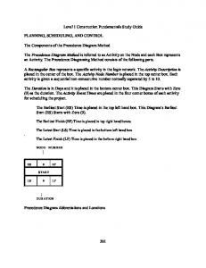


![Best Practices in Transit Service Planning - National Center for Transit ... [PDF]](https://m.moam.info/img/260x300/best-practices-in-transit-service-planning-nationa_647bc36c098a9ec8748b45f5.jpg)


