Mar 30, 2007 - Port Arthur, Tasmania, Australia. U. Czarnetzki. Institute for Plasma and Atomic Physics, CPST, Ruhr-University Bochum, Germany. R. Boswell.
PHYSICS OF PLASMAS 14, 034505 共2007兲
Plasma ionization through wave-particle interaction in a capacitively coupled radio-frequency discharge D. O’Connella兲 and T. Gansb兲 Institute for Plasma and Atomic Physics, CPST, Ruhr-University Bochum, Germany
D. Vender Port Arthur, Tasmania, Australia
U. Czarnetzki Institute for Plasma and Atomic Physics, CPST, Ruhr-University Bochum, Germany
R. Boswell SP3/RSPhysSE, ANU, Canberra, Australia
共Received 5 January 2007; accepted 27 February 2007; published online 30 March 2007兲 Phase resolved optical emission spectroscopy, with high temporal resolution, shows that wave-particle interactions play a fundamental role in sustaining capacitively coupled rf plasmas. The measurements are in excellent agreement with a simple particle-in-cell simulation. Excitation and ionization mechanisms are dominated by beam-like electrons, energized through the advancing and retreating electric fields of the rf sheath. The associated large-amplitude electron waves, driven by a form of two-stream instability, result in power dissipation through electron trapping and phase mixing. © 2007 American Institute of Physics. 关DOI: 10.1063/1.2717889兴 Although wave-particle interactions play a major role in the physics of ionized matter, the nature of this complex interaction in plasmas has predominantly been investigated theoretically and by simulations.1–6 One reason for this is that the spatio-temporal complexities of the underlying phenomena require experimental investigations using highly sophisticated diagnostics. Recent advances in optical diagnostics with high temporal resolution have made detailed investigations possible.7–9 Understanding plasma sustainment in the low pressure regime of capacitively coupled rf plasmas 共CCPs兲 is of particular importance for improving the performance and furthering the development of many technological applications, since the electron dynamics governs dissociation, excitation, and ionization processes of critical importance for surface modifications. Present understanding is largely based on theoretical investigations and modeling10–16 and power dissipation in CCPs through waveparticle interaction has been predicted in a simple particlein-cell 共PIC兲 simulation by Vender and Boswell.17 These phenomena are investigated here by combining details of the electron dynamics acquired from the PIC simulation and modern high-speed diagnostics. The experimental setup is a modified Gaseous Electronics Conference reference cell in which a planar electrode of diameter 100 mm is driven with a radio frequency of 13.56 MHz at 60 W and is supplied with hydrogen gas at a pressure of 1.2 Pa. The system is operated without a counterelectrode, resulting in a very asymmetric discharge, with a relatively large sheath at the powered electrode and a small sheath at the grounded wall. Experimental and simulation a兲
Present address: Institute for Electrical Engineering and Plasma Technology 共AEPT兲, CPST, Ruhr-University Bochum, Germany. b兲 Present address: Centre for Plasma Physics, Queen’s University Belfast, Northern Ireland, UK. 1070-664X/2007/14共3兲/034505/4/$23.00
conditions are not identical, but are very similar, and we do not expect the difference to have a substantial influence on the general effects studied here. The main experimental challenge has been the measurement of the fast dynamics of the extremely faint optical emission from the plasma under these conditions. Phase resolved optical emission spectroscopy 共PROES兲 provides non invasive access with a spatial resolution of approximately 1 mm limited in the present case to 5 mm due to binning. For the much more challenging problem of temporal resolution, we have been able to detect information on a nanosecond timescale. Balmer-alpha emission 共656 nm兲, with a relatively short lifetime of approximately 10 ns, is detected using a special fast, gate-able, intensified CCD camera 共PicoStar, LaVision兲. To select the wavelength, an electronically tunable spectral filter 共Varispec, CRI兲 is used since it combines relatively high transmission and two-dimensional spatial resolution, although here the second dimension is used to collect more photons. Light is collected from the region between the powered electrode and the grounded chamber wall with the camera synchronized to the rf generator, and measurements are performed with a 2 ns gate width. Phase resolved measurements over the entire rf cycle were obtained using a variable delay between the camera gate and the rf trigger that was varied in increments of 1 ns. For each phase measurement, the emission is integrated over several million rf cycles to obtain an adequate signal-to-noise ratio. The extremely high repetition rate of the camera accepts sequential rf cycles for integration, allowing measurements in the present conditions of very weak emission. The resulting high signal-to-noise ratio allows changes of a few percent to be distinguished, translating to a temporal resolution of the order of 1 ns for the corresponding 10 ns lifetime of H-alpha.18,19
14, 034505-1
© 2007 American Institute of Physics
Downloaded 11 Jun 2008 to 130.56.17.217. Redistribution subject to AIP license or copyright; see http://pop.aip.org/pop/copyright.jsp
034505-2
O’Connell et al.
Phys. Plasmas 14, 034505 共2007兲
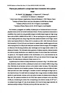
FIG. 1. Space- and phase-dependent emission measured in the experiment, over one rf cycle, close to the powered electrode, at 1.2 Pa, 60 W. Dark areas denote high excitation.
The one-dimensional PIC simulation has been described in detail elsewhere17,20 and was purposely kept as simple as possible so that fundamental mechanisms of the plasmasheath interactions could be investigated. An ion-to-electron mass ratio of 1836, corresponding to atomic hydrogen, was used and only ionizing collisions were included, with an equal share of energy between the two electrons leaving the interaction. No other collisions were considered; hence, only collisionless mechanisms can be responsible for wave damping and randomization of the electron energy distribution function. A 10 MHz sinusoidal voltage with an amplitude of 1 kV was applied to the left wall, which was 20 cm away from the earthed right wall. The comparatively large electrode gap suppresses interaction of the two sheaths in front of both electrodes. The results of an individual sheath in the simulation are, therefore, comparable to the experimental asymmetric conditions determined by one sheath. The neutral particle density in the simulation corresponds to a pressure of 1.3 Pa at room temperature. The spatio-temporal evolution of the optical emission in the vicinity of the sheath, shown in Fig. 1, is obtained by imaging a plane in the center of the discharge onto the camera where the darker regions represent higher emission intensity. The maximum extension of the sheath is about 3.5 cm and can be observed in the upper left of the figure as the large white area. In the lower left there is a region of high emission very close to the electrode followed by a powerful burst at 2.5 cm and a less intense burst at 4 cm. The second half of the rf period is characterized by the large sheath and a sequence of bright and dark regions along the sheath edge at about 3.5 cm. Very similar structures can also be observed in the phase- and space-dependent power density j · E obtained from the PIC and shown in Fig. 2. It should be noted that the
emission, in Fig. 1, reflects the dynamics of electrons with energies greater than the excitation threshold of 12.1 eV 共a small fraction of the total electrons兲, whereas the power density is derived from the motion of all electrons. In order to interpret the complicated structures evident in both figures, it is of great use to draw further information obtainable from the PIC. Figure 3 shows electron energy distribution functions at different phase and space positions, in the vicinity of the sheath edge, during the sheath contraction and expansion. Figures 2 and 3 have been published previously and are deliberately presented here to demonstrate that predictions of a PIC simulation carried out in the late
FIG. 2. Space- and phase-dependent power density, determined by E · j in the PIC simulation, close to the powered electrode. Dark areas denote power absorption by the electrons, light areas power loss.
Downloaded 11 Jun 2008 to 130.56.17.217. Redistribution subject to AIP license or copyright; see http://pop.aip.org/pop/copyright.jsp
034505-3
Plasma ionization through wave-particle interaction…
FIG. 3. Contour plot of the sheath electric field 共left兲 and electron velocity distributions in the sheath at different phase space 共right兲. The gray areas on the contour plot indicate the regions for which the distributions were summed. All distributions are normalized to the same vertical scale.
1980s17 have to await advances in diagnostic techniques for experimental verification 共or falsification!兲. The picture that emerges from these results is the following: As the sheath retreats, from phase 0 to / 3, the excess negative charge in the plasma created by the continuous loss of ions accelerated to the electrode creates a small field that accelerates electrons toward the electrode,17,21 where they eventually attain a beam velocity of about 2 ⫻ 106 m / s just in front of the electrode surface. This is equivalent to an energy of 12 eV and, taking into consideration the thermal spread of the distribution function, nearly half the electrons have an energy greater than the ionization 共and excitation兲 threshold. Consequently, the excitation observed in Fig. 1 increases significantly in this region of phase space. At the wall, there is absorption of a sufficient number of electrons to balance the total positive ion loss from the plasma over the rf period and the plasma sets up an electric field to prevent further electron loss. This field serves to reflect the electron beam back into the plasma electrons that are now advancing into the sheath region, a situation that is very unstable to an electron-electron two-stream instability at the electron plasma frequency. As the applied potential continues to decrease and the sheath is fully collapsed, the thermal electrons from the right that have drifted into the sheath region collide with the rapidly advancing sheath and are accelerated back into the plasma bulk as a second more powerful beam, also
Phys. Plasmas 14, 034505 共2007兲
reaching a velocity of about 2 ⫻ 106 m / s. As far as can be determined from the data, this is very roughly twice the sheath expansion velocity as would be expected from a hardwall collision model. This main sheath expansion phase, starting at about 2 / 3, is of particular interest. The second beam of sheathaccelerated electrons appears to interact with the already unstable local plasma and amplifies the electrostatic wave created earlier. The growth rate of these beam-generated instabilities is extremely rapid and is given by 共nb / n p兲1/3 pe, for the case of the beam density being lower than the plasma density.5 For the present experiment, the plasma frequency is about 108 Hz and the beam and plasma densities are comparable. For these conditions, the system is extremely nonlinear and not solved; however, in the absence of a better theory, the above relation can be used as an approximation. This results in a growth rate of about 109 s−1, in fairly good agreement with the PIC, which shows the wave appearing in a few nanoseconds after the beam injection. As this wave is growing at a rate significantly greater than its frequency, it attains an amplitude of a few tens of volts after only a single wave period. This is sufficient to trap the majority of the beam electrons in the wave and consequently saturate the instability. Hence, it is not possible to use quasilinear theory to derive a model, and the best strategy is to describe what is observed in the PIC and attempt to put the results into the framework of our present understanding of wave-particle interactions. In the wave frame, the electron beam slows down and is reversed at the wave potential equivalent to the beam energy.4 The trapped electrons then reverse direction and are accelerated backward in the wave frame as they slide down the wave potential. At the minimum of the wave potential they have a maximum negative velocity and in the laboratory frame can be seen to be going back to the left electrode 共Fig. 3兲. They then climb the preceding wave potential until they are once again at rest in the wave frame, reverse direction, and are accelerated in a positive direction. The process then repeats as the electrons have completed one trapped particle oscillation. Energy is being moved between the kinetic energy of the electrons and the potential energy of the wave fields. During the sheath expansion, the observed excitation, in the PROES measurement at 2.5 cm 共Fig. 1兲, decreases as the electrons are decelerated in the wave frame and momentarily move back toward the left electrode. It increases once again at 4 cm after the electrons undergo a complete trapped oscillation period and are accelerated 共to the right兲 to greater than the excitation energy. Hence, the dark areas in Fig. 1 represent the presence of electrons with energies greater than 12.1 eV 共and low wave electric fields兲, whereas Fig. 2 shows the regions of high electric field 共and consequently lower electron energies兲. Comparisons between the two figures should take this apparent “phase reversal” into account. This large-amplitude trapping appears in videos of the PIC electron velocity phase space as electron vortex rings that propagate into the plasma bulk. During this propagation,
Downloaded 11 Jun 2008 to 130.56.17.217. Redistribution subject to AIP license or copyright; see http://pop.aip.org/pop/copyright.jsp
034505-4
Phys. Plasmas 14, 034505 共2007兲
O’Connell et al.
energy is lost through inelastic collisions, as evidenced by the emission spectra. As the trapped oscillating electrons are a major perturbation of the wave, they do not perform simple harmonic motion in the wave minima but are rapidly phase mixed to produce a “heated” distribution function without a clear beam. Hence, the coherent oscillations observed in the emission and the PIC quickly die out. During the period directly following the main sheath expansion, several oscillations at a frequency related to the local plasma frequency can be observed at the sheath edge in both Figs. 1 and 2. In the PIC phase space movies there is a vortex of electrons at the sheath edge rotating at about the local plasma frequency that modulate the energetic electrons and account for the observed emission. It appears that this oscillation may be described as a series resonance of the plasma-sheath system. A simplified analytical model of the nonlinear sheath dynamics22 have been carried out yielding some insight into the basic physics of the oscillations. In conclusion, using high temporal resolution OES, wave-particle interactions are found to be an important ionization mechanism in CCPs. Combining PROES with a simple PIC simulation yields deep insight into the nonlinear plasma physics responsible for the electron dynamics. The main plasma sustaining mechanisms are revealed to be: electrons accelerated toward the wall by the retreating sheath, electrons accelerated by the expanding sheath, and electrons energized through wave-particle interactions at the sheath edge. Extremely unstable electron-electron two-stream interactions drive a large-amplitude electron wave resulting in power dissipation and electron thermalization through trapping and phase mixing of the beam electrons.
ACKNOWLEDGMENTS
The project is funded by the DFG in the frame of SFB 591 and GRK 1051. 1
I. B. Berstein, J. M. Greene, and M. D. Kruskal, Phys. Rev. 108, 546 共1957兲. 2 G. Manfredi, Phys. Rev. Lett. 79, 2815 1997. 3 M. V. Medvedev, P. H. Diamond, M. N. Rosenbluth, and V. I. Shevchenko, Phys. Rev. Lett. 81, 5824 共1998兲. 4 A. W. Degeling and R. W. Boswell, Phys. Plasmas 4, 2748 共1997兲. 5 R. J., Briggs, Electron-Stream Interaction with Plasmas 共MIT Press, Cambridge, MA, 1964兲. 6 B. Eliasson, M. E. Dieckmann, and P. K. Shukla, New J. Phys. 7, 136 共2005兲. 7 T. Gans, V. Schulz von der Gathen, and H. F. Döbele, Europhys. Lett. 66, 232 共2004兲. 8 T. Gans, V. Schulz-von der Gathen, and H. F. Döbele, Contrib. Plasma Phys. 44, 535 共2004兲. 9 T. Gans, J. Schulze, D. O’Connell, U. Czarnetzki, R. Faulkner, A. R. Ellingboe, and M. M. Turner, Appl. Phys. Lett. 89, 261502 共2006兲. 10 M. A. Lieberman, IEEE Trans. Plasma Sci. 16, 638 共1988兲. 11 M. M. Turner, Phys. Rev. Lett. 75, 1312 共1995兲. 12 M. M. Turner, Phys. Rev. Lett. 71, 1844 共1993兲. 13 G. Gozadinos, M. M. Turner, and D. Vender, Phys. Rev. Lett. 87, 135004 共2001兲. 14 I. D. Kaganovich, Phys. Rev. Lett. 82, 327 共1999兲. 15 I. D. Kaganovich, Phys. Rev. Lett. 89, 265006 共2002兲. 16 T. Mussenbrock and R. P. Brinkmann, Appl. Phys. Lett. 88, 151503 共2006兲. 17 D. Vender and R. W. Boswell, J. Vac. Sci. Technol. A 10, 1331 共1992兲. 18 T. Gans, Chun C. Lin, V. Schulz-von der Gathen, and H. F. Döbele, Phys. Rev. A 67, 012707 共2003兲. 19 T. Gans, V. Schulz-von der Gathen, and H. F. Döbele, Plasma Sources Sci. Technol. 10, 17 共2001兲. 20 R. W. Boswell and I. J. Morey, Appl. Phys. Lett. 52, 21 共1988兲. 21 U. Czarnetzki, D. Luggenhölscher, and H. F. Döbele, Plasma Sources Sci. Technol. 8, 230 共1999兲. 22 U. Czarnetzki, T. Mussenbrock, and R. P. Brinkmann, Phys. Plasmas 13, 123503 共2006兲.
Downloaded 11 Jun 2008 to 130.56.17.217. Redistribution subject to AIP license or copyright; see http://pop.aip.org/pop/copyright.jsp