Home
Search
Collections
Journals
About
Contact us
My IOPscience
Plasma particle-in-cell simulations with QED reactions for pair production experiments using a high-Z solid target
This content has been downloaded from IOPscience. Please scroll down to see the full text. 2013 J. Phys.: Conf. Ser. 454 012016 (http://iopscience.iop.org/1742-6596/454/1/012016) View the table of contents for this issue, or go to the journal homepage for more
Download details: IP Address: 54.152.109.166 This content was downloaded on 30/10/2015 at 03:33
Please note that terms and conditions apply.
24th IUPAP Conference on Computational Physics (IUPAP-CCP 2012) Journal of Physics: Conference Series 454 (2013) 012016
IOP Publishing doi:10.1088/1742-6596/454/1/012016
Plasma particle-in-cell simulations with QED reactions for pair production experiments using a high-Z solid target Toseo Moritaka1 , Luca Baiotti1,2 , An Lin1,2 , Li Weiwu1,2 , Youichi Sakawa1,2 , Yasuhiro Kuramitsu1 , Taichi Morita1 and Hideaki Takabe1,2 1 2
Institute of Laser Engineering, Osaka University, 2-6 Yamadaoka, Suita, Osaka, Japan Graduate School of Science, Osaka University, Machikaneyama, Toyonaka, Osaka, Japan
E-mail:
[email protected] Abstract. A new simulation scheme has been developed to investigate high-energy plasma phenomena including pair production and Bremsstrahlung in a high-Z nuclear field. The simulation scheme consists of (1) a Particle-in-Cell scheme for relativistic plasma dynamics, (2) a conservative semi-Lagrangian scheme for hard photon transport and (3) a Monte-Carlo scheme for the considered QED reactions. The developed scheme is applied to a test simulation relevant to recent experiments of positron production from a thin gold target irradiated by a high intensity laser. The simulation results successfully show a basic process leading to the positron ejection from the target. The process involves electron acceleration due to laser-plasma interaction at the target front, hard photon emission and pair production inside the target, and electrostatic positron acceleration at the target rear side.
1. Introduction Recent progress in high-intensity laser technology is making possible a new experimental approach to high-energy plasma dynamics coupled with quantum electrodynamics (QED) processes. Such plasma dynamics play an important role in high-energy astronomical phenomena in neutron star magnetospheres [1], accretion discs around black holes [2] and so on. Theoretical estimates indicate that laser-plasma interaction under the dominant influence of QED effects can be obtained by using high-intensity lasers with I ∼ 1024−25 W/cm2 [3,4], which will be realized at facilities currently under project [5]. In this interaction regime, active pair production would take place mediated by hard photon emission from accelerated electrons in the strong laser field [6-13]. Pair production could be attained also with the available laser intensities of I ∼ 20−21 10 W/cm2 by using a high-Z solid target. In this case, the strong nuclear field of high-Z ions enhances hard photon emission and subsequently pair production [14,15]. Such experiments have already been performed; for example energy spectrum measurements have been carried out for positrons ejected from a thin gold target irradiated by a high intensity laser [16-18]. The experimental results are, however, not fully described by current numerical simulations because traditional simulation methods, such as plasma particle-in-cell (PIC) [19] and Monte-Carlo Content from this work may be used under the terms of the Creative Commons Attribution 3.0 licence. Any further distribution of this work must maintain attribution to the author(s) and the title of the work, journal citation and DOI. Published under licence by IOP Publishing Ltd 1
24th IUPAP Conference on Computational Physics (IUPAP-CCP 2012) Journal of Physics: Conference Series 454 (2013) 012016
IOP Publishing doi:10.1088/1742-6596/454/1/012016
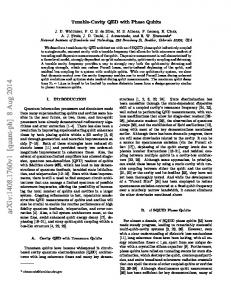
particle transport methods [20], can address only one side of the laser-target interaction, i.e., either the collective plasma dynamics or the quantum stochastic process of positron production. In order to approach a full numerical description of pair production processes in high-Z targets, we have developed a new simulation scheme that includes both QED processes and plasma dynamics. The simulation scheme is based on the PIC model commonly used to study kinetic phenomena in laser-plasma interaction. Additional computation procedures are integrated into the PIC simulation scheme to evaluate the time evolution of hard-photons and stochastic QED reactions. The considered QED reactions, Bremsstrahlung and pair production [14,21,22], are characterized by two features: a rather weak transition rate (typically λ ∼ (10 - 100) × L) and an enormous number of potential seed particles (typically N ∼ 1021 [1/cm3 ]), where λ, L and N denote interaction mean free path, system size and plasma number density, respectively. These features are relevant to the experimental result that the detected number of positrons is statistically considerable but much less than that of electrons [16,18]. In order to capture the products of Bremsstrahlung, we employ a fluid description for hard photons in multi-dimensional phase space. Since one PIC super-particle contains a lot of real particles, the super-particle emits a certain number of hard photons in one time step interval. Electron super-particles lose a part of their momentum every time step, and corresponding fractions of photon momentum are distributed into the discrete photon momentum space. In this way, low photon density can be captured as a continuous quantity. Pair production is also regarded as a continuous process that takes place every few time steps. Generated electron-positron pairs are given by test particles with continuous small weights estimated from the cross section of pair production and the photon momentum distribution. Another difficulty arises from the treatment of the nuclear field producing the QED reactions. PIC simulations cannot resolve the nuclear field explicitly because its spatial scale is much smaller than the Debye length characterizing the grid separation. The Bremsstrahlung process is described as momentum and energy exchange processes among randomly selected electronion pairs and emitted photons, and is evaluated by an extension of the Monte-Carlo binary collision model [23]. Photon momentum and emission angle are computed from random numbers distributed according to the cross sections for relative momenta of each particle pair. As a test, the scheme is applied to high-intensity laser interaction with a thin solid target. Simulation results successfully show a series of plasma and QED processes leading to positron ejection from the target. Seed particles for the QED reaction are high-energy electrons accelerated by the pulse laser in the low-density pre-plasma region at the target front. These electrons penetrate into the target with higher density and result in pair production mediated by hard-photon emission. It is also confirmed that positron acceleration due to the electrostatic field at the target’s rear side dominantly characterizes the positron energy distribution. This paper is organized as follows. In section 2, we introduce the details of the simulation scheme. Results of the test simulation are shown in section 3. Finally, the present study is summarized in section 4. 2. Numerical Scheme The numerical scheme is based on a plasma PIC model [19]. PIC simulations describe collective plasma dynamics and have been employed widely for numerical studies on kinetic plasma phenomena in space and laboratories. We integrate two additional procedures relevant to pair production into the PIC simulation model. One evaluates the time evolution of the hard photons that mediate pair production. The other estimates stochastic QED reactions by Monte-Carlo calculation using random numbers. Figure 1 shows the global picture of the simulation scheme. Physical objects considered in the simulation are classified into two categories - photons and particles (left part of figure 1).
2
24th IUPAP Conference on Computational Physics (IUPAP-CCP 2012) Journal of Physics: Conference Series 454 (2013) 012016
IOP Publishing doi:10.1088/1742-6596/454/1/012016
Figure 1. Schematic diagram of the simulation scheme. Physical objects considered in the simulation are surrounded with a color solid line. Arrowed lines represent the connections among these objects. Boxes surrounded by color dashed lines refer to processes computed with a given numerical schemes. “Photons” include the electromagnetic field and hard photons (top boxes in figure 1). Their time evolutions are computed separately by different numerical schemes. In the present simulation, electron-positron pairs produced during the evolution are treated separately from the initial electron-ion plasma (bottom boxes in figure 1). Details of the numerical treatment for these physical objects are explained in the following subsections. 2.1. Time evolution of electromagnetic field and plasma Time evolutions of the plasma and the electromagnetic field are determined by Newton-Lorentz and Maxwell equations in the framework of the PIC simulation (left side of figure 1). The electromagnetic field is discretized on a uniform spatial grid and the Maxwell equations are solved by a leapfrog finite difference method. The plasma dynamics are given by the motions of super-particles with a finite volume comparable to the Debye shell. One super-particle represents a macroscopic number of real particles. This treatment enables us to examine various kinetic properties of the plasma by using a reasonable number of computational particles. At each time step, the displacements of super-particles are combined to estimate the current density term in the Maxwell equations. The calculation cycle is closed through the computation of the Lorentz force and current density, as shown in the left side of figure 1. 2.2. Time evolution of hard photons Time evolution of hard photons is computed to examine the pair production process that is mediated by hard photons. The energy of a hard photon should exceed twice the electron rest mass energy. The corresponding frequency is much higher than the plasma frequency in our case. Therefore hard photons can be clearly separated from the electromagnetic field evaluated in the PIC simulation. Photons with intermediate frequency contribute to neither plasma dynamics nor pair production and are ignored in the present simulation. The spatial grid employed in the PIC simulation cannot resolve the hard photons because 3
24th IUPAP Conference on Computational Physics (IUPAP-CCP 2012) Journal of Physics: Conference Series 454 (2013) 012016
IOP Publishing doi:10.1088/1742-6596/454/1/012016
their wavelength is much smaller than the grid size. Instead, we employ a multi-dimensional phase space for hard photons. Hard photons with different momenta are distinguished by their position in the additional momentum space. In phase space, time evolution of hard photons is governed by the photon transport equation, ∂f (r, p) =n ˆ · (∇f (r, p)) = δf (r, p), c∂t
(1)
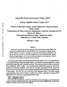
where c, n ˆ and f (r, p) denote light speed, propagation direction and photon distribution in phase space (r, p). Here, left-hand side terms indicate photon advection and the right-hand side term gives the photon absorption associated with photon-matter interaction. A conservative Constrained Interpolation Profile scheme (CIP-CSL2) is employed to simulate photon advection. The CIP scheme is a semi-Lagrangian method and has been widely used in fluid simulations [24]. The total number of fluid elements is exactly conserved in this scheme. Photon advection in real space is calculated individually with computational cells in momentum space. Accordingly, total momentum and energy are conserved in the photon advection process. The photon-matter interaction depends on the photon energy and the kind of material. For gold, the dominant interactions of hard photons are pair production (≥ 5MeV) and Compton scattering (≤ 5MeV) [22]. Total cross sections of these interactions have relatively weak dependency on photon energy, which is roughly characterized by the logarithm of photon energy. Therefore non-uniform logarithmic coordinates would be effective to represent photon momentum space within a limited computational memory. Figure 2 shows the cylindrical coordinate used for photon momentum space. Logarithmic coordinates are employed for radial distance in the x-y plane Pxy and for the distance in the z-direction Pz . 2.3. Treatment of QED reactions The dominant QED reaction leading to pair production is the interaction between hard photons and the high-Z nuclear field [17,22]. Bremsstrahlung from electrons accelerating in the high-Z nuclear field mainly contributes the hard photon emission [14,21]. Therefore these two QED reactions are considered in the present simulation. Their positions in the whole simulation procedure can be seen in the right side of figure 1. The spatial grid used in the PIC simulation does not resolve Bremsstrahlung processes, which have characteristic scale of atomic size. Thus, we employ a coarse-graining approach statistically
Figure 2. Cylindrical coordinates for photon momentum space. The photon momentum is given by three independent parameters, the angle θ and the absolute value of Pxy in the x − y plane and the z−component Pz . Logarithmic coordinates are employed for Pxy and Pz . 4
24th IUPAP Conference on Computational Physics (IUPAP-CCP 2012) Journal of Physics: Conference Series 454 (2013) 012016
IOP Publishing doi:10.1088/1742-6596/454/1/012016
Figure 3. Numerical procedures for Bremsstrahlung. Red and blue boxes indicate ion and electron super-particles, respectively. Yellow circles indicate temporary photons with individual momenta. These photons are distributed into the photon momentum space in the last procedure (E). consistent with theoretical cross sections. This approach is similar to the Monte-Carlo binary collision model with particle pairing [23]. In this model, binary collisions are described as a momentum exchange process between a pair of super-particles selected within a common spatial grid. This approach is extended to the momentum exchange among electrons, ions and photons consistently with Bremsstrahlung cross sections. Numerical procedures associated with the Bremsstrahlung are summarized in figure 3. The following items A)∼ E) relate to the panels (A)∼(E) in the figure. A) An electron-ion pair is randomly selected from super-particles (gray boxes) that belong to a common spatial grid. The red and blue boxes indicate the selected electron-ion pair. The symbols Pele and Pion denote the electron and ion momenta, respectively. B) A Lorentz transformation is applied to move into the center-of-mass (COM) frame of the electron-ion pair. The electron and ion have symmetric momenta Prel and −Prel in the COM frame. C) Bremsstrahlung photons (yellow circles) are considered. The Bremsstrahlung cross sections are estimated from the relative momentum by using a prepared data table. Electron energy ′ gives the resulting electron momentum. loss is determined by the total cross section. Prel The photon momenta Pphoton and emission angles θ are computed from random numbers statistically distributed according to the differential cross sections, and the photon number is determined so as to satisfy the energy conservation. The angle components are chosen axisymmetrically with respect to the direction of relative momentum.
5
24th IUPAP Conference on Computational Physics (IUPAP-CCP 2012) Journal of Physics: Conference Series 454 (2013) 012016
IOP Publishing doi:10.1088/1742-6596/454/1/012016
D) Total photon momentum is directed parallel to the electron-ion relative momentum. However, its absolute value is not consistent with the electron momentum loss. This inconsistency is resolved by re-distributing the momentum from electron to ion. The ′ → P ele and −P ion electron and ion momenta are corrected as Prel rel → Prel , respectively. rel E) The Lorentz transform is applied inversely. Electron, ion and photon momenta are updated ′ , P′ ′ in the laboratory frame (Pele ion and Pphoton , respectively). Finally, the photon momenta are distributed to the nearest cells in the momentum space as shown in the right panel. The procedures described above are repeated for each spatial grid until all electron (or ion) super particles are once processed. Next, we explain the numerical procedures for pair production. The reduction rate of photons is determined by the total cross section of pair production based on the photon energy. In principle, the computation of pair production should happen in each cell in momentum space according to the individual photon cross section. However, this approach requires a large number of computational particles if pair production is processed every few time steps. In order to avoid this problem, we define a few representative photons for each spatial grid consistently with the expected cross section in momentum space. Pair production is estimated for these representative photons and randomly selected ions. This approach limits the increase of computational particles.
Figure 4. Numerical procedures for pair production. Top panels represent statistical treatments for photon distribution in momentum space. Yellow circles indicate representative photons with individual momentum and the number of contained photons. Bottom panels represent the interaction of each representative photon with a randomly selected ion. Blue and red boxes represent an ion super-particle and an electron-positron pair. Initially, electron and positron are placed at the same position.
6
24th IUPAP Conference on Computational Physics (IUPAP-CCP 2012) Journal of Physics: Conference Series 454 (2013) 012016
IOP Publishing doi:10.1088/1742-6596/454/1/012016
Numerical procedures associated with pair production are summarized in figure 4. The following items A) ∼ F) relate to the panels (A)∼(F) in the figure. A) The momentum-space distribution of the photons contributing pair production, δn(p), is estimated for each cell in momentum space according to the total cross section. The histogram in the figure indicates the profile of photon number in momentum space. Photon momentum distribution is updated with the remaining photon number n′ (p) = n(p)−δn(p), where n(p) denotes initial photon distribution. B) Linearly interpolated cumulative distribution functions (red line with dots) are computed from δn(p) for two momentum spaces, region 1 and region 2. Here, the momentum space is divided at the average momentum in δn(p), namely pave . The momenta of the two representative photons, p1 (< pave ) and p2 (> pave ), are defined from random numbers, r1 and r2 , by using the cumulative distribution functions. P C) Total number of photon reduction (N = p δn(p)) is distributed into these representative photons, N1 and N2 (N = N1 + N2 ), so that the total reduction of photon momentum is equal to the representative photon momentum (N pave = N1 p1 + N2 p2 ). In the figure, the yellow circles indicate the representative photons. Positive solutions N1 , N2 can be obtained if p1 < pave < p2 is fulfilled. D) We consider the interaction between the representative photon and ion. The ion (blue box) is randomly selected from the ion super-particles belonging to the same spatial grid (orange square). E) In the ion rest frame, the momenta of the generated particle pair, pele and ppos , are computed according to the photon momentum p′photon and the cross section of pair production. The number of particle pairs is equal to the photon number contained in the representative photon. The inconsistency between photon momentum and total momentum of the particle pair is resolved by re-distributing the momenta between ion and particle pair. At the end, the ion has a finite momentum ∆pion in this frame. F) Finally, a Lorentz transform into the laboratory frame is applied. One obtains electron, positron and ion momenta (p′ele , p′pos and p′ion ) consistent with the photon reduction. The generated particle pair is described as two test particles with continuous weights. The particle weight represents the number of contained real particles. The test particles move according to the Lorentz force but do not contribute current density and recursive pair production (see the bottom right part of figure 1). This treatment is valid for the present situation because the number density of particle pairs is negligibly small compared to that of the initial plasma. Numerical cost due to the increment of particle pairs is reduced dramatically by this treatment. Additionally, Bremsstrahlung procedures would become more complicated without this treatment because random pairing cannot be applied directly for super-particles with different weights. 3. Test simulation 3.1. Simulation model The developed simulation scheme is applied to a test simulation of positron production in a solid gold target. Figure 5 shows the initial setup of the simulation. A two-dimensional simulation domain is considered with an initial laser pulse and a high-density target. The initial laser pulse is placed at the left side of the simulation domain and propagates rightward (+x direction). A lowdensity plasma region (pre-plasma region) is located at the target front [10.5 µm < x < 19.5 µm p < ω < ω t , where in figure 5(A)]. The laser frequency ωL is set so as to fulfill the condition ωpe L pe p and ω t are the plasma frequencies at the pre-plasma and the target, respectively. Under ωpe pe this condition, the laser pulse basically penetrates into the pre-plasma but is reflected in the 7
24th IUPAP Conference on Computational Physics (IUPAP-CCP 2012) Journal of Physics: Conference Series 454 (2013) 012016
IOP Publishing doi:10.1088/1742-6596/454/1/012016
Figure 5. Initial condition for the test simulation. (A) Spatial profile of initial ion density normalized to the critical density Ncr . The initial density profile of electrons is the same as that of ions. (B) Spatial profile of initial electric field Ey normalized by the unit electric field E(20) that corresponds to the focusing intensity 1020 W/cm2 . target. In the experiment, the pre-plasma is generated because of the ionization of the solid target by the preceding pulse of the high intensity laser. A similar model has been employed for some numerical studies on ion acceleration using high-intensity laser and solid target by means of traditional PIC simulations [25]. The principal simulation parameters are set as follows. The simulation domain is implemented on a (1536 × 1024) grid. Initial number of super-particle per spatial grid is 67 at the preplasma and 480 at the target for each particle species. Physical parameters are estimated for reference plasma density 1021 cm−3 at the pre-plasma. Laser intensity corresponding to the initial pulse laser is 7 × 10²⁰ W/cm2 . Pulse and spot sizes are 4.9µm and 3.1µm, respectively. Lengths of pre-plasma and target regions are 9.0µm and 3.9µm, respectively. Target density is 7.2 × 1021 cm−3 , while the critical density for the initial laser pulse is estimated to be Ncr = 1.7 × 1021 cm−3 . Radiation and periodic boundary conditions are employed for the x− and y−directions, respectively. 3.2. Simulation results Figures 6(A) and (B) show the electric field and electron density profiles at the early phase (ct = 12.8 µm) when the laser pulse penetrates into the under-dense pre-plasma region [see figure 6(A)]. Vertical lines in the figures indicate the initial locations of the pre-plasma region and the target. The laser pulse pulls out the plasma from the laser transit region by exerting ponderomotive force [26]. In consequence, a wake structure is formed in the pre-plasma region as shown in figure 6(B). Figures 6(C) and (D) show the phase-space plots for electron momenta in the x- and ydirections, respectively. One can see the electron acceleration in the +x-direction as well as the oscillation in the ±y-directions. The momentum of some electrons reaches up to px ∼ 100me c. The high-energy electron component comes from resonance acceleration in the oscillating plasma wake structure, while the electron motion in the ±y-direction originates from a direct response to the laser fields. The basic acceleration mechanism in such non-linear laser-plasma interaction is referred to as ”plasma wake-field acceleration” [27]. Figure 7(A) shows the electron phase-space plot at a later phase (ct = 20.3 µm) after the laser pulse reaches the target surface. The accelerated electrons pass through the high-density target region in contrast to the laser field that dissipates in the target. These electrons play a critical 8
24th IUPAP Conference on Computational Physics (IUPAP-CCP 2012) Journal of Physics: Conference Series 454 (2013) 012016
IOP Publishing doi:10.1088/1742-6596/454/1/012016
Figure 6. Laser-plasma interaction in the pre-plasma region at ct = 12.8 µm. (A) Spatial profile of the electric field Ey normalized to the unit electric field E(20). (B) Spatial profile of the electron density Ne normalized to the critical density Ncr . (C) Phase-space plot for electron momentum in the x-direction Px . (D) Phase-space plot for electron momentum in the y-direction Py . Vertical lines indicate the initial locations of the pre-plasma region and the target.
Figure 7. Photon emission from accelerated electrons inside the target at ct = 20.3 µm. (A) Phase-space plot for electron momentum in x-direction, Px . (B) Spatial profile of photon number Nh . Hard photons with energy Ep > 2me c2 are counted here and the photon number is normalized to 10−3 Ncr . Vertical lines indicate the initial locations of the pre-plasma region and the target. 9
24th IUPAP Conference on Computational Physics (IUPAP-CCP 2012) Journal of Physics: Conference Series 454 (2013) 012016
IOP Publishing doi:10.1088/1742-6596/454/1/012016
Figure 8. Positron generation and acceleration at ct = 25.4 µm. (A) Spatial profile of positron density, Np , normalized to 10−5 Ncr . (B) Phase-space plot for positron momentum in the xdirection, Px . Vertical lines indicate the initial locations of pre-plasma region and target. role as seed particles in subsequent photon emission and pair production because Bremsstrahlung is enhanced for higher electron energy and higher density of high-Z nuclei. Figure 7(B) shows the spatial profile of a hard photon with energy larger than 2me c2 . Hard photons are found dominantly at the vicinity of the accelerated electrons passing through the target. Figure 8(A) shows the positron density profile normalized to 10−5 Ncr at ct = 25.4 µm. Positrons are generated as hard photons propagate inside the target. As a result, the positron distribution follows the arch distribution of spreading hard photons. Figure 8(B) shows the phase-space plot for positron momentum in the x-direction, px . The distribution is sampled from the positron test particles in the central region of the simulation domain, 12.2 µm < y < 13.8 µm. Inside the target, positron momentum stays at a lower level compared to that of the seed electrons accelerated in the pre-plasma. This is because the differential cross section of Bremsstrahlung is strongly biased toward low-energy photon emission. By contrast, positrons with considerable momentum are found behind the target (x > 23 µm). These positrons are accelerated originally by the sheath electric field induced at the rear side surface of the target. Induction of the sheath electric field comes from the violation of charge neutrality of the target due to electron penetration from pre-plasma. The resulting negative charge propagates through the free electrons in the target, and finally an electrostatic field is induced at the rear side in the direction perpendicular to the target surface (+x direction). While electrons tend to be confined inside the target under the influence of this electrostatic field, positrons with positive charge tend to accelerate in the rearward direction. The acceleration mechanism due to sheath electric field has been referred to as the origin of effective ion acceleration in the laser-solid interaction. The simulation results indicate that the positron energy spectrum is dominantly determined by the acceleration in the sheath electric field. This mechanism might elucidate the discrepancy of positron energy spectrum between Monte-Carlo simulation and experimental results [16,18]. 4. Conclusion Recent progress in high intensity lasers is allowing the experimental investigation of highenergy plasma phenomena under the influence of quantum electrodynamics (QED) effects. One available example is the positron measurement carried out on a thin gold target with a highintensity laser [16-18]. Aiming at the numerical investigation of such experiments, we have
10
24th IUPAP Conference on Computational Physics (IUPAP-CCP 2012) Journal of Physics: Conference Series 454 (2013) 012016
IOP Publishing doi:10.1088/1742-6596/454/1/012016
developed a new simulation scheme including both collective plasma dynamics and stochastic QED reactions. The developed scheme is based on the plasma particle-in-cell (PIC) method. Additional procedures associated with QED reactions are integrated into the PIC framework. Considered QED reactions are Bremsstrahlung and pair production in a high-Z nuclear field. Under experimental conditions, these reactions are characterized by an extremely low transition rate and a macroscopic number of seed particles. A fluid description of hard photons is employed in a multi-dimensional phase space to capture the small fraction of photon emission as a continuous quantity. Additional procedures include a conservative Constrained Interpolation Profile (CIP) scheme for hard-photon transport and Monte-Carlo schemes for QED reactions. The QED reactions are described as momentum and energy exchange processes between plasma (superparticles), hard photons (fluid) and particle pairs (test particles with continuous weights). The Monte-Carlo schemes are designed so as to satisfy conservation laws and statistical consistency with theoretical cross sections. A test simulation of positron production in a thin solid target is performed by means of the developed simulation scheme. The simulation results successfully show that a series of basic physical processes leads to positron ejection from the target. Considered physical processes involve electron acceleration due to laser-plasma interaction in the pre-plasma region, pair production mediated by hard photon emission inside the target and positron acceleration due to sheath electric field at the target rear side. The developed simulation scheme is a promising computational approach for full-scale simulation studies of pair production experiments using high-Z targets. Key themes for future work would be, for example, quantitative understanding of the controlling mechanism of the positron energy spectrum and ejection angle distribution and of the dependency of laserto-positron energy conversion rate on experimental setup, and experimental optimization for effective positron production. Acknowledgments The authors acknowledge Professor A Titov (Joint Institute for Nuclear Research, Russia) and Professor H Ruhl (Universit¨at M¨ unchen, Germany) for useful discussions. The calculations were performed on the ILE computer system at the Institute of Laser Engineering in Osaka University and on the Plasma Simulator at the National Institute for Fusion Science. Part of the simulation code is developed by using the K computer at the RIKEN Advanced Institute for Computational Science (Proposal number hp120267). This work was partially supported by the General Coordinated Research at National Institute for Fusion Science (NIFS13KNSS039). References [1] Timokhin A N 2010 Monthly Notices of the Royal Astronomical Society 408 2092 [2] Ruffini R, Vereshchagin G and Xue S 2010 Physics Reports 487 1 [3] Bulanov S V et al 2011 Nuclear Instruments and Methods in Physics Research A 660 31 [4] Sokolov I V, Naumova N M and Nees J A 2001 Phys. Plasmas 18 093109 [5] THE EXTREME LIGHT INFRASTRUCTURE (http://www.extreme-light-infrastructure.eu/) [6] Bell A R and Kirk J G 2008 Phys. Rev. Lett. 101 200403 [7] Kirk J G, Bell A R and Akra I 2009 Plasma Phys. Controlled Fusion 51 085008 [8] Nerush E N, Kostyukov I Yu, Fedotov A M, Narozhny N B, Elkina N V and Ruhl H 2011 Phys. Rev. Lett 106 035001 [9] Elkina N V, Fedotov A M, Kostyukov I Yu, Legkov M V, Narozhny N B, Nerush E N and Ruhl H 2011 Physical Review Special Topics - Accelerator and Beams 14 054401 [10] Ridgers C P, Brady C S, Duclous R, Kirk J G, Bennett K, Arber T D, Robinson A P L and Bell A R 2012 Phys. Rev. Lett 108 165006 11
24th IUPAP Conference on Computational Physics (IUPAP-CCP 2012) Journal of Physics: Conference Series 454 (2013) 012016
IOP Publishing doi:10.1088/1742-6596/454/1/012016
[11] Erber T 1966 Reviews of Modern Physics 15 626 [12] Ritus V I 1985 Journal of Soviet Laser Research 6 497 [13] Titov A I, Takabe H, Kampfer B and Hosaka A 2012 Phys. Rev. Lett 108 240406 [14] Heitler W 1954 The Quantum Theory of Radiation (The Oxfort University Press) [15] Koch H W and Motz J W 1959 Reviews of Modern Physics 31 920 [16] Cowan T E et al 1999 Laser and Particle Beams 17 773 [17] Nakashima K and Takabe H 2002 Phys. Plasmas 9 1505 [18] Chen H et al 2011 High Energy Density Physics 7 225 [19] Birdsall C K and Langdon A 1991 Plasma Physics via Computer Simulation (Adam Hilger) [20] For example, The Electron Gamma Shower (EGS) (http://rcwww.kek.jp/research/egs/) [21] ESTAR: Stopping-Power and Range Tables (http://www.nist.gov/pml/data/star/index.cfm) [22] XCOM: Photon Cross Section Database (http://www.nist.gov/pml/data/xcom/index.cfm) [23] Sentoku Y, Mima K, Kishimoto Y and Honda M 1998 Journal of the Physical Society of Japan 67 4084 [24] Yabe T, Tanaka R, Nakamura T and Xiao F 2001 Mon. Wea. Rev. 129 332 [25] Fourkal E, Shahine B, Ding M, Li J S, Tajima T and Ma C.-M 2002 Medical Physics 29 2788 [26] Landau L D and Lifshitz E M 1975 The Classical Theory of Fields, 4th ed., (Pergamon Press, Oxford, New York) [27] Tajima T and Dawson J 1979 Phys. Rev. Lett. 43 267
12