passive structures of ITER vessel introduce a not negligible delay on the control .... mentioned variables represent variations with respect to their equilibrium ...
Proceedings of the 47th IEEE Conference on Decision and Control Cancun, Mexico, Dec. 9-11, 2008
WeB18.4
Plasma position and shape control in ITER using in-vessel coils G. Ambrosino† , M. Ariola‡ , G. De Tommasi† , A. Pironti† , A. Portone§
Abstract— The International Thermonuclear Experimental Reactor (ITER) is the next step toward the realization of electricity-producing fusion power plants. ITER has been designed so as to reach the plasma burning condition, and to operate with high elongated unstable plasmas. However, due to the constraints which affect the machine realization, these open-loop unstable high performance plasmas can be hardly stabilized using the Poloidal Field (PF) coils placed outside the tokamak vessel. For this reason, during the ITER design review phase, it has been proposed to investigate the possibility of using in-vessel coils, in order to improve the best achievable performance of the vertical stabilization system. Because of some technological differences between the in-vessel coils and the PF coils (the former cannot be superconductive), the controller design procedure previously adopted in [1] cannot longer be used. This paper proposes a new approach for the plasma current, position, and shape control design in the presence of in-vessel coils. In particular two control loops are designed: a first loop which guarantees the vertical stabilization by means of a MISO controller which drives the voltage applied to in-vessel coils; a second MIMO loop controls the plasma current and up to 32 geometrical shape descriptors as close as possible to the reference values.
8 PF1 6
PF2 CS3U
4 CS2U PF3
2 CS1U
Plasma Boundary
0 CS1L
PF4
CS2L −4
Passive structures CS3L
−6 PF5
−8
The need of achieving always better performance in present and future tokamak devices, has pushed plasma control to gain more and more importance in tokamak engineering (see the special issues [2] and [3]). Since the elongated plasmas required to achieve high performance are vertically unstable, position control is clearly an essential feature of all machines. Beyond this, a strong motivation to improve plasma control is that, in order to obtain best performances out of a device, it is always necessary to maximize the plasma volume within the available space; hence, the ability to control the shape of the plasma (e.g. by changing its elongation, triangularity etc.) while ensuring good clearance between plasma and the facing components (e.g. first wall) is an essential feature of any Poloidal Field (PF) control system (see Fig. 1). The International Thermonuclear Experimental Reactor (ITER) is the next step toward the realization of electricityproducing fusion power plants. The main goal of the ITER tokamak [4] is to attain plasma burning condition (see Tutorial 2 in [2]), and produce about 500 MW of fusion generate-power for more than 400 s [5]. To estimate the † G. Ambrosino, G. De Tommasi and A. Pironti are with the Associazione Euratom-ENEA-CREATE, Dipartimento di Informatica e Sistemistica, Universit`a di Napoli, Via Claudio 21, 80125, Napoli, Italy. ‡ M. Ariola is with the Associazione Euratom-ENEA-CREATE, Dipartimento per le Tecnologie, Universit`a degli Studi di Napoli Parthenope, via Medina 40, 80133 Napoli, Italy. § A. Portone is with the EFDA-CSU, Josep Pla 2, B3, Barcelona, Spain.
In−vessel coils
−2
I. I NTRODUCTION
978-1-4244-3124-3/08/$25.00 ©2008 IEEE
First wall
PF6 0
2
4
6
8
10
12
Fig. 1. ITER cross-section and Poloidal Field (PF) coils system. Note that the Central Solenoid (CS) coils are part of the PF system.
effort required to build ITER, it may help noting that its major radius is twice the one of the Joint European Torus (JET) [6], which is the today’s world largest fusion reactor. Furthermore the plasma current in ITER will be of about 15 MA, which is more than twice the maximum current obtained during JET operation in the last 20 years. Although high performance are needed to reach the desired objectives, the design of the ITER plasma position and shape control system is affected by a number of constraints which are strongly related to the effective realization of the facility. In particular while elongated and vertical unstable plasmas, with β p up to 1.9, and li up to 1.2, are envisaged so as to guarantee the needed particle and energy confinement1 , the power available to control such plasmas is limited, thus saturation levels of the actuators are present. Moreover the passive structures of ITER vessel introduce a not negligible delay on the control action, when the PF coils are used to perform the plasma vertical stabilization. Recently, during the design review phase, it turned out that 1 β and l measures the plasma internal distributions of pressure and p i current respectively, and they can be regarded as disturbances as far as the plasma shape and position control is concerned.
3139
47th IEEE CDC, Cancun, Mexico, Dec. 9-11, 2008
WeB18.4
the high elongated and unstable plasmas needed for ITER operations can be hardly stabilized using the superconducting PF coils placed outside the tokamak vessel. For this reason it has been proposed to investigate the possibility of using invessel coils (see Fig. 1), so as to improve the best achievable performance of the vertical stabilization system. The problem of designing a plasma current, position and shape controller using in-vessel coils is tackled in this paper. It is worth noticing that in-vessel coils, which cannot be superconductive, do not permit to use a simple derivative action on the plasma vertical position to stabilize the plasma. It follows that a further control action must be added so as to vertically stabilize the plasma. Although a possible solution is obtained adding a proportional action on the plasma position, such an approach would determine a strong interaction between the vertical stabilization system and the shape controller, which controls the plasma shape and position. In order to avoid such an interaction, in the proposed approach we replace the proportional action on the vertical position with a proportional action on the current flowing in the in-vessel coils. In particular two control loops are designed: • •
the vertical stabilization system, which stabilizes the plasma vertical position; the plasma current and shape control system, which drives the plasma current error to zero, and minimizes the error between the actual plasma boundary and the desired shape reference.
As far as the plasma shape control is concerned, the proposed approach combines the solutions previously presented by some of the authors in [1] and [7], allowing us to control extremely shaped plasmas. It is worth noticing that the proposed vertical stabilization system consists of first order MISO controller, whose output is the voltage applied to the in-vessel coils. The simple structure of the proposed controller permits to envisage effective adaptive algorithms, and to mitigate the effect of the measurement noise on the control performance. Eventually closed-loop simulation are carried out using the CREATE-L model [8] for the ITER plant, so to illustrate the performance of the proposed control system. II. T HE PLANT MODEL A tokamak device is a rather complex system, including the plasma, the active coils, and the metallic structures (hereafter named passive conductors). What we are mainly interested in are the electromagnetic interaction of the plasma with the surrounding coils and the control of the plasma current, position, and shape. For these purposes it is possible to approximate the plasma behavior using a simplified model. In particular linearizing around an equilibrium configuration, it is possible to obtain the following set of equations [9]2 2 The linear model (1) is attained under the assumption of non-resistive plasma.
∗ L12 ∗ L22 ∗ L32
∗ L11 L∗ 21 ∗ L31 0 + 0 0
zp =
¡
y=
0 R22 0
cT1z ¡
C1
cT2z
C2
∗ L13 ∗ L23 ∗ L33 0 0 R33
x˙ p f x˙ic x˙ec xp f I xic = 0 0 xec
xp f cT3z xic , xec xp f ¢ C3 xic , xec ¢
, ¶ µ 0 u pf I uic 0 (1a) (1b)
(1c)
where: ¡ ¢ T xT T is the state space vector, which • x = xTp f xic ec includes the currents in the PF coil used for plasma shape control x p f , the currents in the in-vessel coils xic used for plasma vertical stabilization, and the passive currents xec (eddy currents), reduced to a number of short cut circuits with the aid of a finite element approximation; ¡ ¢T is the input voltage vector, which in• u = uTp f uT ic cludes the voltages applied to the PF coils u p f , and the voltages applied to the in-vessel coils uic ; • z p is the plasma vertical position; ¡ ¢T • the y = gT I p vector includes the plasma shape geometrical descriptors g and the plasma current I p . To control the plasma shape with the needed accuracy, the boundary is usually described by plasma-wall distances, which are called gaps, and by the locations of the strikepoints on the divertor tiles (see Fig. 2). Remark 1: As usual in a linearized model, all the above mentioned variables represent variations with respect to their equilibrium values. ♦ ∗ The elements of the matrices L and R in (1) have the formal role of inductances and resistances in circuits where the currents – x p f , xic , and xec – are driven by the external voltages, which are those applied to the active control coils.The upper-left hand entry of the R matrix reflects the fact that the PF coils are superconductive. The plasma model (1) has to be completed with the models of the power supply and of the diagnostic systems. As far as the power supply system is concerned, its inputs are the voltages demanded by the feedback controller and its outputs are the actual voltages applied to both the PF and the invessel coils. For our purposes it is enough to approximate the power supply system as a saturation plus a pure time delay τ1 , and a first order dynamic characterized by a pole at 1/τ2 . Two types of converters are used: the Main Converters (MC) for the PF coils, i.e. PF1-6, CS1U, CS1L, CS2U, CS2L, CS3U and CS3L (note that the CS1U and the CS1L coils are connected in series), and a fast converter, linked to the in-vessel coil, for the vertical stabilization (VS). Table I gives the time parameters τ1 and τ2 together with the saturation voltages umax for each converter.
3140
47th IEEE CDC, Cancun, Mexico, Dec. 9-11, 2008
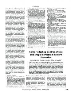
WeB18.4 Measurement zp Ip xp f xic gaps
Plasma boundary
4
3
τ3 7 ms 150 ms 150 ms 150 ms 150 ms
TABLE II P LASMA POSITION AND SHAPE SENSORS PARAMETERS .
2
1
0
III. C ONTROL SYSTEM ARCHITECTURE
−1
First wall
−2
−3 Strike-points
−4 3
4
5
6
7
8
9
Fig. 2. Plasma boundary geometrical descriptors. The figure shows both gaps, which are plasma to wall distances along given directions, and strikepoints.
τ1 15 ms 15 ms 15 ms 15 ms 15 ms 15 ms 15 ms 15 ms 15 ms 15 ms 15 ms 2.5 ms
τ2 15 ms 15 ms 15 ms 15 ms 15 ms 15 ms 15 ms 15 ms 15 ms 15 ms 15 ms 7.5 ms
umax 3.00 kV 1.50 kV 1.50 kV 1.50 kV 1.50 kV 1.50 kV 1.50 kV 1.50 kV 1.50 kV 1.50 kV 1.50 kV 0.15 kV
yr +
-
Converter CS1U&L CS2U CS2L CS3U CS3L PF1 PF2 PF3 PF4 PF5 PF6 VS
The plasma current, position, and shape control system has a twofold task. On one hand it has to vertically stabilize the plasma vertical position; on the other hand it has to drive the plasma current and the geometrical shape descriptors as close as possible to the reference values. It is important to note that these two tasks can be performed on different time scales; indeed while the time constant of the unstable mode in the ITER tokamak is about 100 ms, the settling time in the response to the reference signals can vary between 15-25s. For these reasons it is convenient to use the feedback control structure depicted in Fig. 4. In this scheme the controller Kz aims to stabilize the plasma by applying a voltage signal to the VS converter, while the controller Ky aims to control the output vector y (whose components are the plasma current plus the plasma geometrical descriptors shown in Fig. 2). Note that the vertical stabilization loop is a MISO controller, while Ky is a MIMO controller acting on the stabilized plant.
Ky
Kz
Fig. 4.
The dynamic response of the sensors has been approximated as a first order system characterized by a pole at 1/τ3 . Table II shows the value of τ3 for all the measurements needed for plasma position and shape control. The complete open-loop system to control is depicted in Fig. 3. Plant Model P Power Supplies �
s
W
1 s �
u
1
W
2
Plasma x Ax Bu y c y Cx Du �
�
�
Sensors 1 1 s �
W
P u ic
TABLE I M AIN AND VERTICAL STABILIZATION CONVERTERS PARAMETERS .
e
y
u pf
3
Fig. 3. Open-loop plant to be controlled. yc denotes the vector of the controlled variables.
zp x ic
Control system architecture.
IV. V ERTICAL STABILIZATION In principle, using as actuators the superconductive PF coils, it is possible to perform plasma vertical stabilization by using a simple derivative feedback control of the vertical position z p . Although this approach has been proposed in the past [1], recent investigation pointed out that such an approach implies extremely low closed loop stability margins, in particular for plasma equilibria with internal inductance li exceeding the value of 1.0 (the higher li becomes, the more unstable the plasma). As an example two planned ITER equilibria have been considered [10], showing that the maximum achievable phase margin (with a proportional controller) is about 22 degrees when li = 0.85, while this value drops to 6 degrees, when li increase to 1.1 (see Fig. 5). It worth noticing that in current operating tokamaks, as in
3141
47th IEEE CDC, Cancun, Mexico, Dec. 9-11, 2008
WeB18.4
the JET tokamak, the phase margin ranges from 45 to 60 degrees. Nichols chart − Open−loop system 10 6 dB
5
Gain (dB)
0
proportional action on the current flowing in the in-vessel coils. In the approach here proposed we resort to the latter option, in order to let z p varying according to the request of the plasma shape controller. Let uic be the in-vessel coils voltage vector, then ¡ ¢ uic = kD z˙ p + kI xic = kD cT1z x˙ p f + cT2z x˙ic + cT3z x˙ec + kI xic , where z˙ is obtained straightforwardly from (1b), while kI xic is the proportional action on the in-vessel coils currents, needed to control to zero such currents. The closed-loop state equation is then given by
−5
−10
∗ L11 L e∗ 21 ∗ L31 0 + 0 0
li = 1.1
−15
li = 0.85 180
175
170
165
160
Phase (deg)
Fig. 5. Nichols diagrams of the open-loop system for li = 0.85 (dashed line), and li = 1.1 (solid line).
In order to achieve higher values of phase margin, it is possible to resort to a higher order controller, so as to introduce the needed phase lead in the neighborhood of the crossover frequency. However, in the authors opinion, this solution is not recommendable for the following reasons: • both operational experience on operating tokamaks [6] and simulation studies show that the VS controller parameters must be adaptively changed against the large variations of plasma parameters – geometrical shape and current distribution – occurring during the various phases of the scenario (current ramp-up, limiter/divertor transition, flat-top, heating, ramp-down). The reliability of such a stabilizing adaptive controller strongly depends upon the number of parameters to be adapted, therefore the use of high order controllers should be avoided. • High order controllers, able to significantly improve the phase margin, have the drawback of amplifying the unavoidable noise on the vertical velocity measurement. This amplification could even lead to voltage saturation of the power supplies, and hence could cause the loss of the closed loop stability. For these reasons a vertical stabilization controller with a simple structure would be preferable, in order to envisage effective adaptive algorithms, and to mitigate the effect of the measurement noise on the control performance. A possible to obtain such a simple controller provides for the installation on ITER of in-vessel coils to be used for the vertical stabilization. In particular using in-vessel coils to stabilize the plasma it is possible to eliminate the delay introduced by shielding effect of the vacuum vessel conductors. On the other hand, since the in-vessel coils are close to the plasma, they cannot be superconductive, hence the plasma equilibrium cannot be stabilized only by means of a derivative action on z p . It is then necessary to add either a proportional action on the plasma velocity [11], or a
∗ L12 ∗ e L22 ∗ L32
0 Re22 0
∗ L13 e∗ L 23 ∗ L33 0 0 R33
x˙ p f x˙ic x˙ec xp f I xic = 0 u p f , 0 xec
(2)
where ∗ ∗ e21 L = L21 − kD cT1z , ∗ ∗ e22 = L22 − kD cT2z , L
∗ ∗ e23 L = L23 − kD cT3z , Re22 = R22 − kI .
¡ Letting K = kD kI ), the two gains of the vertical stabilization system can be computed solving the following Bilinear Matrix Inequality (BMI [12]) (A + BKC)T P + P(A + BKC) < −2θ P ,
(3)
where P is a symmetric positive definite matrix, while −1 ∗ ∗ ∗ L11 L12 L13 ∗ ∗ ∗ L22 L23 A = − L21 ∗ ∗ ∗ L31 L32 L33 −1 ∗ ∗ ∗ 0 L11 L12 L13 ∗ ∗ ∗ B = L21 L22 L23 I ∗ ∗ ∗ 0 L31 L32 L33 µ T ¶ T T c1z c2z c3z C= , 0 1 0
0 0 0 R22 0 0
0 0 , R33
,
and θmin < θ < θmax is the desired decay-rate for the vertical stabilization system. The inequality (3) can be effectively solved with PENBMI [13] using a 6-th order reduced model of the plasma. V. P LASMA CURRENT AND SHAPE CONTROLLER As it has been already noted the plasma current and shape control system can act on a slow time scale; as discussed in [1] for the ITER tokamak this time scale is slow also with respect to the decay time of the currents in the metallic structures. Consequently the eddy current dynamics can be neglected in the design of the controller Ky ; this is equivalent to equal to zero both x˙ic and x˙ec in (2), obtaining
3142
∗ −1 x˙ p f = (L11 ) up f ,
y = C1 x p f .
(4a) (4b)
47th IEEE CDC, Cancun, Mexico, Dec. 9-11, 2008
WeB18.4
In particular vector y contains a set of geometrical descriptors which completely characterize the plasma shape, plus the plasma current. In this case we consider as geometrical descriptor 30 gaps plus the two strike-points shown in Fig. 2. On the other hand the number of actuator is equal to nPF = 11. Hence the plant (4) is non-right invertible. For such a plant it is not possible to track a generic set of references with zero steady-state error [14]. For this reason we resort to an approach similar to the one proposed in [7], which has been successfully tested, and now currently adopted on the JET tokamak. Let us consider the ¡ ¢T following partition of the output , where g is the plasma geometrical vector y = gT I p descriptors vector, and I p is the plasma current. If g = C1g x p f , let us consider the following singular value decomposition (SVD) C1g = Ug ΣgVgT , (5) whit Ug ∈ Rng ×nPF , Σg ∈ RnPF ×nPF , Ug ∈ RnPF ×nPF , where ng is the number of plasma boundary geometrical descriptors (gaps and strike-points). The control law is chosen as T −1 T u p f = KSF x p f + KP1 Σ−1 g Ug g + KI1 Σg Ug
+ KP2 I p + KI2
Z t 0
Z t 0
(g − gr )dt
(I p − I pr )dt , (6)
where gr and I pr are the reference on the plasma geometrical descriptors and the plasma current, respectively. It can be shown that (6) tracks the reference of plasma current and minimizes the following steady-state performance index (see [14]): J = lim ||gr − g(t)||2 ,
Now let KSF and KP satisfy ¢ ¡ ∗ −1 (L11 ) KSF + KPC1 = −α I ,
with α > 0. Moreover the output variable y is now given by: ∗ −1 y˙ = −α y +C1 (L11 ) KI η η˙ = y − yr
As far as the integral gain is concerned, it is convenient to choose KI such that ∗ −1 C1 (L11 ) KI = −β I ,
Y (s) =
4
where gre f are constant references to the geometrical descriptors. As a matter of fact, using the ITER linearized models, it turned out that some singular values – depending on the configuration – are one order of magnitude smaller than the others. This fact implies that minimizing the performance index (7) retaining all the singular values result in a high control effort at steady-state, in terms of PF coil currents. In order to achieve a trade-off condition, we control to zero only the error for the n¯ < nPF linear combination related to the largest singular values. Let us consider the matrices ΣM and UMT which corresponds to the n¯ largest singular values of the SVD in (5), and ¡ ¢ T KP = KP1 Σ−1 , M UM KP2 ¡ ¢ −1 T KI = KI1 ΣM UM KI2 ,
2
y = C1 x p f
β
Yr (s) , s2 + α s + β
which is asymptotically stable since α , β > 0. Moreover choosing suitable values to α and β it is possible to assign the desired input/output behavior. Note that (8) and (9) can be accomplished in different ∗ )−1 , and ways, for example letting KP = 0, KSF = −α (L11 † ∗ KI = −β L11C1 . The proposed design approach has been proven to be effective in designing the plasma current and shape controller for ITER. For example Fig.6 to Fig.10 show the performance of the controller in tracking the shape reference shown as solid line in Fig. 6. The controller has been designed with θmin = 8, θmax = 20, α = 0.57, and β = 0.16; note that in this case n¯ = 6.
3
we obtain the following closed loop state equation ¡ ¢ ∗ −1 ∗ −1 x˙ p f = (L11 ) KSF + KPC1 x p f + (L11 ) KI η η˙ = C1 x p f − yr
(9)
with β > 0. In this way the closed loop transfer function which relates yr and y became
(7)
1 Z [m]
t→+∞
(8)
0 −1 −2 −3 −4 2
4
6 R [m]
8
10
12
Fig. 6. Tracking of a given shape. The reference shape is shown as solid line, while the dashdot and the red dash lines show the initial and final (after 25 s) shape, respectively. Note that the plasma-wall distance on the outboard varies from ∼ 6 cm to ∼ 15 cm.
C ONCLUSIONS A solution to the problem of controlling the plasma current, position, and shape in the ITER tokamak has been presented in this work. The proposed approach is based on two separate loops: the first one accomplishes vertical
3143
47th IEEE CDC, Cancun, Mexico, Dec. 9-11, 2008
WeB18.4 In−vessel coil current
Mean square error on plasma shape 1000
0.09
0
0.08
−1000
0.07
xic [A]
Error [m]
−2000
0.06
−3000
0.05 −4000
0.04
−5000
−6000
0.03
0.02 0
5
10
15
20
−7000 0
25
5
10
15
20
25
Time [s]
Time [s]
Fig. 7. Tracking of a given shape. Mean square error on the controller plasma shape descriptors.
Fig. 10. Tracking of a given shape. In-vessel coil current time trace. Note that the maximum required current (∼ 70 kA) is within the limit of ∼ 100kA envisaged for the ITER design review.
Plasma current variation 8000
proposed plasma shape and current controller allows us to track extremely shaped plasmas, minimizing the error between the actual plasma boundary and the desired shape over up to 32 plasma geometrical descriptors. Simulation results have proven the effectiveness of the proposed approach.
6000 4000
Ip [A]
2000 0 −2000
ACKNOWLEDGEMENTS
−4000
This work was partially supported by Italian MiUR (PRIN grant #2006094025).
−6000 −8000
0
5
10
15
20
R EFERENCES
25
Time [s]
Fig. 8. Tracking of a given shape. Time trace of the plasma current variation with respect to its reference value. PF currents variations 7000 6000 5000 4000
xpf [A]
3000 2000 1000 0 −1000 −2000 −3000
0
5
10
15
20
25
Time [s]
Fig. 9. Tracking of a given shape. Time traces of the PF currents variations. These required currents for shape control are within the allowable limits of ∼ 8 kA.
stabilization, while the second one tracks both plasma current and shape. Since the vertical stabilization loop makes use of in-vessel coils, a reduction of the delay due to the shielding effect of the passive structures is attained, permitting to improve the system performance. Thanks to its structure, the proposed solution for the vertical stabilization permits to envisage effective adaptive algorithms. Furthermore the
[1] M. Ariola and A. Pironti, “An application of the singular perturbation decomposition to plasma position and shape control,” European Journal of Control, vol. 9, no. 4, pp. 433–443, 2003. [2] IEEE Control Systems Magazine, vol. 25, no. 5, 2005, special issue. [3] IEEE Control Systems Magazine, vol. 26, no. 2, 2006, special issue. [4] J. Wesson, Tokamas. Oxford University Press, 2004. [5] J. B. Lister, A. Portone, and Y. Gribov, “Plasma control in ITER,” IEEE Control Systems Magazine, vol. 26, no. 2, pp. 79–91, 2006. [6] F. Sartori, G. De Tommasi, and F. Piccolo, “The Joint European Torus,” IEEE Control Systems Magazine, vol. 26, no. 2, pp. 64–78, 2006. [7] M. Ariola and A. Pironti, “The design of the extreme shape controller for the JET tokamak,” IEEE Control Systems Magazine, vol. 25, no. 5, pp. 65–75, 2005. [8] R. Albanese and F. Villone, “The linearized CREATE-L plasma response model for the control of current, position and shape in tokamaks,” Nuclear Fusion, vol. 38, pp. 723–738, 1998. [9] G. Ambrosino and R. Albanese, “A survey on modeling and control of current, position and shape of axisymmetric plasmas,” IEEE Control Systems Magazine, vol. 26, no. 5, pp. 76–91, 2005. [10] CREATE Team, “PLASMA POSITION AND SHAPE CONTROL FOR ITER SCENARIOS - Draft Final Report on EFDA Study Contract 07-1702/1579 (TW6-TPO- PLASMADYN1),” CREATE, Tech. Rep., December 2007. [11] J. B. Lister, E. A Lazarus, and G. H. Neilson, “Control of vertical instability in tokamaks,” Nuclear Fusion, vol. 30, no. 1, pp. 111–141, 1990. [12] J. G. VanAntwerp and R. D. Braatz, “A tutorial on linear and bilinear matrix inequalities,” Journal of Process Control, vol. 10, pp. 363–385, 2000. [13] D. Henrion, J. L¨ofberg, M. Ko˘cvara, and M. Stingl, “Solving polynomial static output feedback problems with PENBMI,” in Proc. of the joint IEEE Conf. on Decision and Control and European Control Conference, Sevilla, Spain, December 2005, pp. 7581–7586. [14] G. Ambrosino, M. Ariola, and A. Pironti, “Optimal steady-state control for linear non-right-invertible systems,” IET Control Theory Applications, vol. 1, no. 3, pp. 604–610, 2007.
3144