Plasma-RX: Autonomous Rescue Robots Kamol Chuengsatiansup1, Krittanai Sajjapongse1, Phartara Kruapraditsiri1, Chanin Chanma2, Nawarat Termthanasombat2, Yuttana Suttasupa2, Sukhum Sattaratnamai2, Ekkaluk Pongkaew2, Pakorn Udsatid2, Borirak Hattha2, Panut Wibulpolprasert2, Prasit Usaphapanus2, Nantinee Tulyanon2 Manop Wongsaisuwan3 , Witaya Wannasuphoprasit1 , Prabhas Chongstitvatana2 Department of Mechanical Engineering Department of Computer Engineering 3 Department of Electrical Engineering Faculty of Engineering, Chulalongkorn University Phayathai Rd., Pathumwan, Bangkok, Thailand, 10330
[email protected] 1
2
Abstract - Plasma-RX is a team of robots for search and rescue mission in an urban environment. The robot configuration contains differential drive tracks with front/rear flippers and serial-link arms equipped with cameras. They contain many sensors: thermopile array, CO2 sensor, microphone, tilt sensor, digital compass and laser range finder. For low level control of robots, a processor Arm7 and a special-purpose controller implemented with FPGA are used. An onboard computer performs high level processing such as navigation and victim identification. The navigation algorithm consisted of SLAM for localize and mapping, SIFT for hazmat tag identification. Plasma-RX system can be operated in tele-operated and autonomous mode. Recently, the team has participated in Rescue robot league at World RoboCup 2008, Suzhou, China, and won the first prize and the best-in-class in mobility award. Index Terms: Rescue robots, autonomous robots, RoboCup.
I. INTRODUCTION Advances in robotics technology bring robots into many facets in our life with a purpose to improve quality of life and to reduce risk and casualty. One of such area is the use of robot in a hazard environment instead of human. An urban search and rescue mission is one of those applications. It is very risky to send a human rescue team into a collapsed area. Deploying a robot or a group of robots into the area to get information about area and victims trapped inside would reduce risk and time for human rescue team that would go in later. A versatile platform that can travel through rough and unstructured area is a big challenge. Getting as much useful information from sensor as possible is another challenge. Mapping the area, locate and identify the victims are examples of data processing in the mission. With a lot of information, an autonomous or semi-autonomous system would help an operator to control the robot and to assess the situation in a much more efficient way.
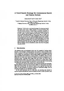
Plasma-RX is a team of rescue robots developed by the Engineering Innovator Club, Faculty of Engineering, Chulalongkorn University, Thailand. This paper describes the design rationales and some important implementation details of Plasma-RX. The experience from participating in the rescue task at RoboCup is also discussed. II. LOCOMOTION Plasma-RX consists of two different configuration robots. RX is a bigger robot and Xiphias is a smaller one. Both have six-track double-flipper drive trains. All robots are equipped with the same sensors and processors (Fig. 1). Thus, all robots have the same method of operations. Three modes of control are available: manual, semi-autonomous and fully autonomous. RX robot weights 45 kilograms, its size is 62 by 65 centimeters, and its height is 40 centimeters when all mechanisms are contracted. Xiphias weights 35 kilograms, and its size is 62 by 65 by 40 centimeters.
Fig. 1 Plasma-RX robot team: Xiphias and RX.
A. Drive train design The goal of designing a robot locomotion system is that the robot can travel through a rough terrain, climb up stair and ramp. A legged-robot is a versatile platform that can travel across uneven terrain quite well, but it requires many actuators, sensors and advanced control algorithm. A wheeldriven robot cannot achieve low radius turning. Thus it is difficult to maneuver in small space unless all wheels steering are used. All wheels steering require many actuators. A trackdriven robot can achieve high traction and zero radius turning, thus, it has been adopted. However, in order to climb obstacles, some additional mechanism is needed. A track-flipper robot, like iRobot PackBot [1], is a proven locomotion system that can climb up stair and obstacle, and is widely used. Front flippers help in climbing and extend the robot spanning length for moving on a discontinuous surface (Fig. 2). They can be kept in an upright position to reduce occupying area when turning. Rear flippers help weight transfer to the front when the robot climbs up to the top of an obstacle and to gain traction on the point of contact with the obstacle.
Fig. 2 The rear flipper helps when climbimg an obstacle.
Fig. 4 The left track module
Fig. 5 The gear train
To gain a high ground clearance, a drive train is placed inside a track to reduce area needed between track and body (Fig. 3). Making tracks modular also gives the benefit that it can be replaced independently from each other (Fig. 4 and 5). One disadvantage is that it is not possible to have a long shaft from left to right track thus make the drive shaft weak. The left and right flipper have do be driven independently.
Drive train
Fig. 3 Comparing the ground clearance between using a drive train between tracks and using a drive train inside the track. Fig. 6 The section view of gear train
B.
Motor selection An overall power requirement is used to determine which motor will be used. An approximately 45 kilograms of the weight of a robot that must climb 45 degrees ramp at the speed of 20 centimeters per second is used to determine the power of the motor. The worst case scenario is that one of the trackdriven motor die, then only one motor has to drive the robot. For flippers, the weight of a robot and the length of flippers are used to determine the power of the motor. The extreme condition is that only one flipper has to generate enough force to lift the whole robot. The choice ends up with 12VDC Maxon RE40 120 watts motors for both track-driven motors and flipper-driven motors. C. Drive train configuration The robot is assumed to travel forward more than backward, so the drive tracks are powered from the rear axle to gain better traction, like the design of a tank. To enable flippers to have a high degree of rotation, the rotation axis of a flipper has to be coincided with the sprocket shaft. There are two possible ways to achieve this, one is to rotate a flipper on the track shaft, and another one is to rotate a track sprocket on the flipper shaft. Since rotational speed of a flipper is lower than the speed of a track, the gear ratio of flipper must be higher than the track. Therefore the flipper gear is larger than the track gear. Thus, it is better to rotate a flipper on the track sprocket axle (Fig. 6). Parameters involved in the drive train design are: the motor gearhead ratio, the gear train ratio and the track diameter. These affect the robot traction and its velocity. The gear train ratio should be minimized, since it will minimize space. Also, keeping the track sprocket diameter small will lower the center of gravity (Fig. 7). A worm gear and a worm wheel are chosen for the gear train, since they have high gear ratio and it is possible to back-drive. This has a benefit that the position can be hold without any power consumption. The calculation gives 19:1 gearhead ratio for tracks and flippers, 10:1 gear train ratio for track sprockets, 40:1 gear train ratio for flippers and 15 centimeters track diameter. With these parameters, the robot can theoretically achieve climbing a 45 degrees ramp at the speed of 30 centimeters per second.
50 centimeters and the distance between the center to center of flippers is 25 centimeters. Tracks are assembled from the attachment chain and pads made of rubber sheet. Using the attachment chain allows flexibility to change the track length, and pads. The rubber sheet has high friction and its compliance structure gives large area of ground contact. This results in high traction. III. ROBOT ARM DESIGN AND SENSORS The purpose of a robot arm is to place the sensor head as close to the target as possible. The size of workspace and the dexterity are major issues to be considered. Using one rotating axis arm with prismatic extension can not cover a workspace below the robot’s own base. Two rotating axis serial-link arm is the easiest way to achieve the goal (Fig. 8). With a base places near the front of the robot, the sensor head will be close to the target. The dimension of 60 and 55 centimeters arm length could achieve the arm that can look across a 1.2 meters height obstacle. The pan and tilt mechanism is installed to enable a sensor head to look around. Also, an additional 2-degree-of freedoms stabilizer, roll and pitch, is used to oriented the sensor head to be always horizontal. This helps a human operator to pan and tilt sensor head.
Fig. 8 A serial-link arm
The robot is equipped with several sensors customized to suite the rescue task in the competition. A laser scanner, Hokuyo URG-04LX, is used for area scanning. The sensor scan 240° semicircle ahead of the robot for measuring the distance between the sensor and obstacles. A three-axis accelerometer and a digital compass, OS5000-US, are used to sense the tilt, roll and heading angle of the robot. Two cameras, Logitech QuickCam Pro 9000, are used. One camera is attached at the end effector of the robot’s arm. Another camera is attached at the back of robot to look at the rear view. A thermopile array, TPA81, is used to detect victim’s temperature. A CO2 sensor and microphones are used to identify victims.
Fig. 7 Comparing the CG of a small and a large track diameter.
IV. CONTROL METHOD D. Track and flipper design The flippers can be placed inside of or outside of the tracks but placing flippers outside the track would achieve a full rotation of flippers. The total spanning length, the track length plus the flipper length, must be larger than 3 stair steps. This allows the robot to travel on a stair smoothly. The flipper length has to be large enough to climb up one stair step. Therefore the distance between the center to center of tracks is
Observing the previous competitions in the rescue robot league, there is a trend towards building robots that are highly intelligent and are autonomous. There are certain advantages for intelligent and autonomous robots in a rescue mission. The main factor for a success in a rescue mission is the ability of a human operator to control robots. It is crucial that the operator should be augmented to facility his/her task. Partly, the robot should travel autonomously and the map should also
be presented to the operator in an intuitive way. These are the goals of Plasma-RX software. Plasma-RX system software consists of several modules. Two robots work as a team. The main robot is under direct control of the operator and the smaller robot works mostly autonomously. In general a robot can be operated in three modes: fully autonomous, semi-autonomous and manual. In fully-autonomous mode, an operator is needed only for starting a mission. The robots will navigate, create an environment map and search for victims automatically. There are many sub-tasks that must be achieved: collecting the sensor data, localizing and map building, victim search and identification, path planning and trajectory generation and finally the control of robot mechanism. A. Localization and Mapping The range data of obstacles are obtained from the laser scanner. The robot orientation is read from three-axis accelerometer and the digital compass. These data are fused; the laser data are corrected according to the robot orientation. The robot location is reported with accuracy within a margin of error. The map is made based on these data. The data represents the robot’s perception of the environment. The EKF SLAM algorithm [2] is used for processing the data to perform autonomous localization and map building. A map is created in GeoTIFF map formats [3] to allow comparison to ground truth of the arena. B. Victim identification and searching The SIFT algorithm [4] is used for victim detection and identification. The image from camera is processed to identify victim tag by extracting features from local images and compare with other tags in the database. In addition to the SIFT algorithm, the temperature data from the thermopile array is used to help the system to make the decision about the existence of a victim in the current searching area. The environmental conditions that are obtained from the victim identification task are sent to the Artificial Intelligence module. The AI module analyzes what the robot should do in each situation, for example, to avoid the obstacle or to decide where to go to find a victim. The AI module is based on eventdriven state machines. C. Path Planning and Trajectory generation The internal representation of the environment is based on grids. The arena is divided into grids. The target location is reached by planning a shortest path from the current location. The trajectory generation creates a cubic spline curve along a specified path. Furthermore, the tilt and roll angles of robots are used to correct the trajectory in order to prevent slip when robot is climbing a ramp. D. Controlling robot mechanism The velocities from the trajectory generation are used to control each motor position and velocity. These commands are passed to the low level controller. The motion control is implements as a PID control on the custom made hardware
based on the field programmable gate array chip (FPGA). The controller has many control channels. This custom-made controller has advantage of speed of operation and compact size. V. HUMAN-ROBOT INTERFACE For Semi-autonomous mode, the user interface is designed to behave like a Real-Time Strategy game interface [5]. Information from localization and mapping is used to generate a top view map of an arena. While the robots travel through the arena, the map is revealed. An operator can set a way-point for the robots by clicking on the map. The robots will travel along the way-point by themselves. In this way, one operator can operate many robots at once. In some difficult situation, the robot can be manually driven. In manual mode, it is quite a difficult task to control several degrees of freedom available in the robot navigation and also the control of the robot arm. In the order to help an operator to manage these complexities, the interface presents an intuitive control. The operator can drive the robots via a keyboard and controls the articulated arm via a mouse by dragging an icon of the sensor head to a desired position. The robot arm control algorithm will calculate the trajectory (assuming a free space) and performs joint-coordinate control to move the end effector to the target position (Fig. 9). The operator can watch the current robot status presented on a graphical user interface. The interface displays several items on the desktop: a top view map, the image from cameras and the graphical information from sensor (Fig. 10). The view of the cameras always stays parallel to the ground using the stabilizing module.
Fig. 9 The control of an articulated arm.
VI. LESSONS LEARNED During the rescue robot league competition at RoboCup 2008 in Suzhou China, Plasma-RX performs the task using the both semi-autonomous and manual mode. The tracks with double flippers on the robot platform can deal with rough terrain very well. The interface for controlling the articulated arm helps an operator to gather victims’ information easily and quickly. There are 18 teams competing in this league. Many teams use fully autonomous robots. In one circumstance, two teams decided to combine their strength in both autonomous and manually driven robots to compete against Plasma-RX team. The result of the competition shows the strength of the design. Plasma-RX won the first prize in the rescue robot league and also received the best-in-class mobility award. Not everything went well in the competition. In early rounds, the fully and semi-autonomous mode did not operate properly. The localization and mapping module worked well but the slip of the track caused the artificial intelligence module to become confused and hence behaved inconsistently. In the final round, the team has to revert to manual mode to control the robot accurately.
ACKNOWLEDGEMENT This project is funded by many parties: Faculty of Engineering, Chulalongkorn University; Alumni of Faculty of Engineering; Siam Cement Group and many sponsors. Also, we would like to thank every faculty members, Thai Robotics Society and the team Independent for their kind supports and advices. The success has come from all these helping hands.
REFERENCES [1]
http://www.irobot.com
[3]
Lina M. Paz; Jose Neira, "Optimal local map size for EKF-based SLAM," Intelligent Robots and Systems, 2006 IEEE/RSJ International Conference on , vol., no., pp.5019-5025, Oct. 2006 http://www.remotesensing.org/geotiff/geotiff.html
[2]
[4] [5]
David G. Lowe, "Distinctive image features from scale-invariant keypoints," International Journal of Computer Vision, 60, 2 (2004), pp. 91-110. Jones, H.; Snyder, M., "Supervisory control of multiple robots based on a real-time strategy game interaction paradigm," Systems, Man, and Cybernetics, 2001 IEEE International Conference on , vol.1, no., pp.383-388 vol.1, 2001
Fig. 10 A graphical user interface for controlling and monitoring robots: (a) GeoTIFF map, (b) An image from camera, (c) Laser data, (d) Top view map, (e) Robot status and the articulated arm control area.