Platform-Based Design and Software Design Methodology for Embedded Systems Alberto Sangiovanni-Vincentelli
Grant Martin
University of California, Berkeley
Cadence Design Systems
Embedded products have become so complex
THE ESSENCE OF embedded-systems design is implementing a specific set of functions while satisfying constraints on characteristics such as performance, cost, emissions, power consumption, and weight. The choice of implementation architecture determines whether designers will implement a function as a hardware component or as software running on a programmable component. In recent years, the functions demanded for embedded systems have grown so numerous and complex that development time is increasingly difficult to predict and control. This complexity, coupled with constantly evolving specifications, has forced designers to consider intrinsically flexible implementations—those they can change rapidly. For this reason, and because hardware-manufacturing cycles are more expensive and time-consuming, software-
based implementation has become more popular. Processors’ increased computational power and correspondingly decreased size and cost let designers move increasingly more functionality to software. However, along with this move comes increasing difficulty in verifying design correctness. This verification is critical due to safety considerations in several application domains— transportation and environment monitoring, for example. In traditional, PC-like software applications, these safety issues typically don’t come up. In addition, the software world has paid little attention to hard constraints on software’s reaction speed, memory footprint, and power consumption—all crucial issues for embedded systems—because they are relatively unimportant in traditional software development. In embedded-systems design, such hard software characteristics are unavoidable. It is no wonder, then, that there is a crisis in embedded-software design. Along with the pressure on system designers to choose flexible implementations, the industry is also witnessing IC manufacturers’ growing preference for chips that will work for several designs. This lets manufacturers amortize development cost over a large number of units, as discussed in the sidebar, “Motivations for platform-based design.” This alignment of designers and manufacturers has resulted in the birth of platform-based design,1,2 in which reuse and programmability are key. We believe that addressing the embedded
November–December 2001
0740-7475/01/$10.00 © 2001 IEEE
and must be developed so quickly that current design methodologies are no longer adequate. The authors’ vision for the future of embeddedsystem design involves two essential components: a rigorous methodology for embedded software development and platform-based design.
23
Roadmaps and Visions
Motivations for platform-based design IC technology lets us integrate so many functions onto a single chip that we can indeed implement an “environment-to-environment” system on a chip. However, we cannot simply view SoCs as an extension of the application-specific IC methodology that has been in vogue for the past 10 years. The economics of SoCs in the ASIC framework are not appealing. The cost of designing and manufacturing SoCs is too high, given the relatively few parts typical in ASIC production. Our platform-based design methodology is an outgrowth of the SoC debate. The overall goal of electronic system design is to balance production costs with development time and cost in view of performance and functionality constraints. Manufacturing cost depends mainly on a product’s hardware components. Minimizing chip size to reduce production cost implies tailoring the hardware to product functionality. The cost of a state-of-the-art fabrication facility continues to rise. A new 300-mm, 0.13- or 0.10-micron, high-volume manufacturing plant today costs about $3.5 billion.1 The ITRS predicts that although manufacturing complex SoC designs will be feasible—at least down to 50-nm minimum feature sizes—producing practical masks and exposure systems will likely be a major bottleneck for such chips’ development. That is, the cost of masks will grow even more rapidly for these fine geometries. A single mask set and probe card for a next-generation chip costs more than $1 million for a complex part—up from less than $100,000 a decade ago.2 This leads us to the first motivation for a move to platform-based design:
Design costs are rising exponentially because of products’ increased complexity (especially in embedded software), the challenges posed by physical effects for deep-submicron design, and the shortage of talent. According to Sematech, design productivity is falling behind exponentially with respect to technology advances. Time-to-market constraints are also intensifying so rapidly that even if costs cease to be an issue, it is still becoming plainly impossible to develop complex parts quickly enough. This leads us to a second reason to embrace platform-based design: Motivation B. Design problems are pushing IC and system companies away from full-custom design methods, toward designs that they can assemble quickly from predesigned and precharacterized components. This places priority on design reuse; correct component assembly; and fast, reliable, efficient compilation from specifications to implementations.
Platform-based design can trade off various aspects of manufacturing costs, nonrecurring expenses, and design productivity. Reuse, flexibility, and efficiency are key to this approach.
References 1. S.P. Dean, “ASICs and Foundries,” Integrated Systems Design, Mar. 2001; http://www.isdmag.com/story/ OEG20010301S0051.
Motivation A. Increasing mask and manufacturing setup costs
2. “NRE Charges for SoC Designs to Hit $1M, Study Says,”
are biasing manufacturers toward parts that have guaranteed
Semiconductor Business News, Oct. 1999; http://www.
high-volume production from a single mask set.
csdmag.com/story/OEG19991006S0043.
software crisis and the manufacturing problem necessitates radical changes in embeddedsystems design. In particular, we propose a rigorous methodology for embedded-software development and platform-based design.
■
■
Vision for embedded-system design Our aim is high: a system design methodology and supporting tools that ■ ■
24
address the supply chain integration problem, the linkage between intellectual property (IP) creators, foundries, semiconductor
houses, systems houses, and applications software developers; consider metrics to govern embedded-systems design, including cost, weight, size, power dissipation, and required performance; work at all abstraction levels, from conception to software and silicon implementation and packaging, with guaranteed correctness and efficient trade-off evaluation; and favor reuse by identifying requirements for real plug-and-play operation. To achieve these goals, our embedded-
IEEE Design & Test of Computers
systems design methodology will leverage three basic principles: ■
■
■
Orthogonality. Based on the principle of separation of concerns, the methodology will clearly separate behavior from implementation, and communication from computation. Theoretical framework. Without a rigorous approach, it isn’t possible to achieve correct, efficient, reliable, and robust designs. Solid theoretical foundations will provide the necessary infrastructure for a new generation of interoperable tools that will work at different abstraction levels. These tools will verify, simulate, and map designs from one abstraction level to the next, help choose implementations that meet constraints, and optimize design criteria. The framework will handle both embedded software and hardware designs, and precise semantics will let the framework and tools analyze the design specifications, identify and correct functional errors, and initiate synthesis processes. Platforms. Incorporating this common reuse technique into our methodology will substantially reduce design time and cost. We have formalized and elaborated the platform concept to yield an approach that combines hardware and software platforms into a system platform.
Leveraging these principles, we can build an environment in which designing complex systems will take only days instead of the many months needed today.
Problems with embedded systems To cope with the tight constraints on performance and cost typical of most embedded systems, programmers write today’s embedded software using low-level programming languages such as C or even assembly language. The tools for creating and debugging embedded software are basically the same as those for standard software: compilers, assemblers, debuggers, and cross-compilers. The difference is in quality: Most tools for embedded software are rather primitive compared to equivalent tools for richer platforms. However, besides these tools, embedded software also needs November–December 2001
hardware support for debugging and performance evaluation, which are far more important for embedded software than for standard software. Another characteristic of embedded software is that, because of performance and memory requirements, it typically uses application-dependent, proprietary operating systems. When embedded software was simple, there was little need for a more sophisticated approach. However, with the increased complexity of embedded-systems applications, this rather primitive approach has become the bottleneck. Most system companies have enhanced their software design methodologies to increase productivity and product quality. Many have rushed to adopt object-oriented approaches and other syntactically driven methods. Such methods certainly have value in cleaning up embedded-software structure and documentation, but they barely scratch the surface in terms of quality assurance and time to market. To address these concerns, the industry has sought to standardize real-time operating systems (RTOSs)—through either de facto standards or standards bodies such as the German automotive industry’s Open Systems and the Corresponding Interfaces for Automotive Electronics (OSEK) committee. RTOSs and traditional integrated development environments dominate the embedded-software market. Embedded-software design automation is still a small segment, but work in this area could lead to large productivity gains. In some applications, the need to capture specifications at high abstraction levels has led to the use of modeling tools such as The Mathworks’ Matlab and Simulink. These tools let designers quickly assemble algorithms and simulate behavior. However, the mathematical models these tools support do not cover the full embedded-system design spectrum. For example, they lack formal dataflow support and do not integrate modeling and finite-state machine (FSM) capture. Understanding the mathematical properties of embedded-system functionality is a key part of our vision; at this level, we can achieve the best results in terms of functional correctness and an error-free refinement of the design into its implementation. Technology boundaries between systems and ICs are blurring. A system that needed a
25
Roadmaps and Visions
printed circuit board yesterday is a single chip today. Thus, IC providers must understand system engineering and essentially become subsystem providers. This means that IC providers cannot sell “bare silicon” to system houses as they used to. Instead, they must provide supporting elements such as software development tools and IP blocks that make the system implementer’s job easier. However, today’s IC makers often depend on third parties to provide such IP blocks and tools. As a result, the embedded-systems designer must cope with different user interfaces, programming styles, and IP documentation styles and contents.
Platform-based design The platform concept has been around for years, but multiple definitions make its interpretation confusing. In general, a platform is an abstraction that covers several possible lowerlevel refinements. Every platform gives a perspective from which to map higher abstraction layers into the platform and one from which to define the class of lower-level abstractions that the platform implies. Architecture platforms PC makers develop their products quickly and efficiently around a standard platform that has gradually emerged: the x86 instruction set architecture, a full set of buses, legacy support for the interrupt controller, and the specification of a set of I/O devices. All PCs satisfy these constraints. So in this domain, a platform isn’t a standardized detailed hardware microarchitecture, but rather an abstraction characterized by a set of constraints on the architecture. Thus, the platform is an abstraction of a family of microarchitectures. Chip makers work with another type of platform: a flexible IC that designers can customize for a particular application by “programming” one or more of the chip’s components. Programming can mean metal customization (gate arrays), electrical modification (fieldprogrammable gate array personalization), or software that runs on a microprocessor or digital signal processor (DSP). For embedded software, the platform is a fixed microarchitecture that minimizes mask-making costs but is flexible enough to work for a set of applications so that produc-
26
tion volume remains high over an extended chip lifetime. Microcontrollers designed for automotive applications, such as the Motorola Black Oak PowerPC, exemplify embedded-software platforms. The problem with this approach is the potential lack of optimization, which can lead to chips that aren’t fast or small enough. A better approach is to develop a family of similar chips that differ in one or more components but are based on the same microprocessor, such as Motorola’s Silver and Green Oak. Such a chip family is also a platform. In our vision, ICs used for embedded systems will be developed as an instance of a particular architecture platform. That is, rather than assembling them from a collection of independently developed blocks of silicon functionality, designers will derive them from a specific family of microarchitectures—possibly oriented toward a particular class of problems. The system developer can then modify the ICs by extending or reducing them. In general, platforms are characterized by programmable components. Thus, each platform instance derived from the architecture platform maintains enough flexibility to support an application space that guarantees the production volumes necessary for economically viable manufacturing. The library that defines the platform can contain reconfigurable components. These can be design-time reconfigurable, such as the Tensilica Xtensa processor, which allows considerable configuration of the instruction set processor for applications; or they can be runtime reconfigurable via reconfigurable logic, as with field-programmable gate arrays (FPGAs). The combination of programmable, designerconfigurable processors and runtime-reconfigurable logic yields the “highly programmable” platforms that are the focus of the Mescal project at the Gigascale Silicon Research Center.3 Platform instances A designer derives an architecture platform instance from the platform by choosing a set of components from the platform library or by setting parameters of the library’s reconfigurable components. Programmable components guarantee a platform instance’s flexibility—that is, its abiliIEEE Design & Test of Computers
ty to support different applications. Software programmability yields a more flexible solution because it is easier to modify; reconfigurable hardware executes much more quickly and expends far less power than the corresponding software. Thus, the trade-off here is between flexibility and performance. Platform design issues Today, choosing an architecture platform is more an art than a science. From an application domain perspective, performance and size are the constraints that usually determine the architecture platform. For a particular application, a processor must meet a minimum speed, and the memory system must meet a minimum size. Because each product has a different set of functions, the constraints identify different architecture platforms; more complex applications yield stronger architectural constraints. For a semiconductor provider, limits on production and design costs add platform constraints and consequently reduce the number of choices. The intersection of the application constraints and the semiconductor constraints defines the architecture platforms available for the final product. This process can result in a platform instance that is overdesigned for a given product. In several applications, however, an overdesigned architecture has been the perfect vehicle to deliver new software products and extend the application. We believe that the embedded-systems community will soon accept some degree of overdesign to improve design costs and time to market. A hardware platform’s design emerges from a trade-off in a complex space that includes ■
■
platform flexibility, which is the application space that the range of platform architectures can support; and the architecture providers’ freedom in designing their hardware platform instances.
Once an architecture platform has been selected, the design process involves exploring the design space defined by that platform’s constraints. These constraints can apply not only to the components themselves but also to their communication mechanism. November–December 2001
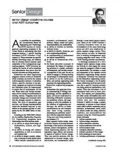
Architecture platform-based design is neither a top-down nor a bottom-up process: it is a meet-in-the-middle approach. The trend is toward semiconductor companies defining platforms and platform instances in close collaboration with system companies. Application developers first choose the architectural components they require, yielding a platform instance. Then they map their application’s functions onto the platform instance; this mapping process includes hardware and software partitioning. For example, the designers might decide to move a function from software running on one of the processors to a hardware block, which could be full-custom logic, an application-specific integrated circuit (ASIC), or reconfigurable logic. Once the partitioning and the platform instance selection are finalized, the designer develops the application software’s final and optimized version. For the best flexibility and time to market, most of the implementation uses software. Recent market analysis indicates that software accounts for more than 80% of system development. Thus, a competitive platform must offer a powerful software development environment. One reason to standardize programmable components in platforms is software reuse. If the instruction set architecture (ISA) remains constant, software porting is easier. This brings us to the definition of an application programming interface (API) platform.1 API platform To maximize software reuse, the architecture platform must be abstracted at a level where the application software can use a highlevel interface to the hardware: the API, also called the programmers’ model. A software layer performs this abstraction, as shown in Figure 1 (next page). This layer wraps the essential parts of the architecture platform: ■ ■ ■
the programmable cores and the memory subsystem through an RTOS, the I/O subsystem through the device drivers, and the network connection through the network communication subsystem.
27
Roadmaps and Visions
Application software
Platform API
Software Hardware-dependent software Hardware
Hardware platform Input devices
I
Output devices
O
Device drivers BIOS
Network communication
RTOS
Network
Figure 1. Layered software structure. The platform API provides the interface between the hardwaredependent software and the middleware and application layers of the software stack. The hardware-dependent software rests on the physical hardware and network. The platform is usually part of a network, and thus provides an interface to the network environment, as illustrated on the right.
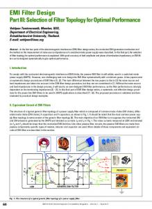
In our conceptual framework, the programming language is the abstraction of the ISA, and the API is the abstraction of a variety of computational resources (the concurrency model provided by the RTOS) and available peripherals (device drivers). The API is a unique abstract representation of the architecture platform through the software layer. With an API so defined, the application software can be reused for every platform instance. Indeed, the API is itself a platform. The RTOS schedules available computing resources and handles communication between them and the memory subsystem. As platform architectures move to multiple cores (already common in second-generation wireless handsets and set-top boxes), the RTOS schedules software tasks across different computation engines. System platform layers Figure 2 captures the basic idea of the sys-
28
tem platform layer.1 The vertex where the two cones meet represents the combination of the API and the architecture platform. You can think of the system platform layer as a single platform obtained by gluing together the upper layer (the API platform) and the lower layer (the collection of components comprising the architecture platform). A system designer maps an application onto the abstract representation, choosing from a family of architectures to optimize cost, efficiency, energy consumption, and flexibility. With appropriate tools, this mapping can take place in part automatically. For this to occur, the tools must be aware of both the architecture features and the API. Thus, the system platform layer combines two platforms and the tools that map one abstraction onto the other. In the design space, there is an obvious tradeoff between the API’s abstraction level and the number and diversity of platform instances covered. A more abstract API yields a richer set of platform instances but also makes it more difficult to choose the optimal platform instance and map automatically to it. Hence, we envision using somewhat different abstractions and tools for several system platform layers. To generalize our thinking, we view design primarily as a process of providing abstraction views. An API platform is a predefined abstraction layer above a more complex device or system that can be used for design at a higher level. A set of operating system calls is also a platform in the sense that it provides a layer of abstraction over an underlying machine. Following this model, a structural design view is abstracted into the API model, providing the basis for the design. To choose the right architecture platform, we need to export to the API level an execution model of the architecture platform that estimates its performance. This model may include size, power consumption, and timing. On the other hand, we can pass constraints from higher abstraction levels to lower levels to continue the refinement process and satisfy the original design constraints. Along with constraints and estimates, we can also use cost functions to compare feasible solutions. In summary, the system platform layer is a comprehensive model that includes the view IEEE Design & Test of Computers
of platforms from both the application and the implementation architecture perspectives, the vertex where the two cones in Figure 2 meet.
Application space Application instance
The embedded-systems methodology roadmap Now let’s turn to the key requirements for the evolution of our broader embedded-system design methodology. We advocate a holistic approach that includes methodology, supporting tools, IP blocks, hardware and software platforms, and supply chain management. Only by taking a high-level view of the problem can we devise solutions that will have a real impact on embedded-systems design. The essential issue to resolve is the link between functionality and programmable platforms. We must start from a high-level abstraction of system functionality that is completely implementation independent and rests on solid theoretical foundations that allow formal analysis. We must also select the platform that can support the functionality while meeting the physical constraints placed on the final implementation. We must implement the functionality onto the platform so that it maintains its properties and meets the physical constraints. Our vision is to have an optimized, semiautomated, transparent, verifiable, and mathematically correct flow from product specification through implementation for software-dominated products implemented with highly programmable platforms. Now let’s discuss the implications of this vision for the major stages of design (specification, refinement and decomposition, and analysis) and implementation (target platform definition, mapping, and links to implementation). Specification Specification means different things to different people. We understand specification to be the entry point of the design process. In our methodology, a specification should contain three basic elements: ■
A denotational description of the system’s functionality that doesn’t imply an implementation. In general, we can express the
November–December 2001
Platform specification
System platform
Platform design-space exploration
Platform instance Architectural space
Figure 2. System platform layer and design flow. The system platform effectively decouples the application development process (the upper triangle) from the architecture implementation process (the lower triangle).
■
denotational description as a set of equations and inequalities in an appropriate algebra. Finding a satisfying set of variables corresponds to executing the specifications. This unambiguous functionality description lets us assess properties and evaluate relationships among the design’s variables. Imperative specifications that fully define the communication mechanism and the elements’ firing rules—FSM specifications, dataflow models, and event-driven models—are refinements to the denotational description. Although imperative specifications are important, the denotational specification is both cleaner and more rigorous. A set of constraints on the system’s final implementation. In general, the constraints can also be expressed as a set of equalities and inequalities, but the variables remain uninterpreted because they involve quantities that have no meaning in the denotational description. A specification of an
29
Roadmaps and Visions
■
automotive engine controller’s behavior, for example, cannot refer to its weight, cost, emissions, or size; these variables are a function of its physical implementation. These kinds of constraints limit the possible implementations of the system’s functionality. A set of design criteria. These are often more qualitative than quantitative characteristics, such as reliability, testability, maintainability, and manufacturability. The difference between constraints and criteria is that constraints, must be met, whereas you do your best to optimize criteria. Multiple criteria often produce multiple conflicts, leading to a complex optimization.
The designer’s goal is to obtain a system implementation whose behavior satisfies the denotational description and the set of constraints, and optimizes the criteria. The language we use to express these elements is an open question, but the most important issue is not the language per se but its semantics. In fact, the issue of the mathematical models and the algebra used to compose and manipulate the models is the essential part of this stage of the design process. Choosing a language is often a compromise among several needs—for example, ease of expression, compactness, and composability. We believe that the specification languages will be heterogeneous. Although application domains most likely have common mathematical underpinnings, they each require different constructs. Today, the mathematical frameworks are partitioned in different domains— that is, FSMs, dataflow graphs, and discreteevent systems. Each of these domains has a particular set of intrinsic properties and execution models that determine the simulation mechanisms used to evaluate the description. Although these formalisms are mathematically rigorous, composing heterogeneous specifications is very difficult. An appropriate mathematical framework will let us establish properties of the composition of heterogeneous models that are impossible today. The embedded-software community has a strong interest in Unified Modeling Language as a standard expression mechanism. Although UML provides some degree of standardization
30
in terms of the syntactical aspects of system design, its semantics are too generic to be useful in our framework. However, rather than define our own syntax for system-level languages, we plan to focus on the language semantics we would need for the required models of computation and their mathematical properties. This work could enrich a language such as UML and contribute to its standardization. We have begun to define an embedded UML profile that would be a basis for objectoriented embedded-software development.4 Refinement and decomposition Once the designer has captured a specification, the design process should progress toward implementation through well-defined stages. The essential idea is to manipulate the description by introducing additional details while both preserving the original functionality and its properties and meeting the constraints that can be evaluated at each new abstraction level. The smaller the steps are, the easier it is to formally prove that constraints are met and properties are satisfied. This process, called successive refinement, is one of the mainstays of our embedded-software methodology. Key issues include the precise definition of what refinement means in the appropriate mathematical framework and the proofs that each refinement maintains the specification’s original properties. During successive refinement, it is often convenient to break parts of the design description into smaller parts so that optimization techniques have a better chance of producing interesting results: This is called decomposition. We must determine whether the decomposed system satisfies the original specifications. Composition is the inverse transformation of decomposition. Thus, successive refinement, decomposition, and composition are the three basic operations we use to move toward implementation. Both composition and decomposition are difficult when the parts that are to be composed or that result from the decomposition use heterogeneous models. The mathematical framework must provide the foundations for showing the relationship between the system before and after these transformations. IEEE Design & Test of Computers
Analysis While marching toward the final implementation, designers sometimes take paths that lead to designs that have no chance of satisfying some of the constraints. Hence, designers must have tools that evaluate intermediate results with respect to the constraints. The essential issue is finding appropriate models at this abstraction level that can carry enough information about the ultimate physical implementation. The alternative is to go far down the implementation path and use detailed models that contain the variables involved in the constraints. A register-transfer-level (RTL) model of a processor, together with simulation, can give very accurate information—but at the cost of long computing time. In addition, it might provide information that is more precise than necessary to assess how a choice meets our constraints. Static analysis methods such as Stars5 and abstract dynamic models can offer up to a thousand times the performance of simulation using detailed models. At a high abstraction level, formal analysis might also be an option. Target platform definition The methodology must use the right notation to define the system platform API: the projection into the embedded-software design space of the platform resources, services, and configurability space. One option is to develop a UML-based description of a target platform that can become the target of refinement and analysis. This description must represent the full range of services (computation, communication, and coordination) that the platform offers in both the software and hardware domains, including configurability options, but it should emphasize the embedded-software perspective. For example, the description could be a multilevel, hierarchical, stack-oriented view of platform services. To carry the design into the platform hardware domain for more detailed analysis of system performance and more detailed hardware and software verification, we can use emerging C++ class-library-based languages such as SystemC 2.0.6 November–December 2001
Mapping The mapping paradigm associates portions of the embedded system’s refined specification with specific implementation vehicles contained within the target platform. Mapping is a fundamental method of configuration and refinement down to implementation. Constraint-driven mapping to a choice of implementation fabrics is essential for hardware and software partitioning and for choosing interfaces between implementation components. Using the system platform API descriptions of a target platform, we can map designs onto the services that this platform offers and conduct various design space exploration analyses for performance (and possibly other domains). Link to implementation Ideally, a platform-based design relies mostly on the selection of reusable service components offered by the platform along with the necessary configuration. However, derivative products often contain new or significantly modified functionality. Thus, our methodology must support software, hardware, and interface synthesis to allow a comprehensive flow from specification to implementation. In addition, we need static configuration (selection of components and connectivity) and dynamic control configuration (for scheduling, resource allocation, and communications) to optimize the implementation. Although designers could satisfactorily select components by hand, the rest of the work should be done automatically to minimize human error and optimize productivity. The value of automatic synthesis has been proven both in software and hardware domains. For software, we can see compilers as synthesis tools: They map from high-level constructs into machine code. For both hardware and software, however, optimization is essential to automatic synthesis. Without it, automatic synthesis would be inferior to manual design. In linking to the implementation, we also need to go from a high-level representation of the system’s functionality to the detailed implementation. Without constraints, this process would be too difficult to carry out automatically. However, because we have already selected an architecture and mapped functionality onto virtual blocks, the automatic approach is conceivable.
31
Roadmaps and Visions
Software synthesis. Almost all system-level
design tools that comprehend software implementations (for example, statecharts, the combination of Simulink and State Flow, ASCET from ETAS, and SPW from Cadence) have some code generation capabilities. The approach is to start from the high-level description that these tools support—for example, graphical state machines, dataflow graphs, and flow diagrams—and generate C code that implements the constructs of the high-level (graphical) languages. We can then use the C code for simulation, or we can output it toward a C compiler for a target implementation. In some cases, the code that these tools generate is acceptable to a system designer. However, frequently a quick analysis lets an experienced designer outperform the automatic code generator. In addition, there has been little work on automatic synthesis of scheduling algorithms to coordinate the functional components to meet constraints. Communication- and component-based7 design include an overall approach to cope not only with the functional blocks but also with their compositions. Some researchers have made progress in the communication area with time-triggered architectures and synchronous languages, but much work remains in terms of optimal selection of a communication mechanism among software components. In the FSM domain, preliminary results stemming from work on the Berkeley Polis system8 and additional research indicate that FSMbased descriptions are more amenable to automatic synthesis. Over the years, researchers have published some code generation work on dataflow graphs, and the results are widely available. Although quality is constantly improving, humans can still outperform automatic tools in many cases. We suspect that the problem lies in taking a global view of the computational structure and understanding the memory organization, which is quite complex for highly optimized DSPs. This area of research is vital to improving the quality of dataflow code generation to automate software synthesis. Hardware synthesis. Researchers have
explored hardware synthesis for many years,
32
and good algorithms are available for generating netlists of gates from an RTL description of the logic. If the modules to be generated use an implementation fabric of gates or low-complexity logic (standard cells or FPGAs), we can apply existing commercial tools. However, if the implementation modules’ hardware architecture is not specified, we must rely on behavioral synthesis, which, despite much research, has not been widely adopted. By leveraging an understanding of platform-based design, we can advance the state of the art in this domain. Another interesting area is mapping onto highly programmable platforms, including generating customized application-optimized processors, as in the HP Labs PICO project.9 Finally, hardware synthesis must also encompass interface synthesis based on optimized generation from various easily configurable communication pattern templates.
OUR VISION for embedded systems unites platform-based design with a unified embeddedsoftware flow from specification through implementation. Realizing this vision will require additional research, tool and methodology development, and experimental applications. Moreover, cooperation is needed between system houses and IC makers. System houses must increase software productivity and quality while facing increasing complexity in both customer product requirements and the hardware they use to improve performance and meet constraints. IC makers must develop platforms that system houses can use promptly and effectively, with as little risk as possible in terms of market share and architecture adequacy. If these two sides of the electronics world do not adopt a cooperative vision, the future of embedded systems will be difficult. If they do, a codesign methodology will be a reality. Our work at the Gigascale Silicon Research Center, UC Berkeley, and Cadence Research Laboratories is tackling many of the details needed to bring about this reality. The Metropolis system, under development with GSRC sponsorship, embodies the approach we have presented.
IEEE Design & Test of Computers
Other design systems also address the main issues we’ve described, although with different emphases and modeling techniques. Examples are the Fresco system developed under the direction of Thomas A. Henzinger, the Mescal system under the direction of Kurt Keutzer and Sharad Malik, and the Ptolemy II system under the direction of Edward A. Lee. Although our work is still conceptual, we believe that practical progress is possible, and that the next few years will see substantive steps toward our goals. ■
6. S. Swan, “An Introduction to System-Level Modeling in SystemC 2.0,” Cadence Design Systems, San Jose, Calif., 2001; http://www.systemc.org/ papers/SystemC_WP20.pdf. 7. M. Sgroi, L. Lavagno, and A. Sangiovanni-Vincentelli, “Formal Models for Embedded System Design,” IEEE Design & Test of Computers, vol. 17, no. 2, Apr.-June 2000, pp. 14-27. 8. F. Balarin et al., Hardware-Software Co-Design of Embedded Systems: The POLIS Approach, Kluwer Academic, Norwell, Mass., 1997. 9. S. Aditya, B. Ramakrishna Rau, and V. Kathail, “Automatic Architectural Synthesis of VLIW and
Acknowledgments
EPIC Processors,” Proc. Int’l Symp. System Syn-
The two areas of investigation presented here constitute the main research lines of the SystemLevel Design effort at the Gigascale Silicon Research Center—a large, multisite research project under the direction of Richard Newton.3 Cadence Research Laboratories and the SystemLevel Design Group have also heavily invested in these areas. We acknowledge, with thanks, the ideas and suggestions we received for this vision from Alberto Ferrari, Felice Balarin, Jerry Burch, Tom Henzinger, Ed Lee, Luciano Lavagno, Lane Lewis, Richard Newton, Roberto Passerone, Ellen Sentovich, Frank Schirrmeister, Marco Sgroi, Ted Vucurevich, and Yoshi Watanabe.
thesis (ISSS 99), IEEE CS Press, Los Alamitos,
References 1. A. Sangiovanni-Vincentelli and A. Ferrari, “System Design—Traditional Concepts and New Paradigms,” Proc. Int’l Conf. Computer Design, IEEE CS Press, Los Alamitos, Calif., 1999, pp. 2-12.
Calif., 1999, pp. 107-113.
Alberto SangiovanniVincentelli holds the Edgar L. and Harold H. Buttner Chair of Electrical Engineering and Computer Sciences at the University of California, Berkeley, where he is also vice chair for Industrial Relations. He cofounded Cadence and Synopsys and founded Cadence Research Labs. His research interests include design tools and methodologies, large-scale systems, embedded controllers, and hybrid systems. Sangiovanni-Vincentelli has a doctoral degree in electrical engineering and computer science from Politecnico di Milano, Italy. He is a fellow of the IEEE and a member of the National Academy of Engineering.
2. H. Chang et al., Surviving the SOC Revolution: A Guide to Platform-Based Design, Kluwer Academic, Norwell, Mass., 1999. 3. K. Keutzer et al., “System Level Design: Orthogonalization of Concerns and Platform-Based Design,” IEEE Trans. CAD of Integrated Circuits and Systems, vol. 19, no. 12, Dec. 2000, pp. 1523-1543. 4. G. Martin, L. Lavagno, and J. Louis-Guerin, “Embedded UML: A Merger of Real-Time UML and Co-Design,” Proc. Int’l Workshop Hardware/Software Co-Design (Codes 01), IEEE
Grant Martin is a fellow in the labs of Cadence Design Systems. His research interests include system-level design, systems on chips, platform-based design, and embedded software. Martin has a BMath and an MMath in combinatorics and optimization from the University of Waterloo, Canada.
CS Press, Los Alamitos, Calif., 2001, pp. 23-28. 5. F. Balarin, “Worst-Case Analysis of Discrete Systems,” Proc. Int’l Conf. Computer-Aided Design (ICCAD 99), ACM Press, New York, 1999, pp. 347-352.
November–December 2001
Direct questions and comments about this article to Grant Martin, Cadence Design Systems, 555 River Oaks Parkway, San Jose, CA 95134;
[email protected].
33