FPGA in embedded systems is gaining importance due to its increasing
capabilities ... necessary [4]. Smart camera is an important embedded system
dedicated.
International Journal of Modeling and Optimization, Vol. 2, No. 4, August 2012
Platform-Based Extensible Hardware-Software Video Streaming Module for a Smart Camera System Jai Gopal Pandey, Member, IACIST, Shashwat Purushottam, Abhijit Karmakar, and Chandra Shekhar
heterogeneous resources on one single chip [3]. The number of resources in FPGA is very high so that one FPGA can practically handle many processing operations. Data coming from the sensor or any acquisition device is directly processed by the FPGA; no other external resources are necessary [4]. Smart camera is an important embedded system dedicated to application-specific image acquisition and their processing catering to various application needs [5]–[7]. Image and video processing in smart cameras are required to manage and process a large amount of data within real-time constraints. The image acquisition block plays a vital role of capturing the incoming video, and thus, determines the smart camera system’s overall performance. Also, several complex image-processing applications require image acquisition modules to meet the variable performance need [8], [9]. Digital image acquisition and processing in medicine, focusing on x-ray projection imaging has been presented in [9]. An image acquisition module build around CMOS image sensor have been developed in [10]. A FPGA board has been used in [6] to capture still frames from an analog video camera. In this approach a frame grabber card which is a daughter card to the FPGA board has been interfaced through an I/O port of the board. To capture and exchange video data with the hardware co-processor, LabVIEW host application controlling a frame grabber has been used in [11]. In the context of smart camera platform, Xilinx Virtex-4 FX (XC4VFX12) FPGA based platform has been used in [12], which contains embedded PowerPC405 microprocessor. In their work they have presented an architecture for image acquisition and processing using a CMOS sensor, which has been interfaced with FPGA platform for the smart camera. They have reported that the available FPGA slices (5,472 slices) is not sufficient for incorporating any complex image or video processing algorithm, as their designed system occupied almost all of the available slices. Further they have mentioned that in order to implement complex image processing algorithms it would be necessary to choose a FPGA device with higher amount of resources. It is evident that, for a reasonably complex image processing algorithm, much larger FPGA device would be necessary. In line of [12], we have selected Xilinx ML-507 platform which has Virtex-5 FX FPGA device (XC5VFX70T) for implementing the video acquisition system so that larger and more complex algorithms can be implemented for a platform-based smart camera system. The main aim of the presented work is to build extensible hardware-software video streaming module around Virtex-5 FPGA fabrics with FPGA-embedded PowerPC 440 processor for real-time video processing applications in smart
Abstract—Driven by the rapid technological advances and ever-increasing market demand for new applications, system complexities have grown at almost an exponential rate. The traditional design methods of providing complete hardware or software solutions to meet system specifications are fast becoming infeasible. The modern-day complex systems, thus, invariably, include both software and heterogeneous hardware components. With the advent of today's highly integrated Field Programmable Gate Array (FPGA) it is possible to have a software programmable processor and hardware computing resources on the same chip. Apart from having sufficient logic blocks on which the hardware is implemented these chips also have an embedded processor with system software to implement the application software around it. In this paper, using a platform-based design approach a video acquisition module is designed that is the basic step towards developing a smart camera system. Video streaming is central to the video acquisition system and forms the vital part on which other video processing applications are developed. The Virtex-5 based Xilinx ML-507 platform is used for developing the proposed extensible hardware-software video streaming module. The Xilinx Embedded Development Kit (EDK) design tool is used for the required hardware and software to work in an integrated fashion. The utility of this module is demonstrated in a smart camera system. Index Terms—Platform-based design, embedded system design, FPGA-based design, hardware-software co-design, system level design, video acquisition.
I. INTRODUCTION A general purpose image and video processing system typically consists of an image acquisition system, a personal computer that provides the processing power and image processing software [1]. Modern image and video processing algorithms are computing resource intensive. Traditional PC or DSP-based systems are for the majority of the time unsuitable under real-time constraints. They cannot achieve the required high performance that is expected when working with video frame rates. Therefore, dedicated embedded architectures need to be designed. FPGA-based implementation has become increasingly attractive for modern embedded systems. An overview of computer vision algorithms on FPGAs has been presented in [2]. The role of FPGA in embedded systems is gaining importance due to its increasing capabilities and availability of powerful Electronic Design Automation (EDA) tools. Today’s FPGAs integrate Manuscript received May 10, 2012; revised June 29, 2012. J. G. Pandey, A. Karmakar, and C. Shekhar are with Council of Scientific and Industrial Research - Central Electronics Engineering Research Institute (CSIR-CEERI), Pilani-333031, India (email:
[email protected];
[email protected];
[email protected]). S. Purushottam is with Computer Science Department, University of California, Los Angeles, USA- 90095 (email:
[email protected]).
482
International Journal of Modeling and Optimization, Vol. 2, No. 4, August 2012
camera system. The module, as designed in this paper is easily configurable for various video resolutions. Without any modification to the hardware, it can be extended and used in various image and video processing applications. The rest of the paper is organized as follows: Section II describes the smart camera system. Platform-based system design methodology is presented in Section III. Section IV describes about the video processing platform for video streaming application. The design of modules for the image acquisition system using FPGA-based video processing platform is presented in Section V. This section also discuss about the extensible hardware-software video streaming module for the smart camera system. Experimental results are described in Section VI. Section VII concludes this paper.
II.
required for the reuse of hardware and software components. Platform-based design offers reuse of architecture and also provides the requisite programmability [13]. Architecture platform is a family of micro-architectures. Every component of the family can be obtained rapidly through the personalization of an appropriate set of parameters controlling the micro-architecture [14]. The flexibility and the capability of supporting different applications (in the fixed design domain) come from the presence of programmable components. Software programmability comes from the availability of microprocessor, where as the hardware programmability comes from the presence of reconfigurable blocks of FPGA [15]. Every element of the platform can be selected and used through the customization of an appropriate set of design parameters which control its micro-architecture. The user may not be concerned about the design details of each and every component of the platform.
SMART CAMERA SYSTEM
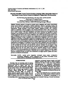
A smart camera captures still or moving pictures, converts into digital; processes and interprets the data that it captures in real-time and takes decision intelligently. It captures high-level description of a scene and performs real-time analysis of what it sees [5]–[7]. Thus, a smart camera is a camera that has the ability not only to take pictures but also, more importantly, to make intelligent decisions of what is happening in the image and in some cases take appropriate actions on behalf of the camera user. The block diagram of the smart camera system is shown in Fig. 1.
ROI
Video Camera
Video Acquisition
Data Processing
IV. VIDEO PROCESSING PLATFORM In this section, we describe the details of the Xilinx Virtex-5 FPGA based video processing platform on which the video acquisition system is developed. A. Xilinx ML-507 FPGA Evaluation Platform The Xilinx ML-507 evaluation platform contains a Virtex-5 FPGA device (XC5VFX70T) and various on-board peripherals. The board contains a VGA input video codec connector that supports connectivity to an external VGA source. The VGA input codec circuitry utilizes an Analog Devices AD9980 video decoder (DEC) device. The AD9980 is an 8-bit 95 MSPS interface optimized for capturing YPbPr video and RGB graphics signals. AD9980’s encode rate of 95 MSPS supports HDTV video modes and graphics resolutions up to XGA (1024×768 at 85 Hz). The DVI connector present on the board supports an external DVI/VGA monitor. The DVI circuitry utilizes a Chrontel CH7301C Display Controller. This Display Controller is capable of a maximum of 16001200 resolution with 24-bit color and it is configurable by the Video IIC (Inter-IC).
Display
Fig. 1. Block diagram of smart camera system.
The smart camera system consists of a data acquisition block and application-specific data processing block. It possesses an analog video camera for capturing the real-time video within its region-of-interest (ROI) and a monitor to display the processed results. It may contain a wide range of algorithms to extract meaning from the streaming video. This device can support a wide variety of applications including remote surveillance, motion analysis, traffic monitoring, etc [7]. The architecture of smart camera systems has been presented in [5], [6] based on which an application developer can construct a parallel image processing application with minimal effort. The next section illustrates the platform-based design approach in details.
B. PTZ Camera The camera chosen for the development of the video acquisition system is Sony EVI-D70P Pan-Tilt-Zoom (PTZ) camera [16]. The PTZ camera can adjust its orientation with respect to the ROI which is a very important functionality for any smart camera system. The orientation of the camera can easily be controlled through RS-232 port on the ML-507 board. The camera can be interfaced with VGA IN port of the ML-507 platform. The camera works with PAL signal system with composite video and S-video as the analog video outputs are available with effective pixels of 752 (H) 582 (V). The output of the camera is connected to the video IN port of the PAL to VGA converter which is described below. C. PAL to VGA Converter The PAL standard is incompatible with this FPGA board (or even with computer video standards), which uses RGB video signals. To convert composite video into VGA form, a PAL to VGA converter is used. It converts the composite
III. PLATFORM-BASED DESIGN A platform is a coordinated family of hardware and software architectures that satisfy a set of architectural constraints (power, performance, area, design time, and cost) 483
International Journal of Modeling and Optimization, Vol. 2, No. 4, August 2012
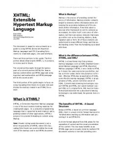
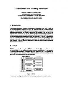
interface, util-vector logic along with some of the Xilinx Spartan-3A DSP video starter kit [17] IPs are used, along with the PowerPC 440 embedded processor. The hardware blocks as used in the implemented system are shown in Fig. 3 and described in the following subsections.
analog video/S-video into the corresponding RGB analog form. Section V discusses our design approach using the Xilinx ML-507 platform.
A. DVI_IN The dvi_in peripheral core provides a connection to the AD9980 video decoder chip. This peripheral core brings in the input signals from the input chip, registers the signals, and groups the video signals into a unified bus that can be connected to other IPs for processing. Along similar lines a bus interface called DVI_VIDEO_OUT is defined for the dvi_in peripheral core outputs.
V. THE DESIGN APPROACH In this design PowerPC 440 embedded processor is used for the interfacing of FPGA-based custom modules and IPs along with the configuration of platform peripherals. Fig. 2 shows the block diagram of our design approach with Xilinx Embedded Development Kit (EDK). The software environment of the system consists of application software and device drivers. The hardware part of the system includes the configurable logic blocks in FPGA. This integration of software and hardware provides the complete system functionality. The smart camera system requires interfacing of PTZ analog camera with the FPGA board. For this interfacing VGA IN port is used. The video decoder chip registers are configured using the IIC bus according to the resolution and frame rate of the incoming video. This is achieved by using the IIC bus controller's low-level device driver functions. To interface a VGA monitor, DVI OUT port is used after configuring video display controller chip registers through the IIC bus. Next, a design is implemented in the FPGA logic which facilitates the streaming of video from camera to the monitor through the FPGA logic in real-time. For the implementation of the design, the Xilinx provided IPs, namely, Digital Clock Manager (DCM), Processor Local Bus (PLB), XPS IIC
B. DE_GEN The de_gen peripheral core provides the ability to generate a Data Enable (de) signal for analog video streams. The data enable signal marks the beginning of the active video that needs to be written to the external memory. The core achieves this by analyzing the input hsync and vsync signals combined with the front porch and back porch clock cycles based on the VGA protocol. The PowerPC processor writes the porch values to the block over the PLB interface based on the resolution. The vertical back porch value includes all of the clock cycles between the active edge of hsync and the first active video pixel. This includes the vertical back porch, the hsync pulse width, and the border preceding the first active video pixel.
plb_v46_0
Fig. 2. Block diagram of the design in Xilinx EDK.
484
International Journal of Modeling and Optimization, Vol. 2, No. 4, August 2012
de
hsync
R [7:0]
VDEC
DVI_IN
DE_Video_IN [26:0]
DVI_Video_OUT [25:0]
vsync
vsync hsync Data [11:0]
DE_GEN
DVI_OUT
DISPLAY CONTROLLER
DVI_CLK_n
G [7:0] DVI_CLK_p
Reset_n
B [7:0]
CLK
Video_IN_CLK
FPGA Fig. 3. Hardware blocks in the implemented system.
The vertical front porch value includes all of the clock cycles between the last active video pixel and the active edge of hsync. This includes the vertical front porch and the border following the last active video pixel. The horizontal back porch value includes all of the lines of data between the active edge of vsync and the first line of active video. This includes the horizontal back porch, the vsync pulse width, and the border preceding the first line of active video. The horizontal front porch value includes all of the lines of data between the last line of active video and the active edge of vsync which indicates start of a new frame. This includes the horizontal front porch as well as the border following the last line of active video. Bus interfaces called DVI_VIDEO_IN and DVI_VIDEO_OUT are defined for the de_gen peripheral core.
is shown in Fig. 5. In this timing diagram the vsync signal shows the control of the VGA monitor to start displaying a new image or a new frame of a video. The hsync signal controls the monitor to refresh another row of 640 pixels. The video signal redraws the entire screen 60 times per second.
C. DVI_OUT The dvi_out peripheral core provides a connection to the CH7301C DVI Transmitter Device. This peripheral core brings in the DVI_VIDEO_IN bus that connects to the DVI_VIDEO_OUT interface of the de_gen core and formats the video data to the format required by the display controller device. The CH7301 is capable of driving either digital DVI displays or analog VGA displays. For analog displays, the de signal is required. The ML507 board has a DVI port as the output port, so the digital video interface signals are generated by the dvi_out core. A DVI-to-VGA converter is used externally in case of analog displays.
Fig. 4. Captured video from the camera.
Table I shows the post-synthesis clock frequencies of the design. TABLE I: POST-SYNTHESIS CLOCK FREQUENCIES OF THE DESIGN Module
VI. RESULTS The real-time video is captured from the PTZ camera. The captured video is converted into a set of frames by using customized logic in FPGA fabric. The stored frames are converted back into VGA format by using customized FPGA logic, which are displayed on a VGA monitor using Xilinx ML-507 platform. The output video data is displayed on the VGA monitor as shown in Fig. 4. The timing details of the design as obtained from Xilinx ChipScope Pro analyzer for 640x480@60Hz video resolution 485
CLK Port
Max freq
xps_iic_0
SPLB_Clk
234.522MHz
de_gen_0
SPLB_Clk
234.632MHz
de_gen_0
clk
234.632MHz
xps_iic_1
SPLB_Clk
235.682MHz
xps_bram_if_cntlr_1
BRAM_Clk
281.793MHz
RS232_Uart_1
SPLB_Clk
310.849MHz
plb_v46_0
PLB_Clk
398.724MHz
proc_sys_reset_0
Slowest_sync_clk
406.009MHz
dvi_in_0
clk
529.381MHz
dcm_module_0
CLKIN
1239.157MHz
International Journal of Modeling and Optimization, Vol. 2, No. 4, August 2012
Fig. 5. Timing details of the design as obtained from Xilinx ChipScope Pro analyzer. W. MacLean, “An Evaluation of the Suitability of FPGAs for Embedded Vision Systems,” in Proc. of 2005 IEEE Computer Society Conference Computer Vision and Pattern Recognition, June 2005, pp. 131–131; doi 10.1109/CVPR.2005.408 . [3] Xilinx FPGA. [Online]. Available: http://www.xilinx.com/products/devices.htm [4] Xilinx ML-507 FPGA platfrom. [Online]. Available: http://www.xilinx.com/ml507 [5] H. Broers, W. Caarls, P. Jonker, and R. Kleihorst, “Architecture Study for Smart Cameras,” in Proc. of EOS Conference on Industrial Imaging and Machine Vision, European Optical Society, Munich, Germany, June 2005, pp 39-49. [6] M. Leeser, S. Miller, and H. Yu, “Smart Camera based on Reconfigurable Hardware Enables Diverse Real-time Applications,” in Proc. of the 12th annual IEEE Symposium on Field-programmable Custom Computing Machines (FCCM’04), 2004, pp 147-155. [7] W. Wolf, B.Ozer, and T. Lv, “Smart Cameras as Embedded Systems,” IEEE Computer Society, vol. 35, issue 9, September 2002, pp. 48-53. [8] B. Jahne, Practical handbook on image processing for scientific and Technical applications, 2nd ed., CRC Press, 2004. [9] T. Aach, U. Schiebel, and G. Spekowius, “Digital Image Acquisition and Processing in Medical X-Ray Imaging,” Journal of Electronic Imaging, Publisher SPIE, vol. 8, 1999, pp 7-22. [10] V. Fresse, A. Aubert, and N. Bochard , “A Predictive NoC Architecture for Vision Systems Dedicated to Image Analysis,” EURASIP Journal on Embedded Systems, vol. 2007, issue 1 Article ID 97929, doi:10.1155/2007/97929, January 2007. [11] J. A. Kalomiros and J. Lygouras, “Design and Evaluation of a Hardware/Software FPGA-Based System for Fast Image Processing,” Microprocessors and Microsystems, vol. 32, issue 2, March 2008, pp 95-106. [12] I. Bravo, J. Balinas, A. Gardel, J. L. Lazaro, F. Espinosa, and J. Garcia, “Efficient smart CMOS camera based on FPGAs oriented to embedded [2]
VII. CONCLUSION We have demonstrated a platform-based design approach for an image/video acquisition application which is the precursor to any image or video processing application. In the developed extensible hardware-software video streaming module, we stream the frames on an individual basis through the FPGA fabric using custom designed hardware IPs in realtime. It enables the camera to be used in a variety of real-time applications that will help in realizing the goal of developing the smart camera. ACKNOWLEDGMENT The authors would like to thank Dr. A. S. Mandal, Senior Principle Scientist, IC Design Group, CEERI, Pilani, for his valuable advice and kind support. The authors also wish to thank Sh. Raj Singh, Chief Scientist, IC Design Group, CEERI, Pilani, for providing the necessary resources through the MCIT/DIT sponsored project “Special Manpower Development for VLSI Design and Related Software (SMDP).” REFERENCES [1]
B. Jahne, Digital image processing, 6th revised and extended edition, Springer Pub., 2005.
486
International Journal of Modeling and Optimization, Vol. 2, No. 4, August 2012
[13]
[14] [15]
[16] [17]
specialization in computer architecture. Before this, he completed his bachelor's degree (B.E. Hons.) in Electronics & Instrumentation from the Birla Institute of Technology & Science (BITS), Pilani, India in 2009. His research interest includes computer vision and vision-based applications using FPGA and domain-specific computing for embedded systems. Mr. Purushottam is a member of the ACEEE.
image processing,” Sensors, 11(3), 2282-2303. doi: 10.3390/s110302282, 2011. L. Carloni, F. De Bernardinis, C. Pinello, A. L. Sangiovanni-Vincentelli, and M. Sgroi, "Platform-Based Design for Embedded Systems," in The Embedded Systems Handbook, R. Zurawski, Ed., Boca Raton, FL: CRC Press, 2005, pp. 1-26. F. Vahid and T. Givargis, “Platform Tuning for Embedded Systems Design,” Computer, vol. 34, issue 2, February 2001, pp. 112-114. A. S. Vincentelli and G. Martin, “Platform Based Design and Software Design Methodology for Embedded Systems,” Design and Test of computers, IEEE, vol. 18, no. 6, November-December 2001, pp. 23-33. Sony EVI-D70 PTZ camera. [Online]. Available: http://www.goelectronic.com/store/sony_evi-d70.html Virtex-4 video starter kit. [Online]. Available: http://www.xilinx.com/products/devkits/HW-V4SX35-VIDEO-SK-U S.htm
A. Karmakar was born in West Bengal, India, in 1971. He received the B.E. degree in electronics and telecommunication engineering in 1993 from Jadavpur University, India, the M.Tech. degree in electrical engineering from the Indian Institute of Technology (IIT), Madras, India, in 1995, and the Ph.D. degree in electrical engineering from IIT Delhi in 2007. He is with Council of Scientific and Industrial Research- Central Electronics Engineering Research Institute (CSIR-CEERI), Pilani, Rajasthan-333031, India since 2005. He is working as a Scientist with the IC Design Group, CEERI, Pilani, since 1995. His research interests are in the areas of VLSI design, digital signal processing, auditory modeling, and speech quality evaluation. Dr. Karmakar is a member of IEEE and IETE and life member of Semiconductor Society of India.
J. G. Pandey was born in the city of Gorakhpur, India in 1979. He received Master of Science (Electronics) degree from D. D. U. Gorakhpur University, India in 2001 and Master of Technology degree in Electronics Design and Technology, with specialization in VLSI Design from U. P. Technical University, Lucknow, India, in 2003. He is with Council of Scientific and Industrial Research- Central Electronics Engineering Research Institute (CSIR-CEERI), Pilani, Rajasthan-333031, India since 2005. He is working as a Scientist with IC Design Group, CSIR-CEERI, Pilani, in the area of real-time image/video processing with FPGA platform. His research interest includes VLSI design and high-performance computer architecture for embedded system applications. Mr. Pandey is a member of IEEE, IACSIT, and life member of Semiconductor Society of India.
C. Shekhar was born in India, in 1951. He received M.Sc. degree in Physics in 1971 and Ph.D. degree in 1975, from BITS, Pilani, India. He is with Council of Scientific and Industrial Research- Central Electronics Engineering Research Institute (CSIR-CEERI), Pilani, Rajasthan-333031, India since 1977. He is serving as the Director of CSIR-CEERI, Pilani, since 2003. His research interests include analog and mixed signal design, VLSI design and design methodologies, application specific processors design, CAD for VLSI and Physics and modeling of MOS Devices. He has published several research papers in various reputed international/national journals and conferences. Dr. Shekhar is a Fellow of IETE and Life Member of Indian Physics Association, Semiconductor Society of India and Indo-French Technical Association.
S. Purushottam is currently at the University of California, Los Angeles (UCLA). He was born in the city of Tiruchirapalli in 1987. He is currently pursuing his Masters (MS) in Computer Science at UCLA with a
487


![Extensible Effects - Indiana CS [PDF]](https://m.moam.info/img/260x300/extensible-effects-indiana-cs-pdf_647a3fbe098a9e23528b4568.jpg)